EP1475264A2 - Recreational vehicle locking differential - Google Patents
Recreational vehicle locking differential Download PDFInfo
- Publication number
- EP1475264A2 EP1475264A2 EP04445055A EP04445055A EP1475264A2 EP 1475264 A2 EP1475264 A2 EP 1475264A2 EP 04445055 A EP04445055 A EP 04445055A EP 04445055 A EP04445055 A EP 04445055A EP 1475264 A2 EP1475264 A2 EP 1475264A2
- Authority
- EP
- European Patent Office
- Prior art keywords
- assembly
- differential
- coupler
- transmission
- locking
- Prior art date
- Legal status (The legal status is an assumption and is not a legal conclusion. Google has not performed a legal analysis and makes no representation as to the accuracy of the status listed.)
- Granted
Links
Images

Classifications
-
- B—PERFORMING OPERATIONS; TRANSPORTING
- B60—VEHICLES IN GENERAL
- B60K—ARRANGEMENT OR MOUNTING OF PROPULSION UNITS OR OF TRANSMISSIONS IN VEHICLES; ARRANGEMENT OR MOUNTING OF PLURAL DIVERSE PRIME-MOVERS IN VEHICLES; AUXILIARY DRIVES FOR VEHICLES; INSTRUMENTATION OR DASHBOARDS FOR VEHICLES; ARRANGEMENTS IN CONNECTION WITH COOLING, AIR INTAKE, GAS EXHAUST OR FUEL SUPPLY OF PROPULSION UNITS IN VEHICLES
- B60K17/00—Arrangement or mounting of transmissions in vehicles
- B60K17/04—Arrangement or mounting of transmissions in vehicles characterised by arrangement, location or kind of gearing
- B60K17/16—Arrangement or mounting of transmissions in vehicles characterised by arrangement, location or kind of gearing of differential gearing
-
- B—PERFORMING OPERATIONS; TRANSPORTING
- B60—VEHICLES IN GENERAL
- B60K—ARRANGEMENT OR MOUNTING OF PROPULSION UNITS OR OF TRANSMISSIONS IN VEHICLES; ARRANGEMENT OR MOUNTING OF PLURAL DIVERSE PRIME-MOVERS IN VEHICLES; AUXILIARY DRIVES FOR VEHICLES; INSTRUMENTATION OR DASHBOARDS FOR VEHICLES; ARRANGEMENTS IN CONNECTION WITH COOLING, AIR INTAKE, GAS EXHAUST OR FUEL SUPPLY OF PROPULSION UNITS IN VEHICLES
- B60K17/00—Arrangement or mounting of transmissions in vehicles
- B60K17/34—Arrangement or mounting of transmissions in vehicles for driving both front and rear wheels, e.g. four wheel drive vehicles
- B60K17/344—Arrangement or mounting of transmissions in vehicles for driving both front and rear wheels, e.g. four wheel drive vehicles having a transfer gear
- B60K17/346—Arrangement or mounting of transmissions in vehicles for driving both front and rear wheels, e.g. four wheel drive vehicles having a transfer gear the transfer gear being a differential gear
-
- F—MECHANICAL ENGINEERING; LIGHTING; HEATING; WEAPONS; BLASTING
- F16—ENGINEERING ELEMENTS AND UNITS; GENERAL MEASURES FOR PRODUCING AND MAINTAINING EFFECTIVE FUNCTIONING OF MACHINES OR INSTALLATIONS; THERMAL INSULATION IN GENERAL
- F16H—GEARING
- F16H48/00—Differential gearings
- F16H48/06—Differential gearings with gears having orbital motion
- F16H48/08—Differential gearings with gears having orbital motion comprising bevel gears
-
- F—MECHANICAL ENGINEERING; LIGHTING; HEATING; WEAPONS; BLASTING
- F16—ENGINEERING ELEMENTS AND UNITS; GENERAL MEASURES FOR PRODUCING AND MAINTAINING EFFECTIVE FUNCTIONING OF MACHINES OR INSTALLATIONS; THERMAL INSULATION IN GENERAL
- F16H—GEARING
- F16H48/00—Differential gearings
- F16H48/20—Arrangements for suppressing or influencing the differential action, e.g. locking devices
- F16H48/24—Arrangements for suppressing or influencing the differential action, e.g. locking devices using positive clutches or brakes
-
- F—MECHANICAL ENGINEERING; LIGHTING; HEATING; WEAPONS; BLASTING
- F16—ENGINEERING ELEMENTS AND UNITS; GENERAL MEASURES FOR PRODUCING AND MAINTAINING EFFECTIVE FUNCTIONING OF MACHINES OR INSTALLATIONS; THERMAL INSULATION IN GENERAL
- F16H—GEARING
- F16H48/00—Differential gearings
- F16H48/20—Arrangements for suppressing or influencing the differential action, e.g. locking devices
- F16H48/30—Arrangements for suppressing or influencing the differential action, e.g. locking devices using externally-actuatable means
Definitions
- the present invention relates to all-terrain vehicle (ATV) drive systems, and more specifically relates to differential joints for a rear transmission and to locking mechanisms for locking differential joints to universal joints of a vehicle transmission.
- ATV all-terrain vehicle
- a differential joint facilitates rotation of the opposing universal joints at different speeds. This feature is particularly useful when turning a vehicle because it facilitates a smaller turning radius with less friction resistance between the wheels and a surface over which the vehicle moves:
- differential joints typically add additional width to the vehicle transmission and/or track.
- Transmission and track width are directly correlated with the clearance of the vehicle for a given wheel size and vehicle suspension and frame.
- ATVs In recreational vehicles, such as ATVs, it is often desirable to minimize the transmission and/or track width to improve vehicle clearance.
- ATV rear-end transmission portion For this and other reasons, there has not been an effective differential joint put into practice for an ATV rear-end transmission portion.
- Differential locking mechanisms are typically positioned in the differential joint and between the opposing universal joints of a transmission. Such locking mechanisms are preferably adjustable from an unlocked to a locked position to control power allocation to the universal joints.
- One disadvantage of most locking mechanisms is that they tend to widen the vehicle transmission and/or track width. As discussed above, a wider transmission and/or track may have undesirable limitations in some applications.
- Another disadvantage of some locking mechanisms is their complexity in design and the inherent reworking of the transmission that is required to implement the locking mechanism into the transmission.
- All-terrain vehicles generally include a frame that defines an engine compartment, an engine positioned within the engine compartment, a transmission powered by the engine, a suspension system, a set of wheels secured to the suspension and transmission, a set of handlebars, and a straddle mount seat.
- ATV transmission that includes a rear transmission assembly configured to control a set of rear wheels.
- the rear transmission assembly includes a rear differential assembly coupled to the rear wheels and a locking coupler configured to lock the rear differential assembly to fix a rotation of the rear wheels together.
- the ATV includes a transmission assembly having a rear transmission portion and a rear set of wheels driven by the rear transmission portion.
- the rear transmission portion includes a rear differential and a rear locking coupler configured to lock the rear differential.
- the method includes adjusting the rear locking coupler between a locked and an unlock position to control allocation of power from an engine of the ATV to the rear wheels. Locking the rear differential assembly with the rear locking coupler provides equal allocation of power from the engine to the rear wheels, and unlocking the rear differential assembly with the rear locking coupler facilitates variable allocation of power from the engine to each of the rear wheels.
- a locking assembly configured to couple a differential joint to first and second universal joints of a vehicle transmission assembly that are positioned at opposite sides of the differential joint.
- a coupler of the locking assembly includes an external surface and an internal surface with the internal surface being configured for engaging an external surface of the differential joint and an external surface of the first universal joint.
- An actuator of the locking assembly includes an actuator capable of engaging the external surface of the coupler to move the coupler between an engaged position and a disengaged position. The coupler, when in the engaged position, is capable of securing the differential joint to the first universal joint such that the first and second universal joints rotate together.
- the present invention relates to a rear transmission having differential capabilities, and locking mechanisms for locking differential joints of a vehicle transmission.
- Differential joints are typically associated with front-end portions of an all-terrain vehicle (ATV) vehicle transmission to improve the turning radius and ease in turning the vehicle.
- ATV all-terrain vehicle
- One aspect of the invention relates to an ATV transmission that includes a rear transmission assembly that includes a rear differential joint coupled to rear wheels of the ATV.
- a rear differential may also improve the turning radius and ease in turning the vehicle either in combination with a front differential or when used alone.
- Another aspect of the invention relates to a rear locking coupler that is configured to lock the rear differential to fix rotation of the rear wheels together for improved power distribution to the rear wheels.
- the locking coupler of the present invention may include an inner surface configured to engage an outer surface of a ring gear of the differential assembly and an outer surface of a universal joint positioned adjacent to the differential assembly.
- An outer surface of the coupler is configured to be engaged by an actuator to move the coupler between a locked position, wherein the coupler locks the ring gear and the universal joint together, and an unlock position, wherein the ring gear and the universal joint are free to rotate relative to each other.
- the locking assembly is configured and positioned relative to other features of the transmission assembly so as to minimize the overall track width of the vehicle.
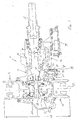
- FIGS 1 and 4 illustrate a cross-sectional view of one example of a vehicle transmission 10 that includes locking features of the present invention.
- Transmission 10 may be either a transmission front-end portion (for controlling operation of the front wheels of the vehicle) or a rear-end portion (for controlling operation of the rear wheels of the vehicle).
- Transmission 10 includes a casing 11, an input shaft 12, first and second universal joints 14, 16, a locking assembly 20, and a differential assembly 22.
- Differential assembly 22 includes a ring gear 18 and spider gears 24, 26.
- a vehicle engine (not shown) powers transmission 10 through a drive shaft 15 that rotates ring gear 18.
- Drive shaft 15 may be engaged or disengaged from input shaft 12 with a drive coupler 90 of a drive actuator assembly 92.
- Input shaft 12 includes a gear 30 fixed at one end that is configured to engage a gear surface 34 of ring gear 18. Gears 30 and 18 translate rotational motion along an axis 13 of input shaft 12 into rotational motion about an axis 37 extending between first and second universal joints 14, 16.
- Ring gear 18 includes a first outer surface 38 and first and second transverse surfaces 40, 41.
- First and second transverse surfaces 40, 41 are configured for mounting a portion of first and second slip differentials 42, 43 that are associated with differential assembly 22.
- Outer surface 38 is configured to engage a portion of locking assembly 20.
- First universal joint 16 also includes an outer surface 50 that is configured to engage the same portion of locking assembly 20 that is engaged by the outer surface 38 of ring gear 18.
- outer surfaces 38, 50 include splines or a like feature that promotes engagement between surfaces 38, 50 and surfaces of locking assembly 20.
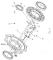
- locking assembly 20 includes a locking coupler 60 with an inner surface 62 and an outer surface 63.
- the inner surface 62 includes splines 64 or other connecting features that engage connecting features of outer surfaces 38 and 50 of ring gear 18 and second universal joint 16, respectively (see Figure 4).
- Outer surface 63 preferably includes a groove 65 or other feature configured for engagement by an actuator to move locking coupler 60 between engaged and disengaged positions.
- Locking assembly 20 also includes an actuator assembly 70 that includes a fork member 72 having a first portion 74 and a second portion 76, a first biasing member 78, a second biasing member 80, a shaft 82, and first and second retaining clips 84, 85.
- Actuation of actuator assembly 70 may be controlled by a cable (see Figures 2 and 4) or a like feature, such as an electronic solenoid (for example, see actuating solenoid 94 shown in Figure 1 that actuates drive coupler 90) that moves shaft 82 in a direction parallel to axis 37, thereby moving fork member 72 in the same direction.
- Moving fork member 72 moves locking coupler 60 between an engaged position (coupling ring gear 18 and universal joint 16 together) and a disengaged position (engaging only the ring gear 18 or the universal joint 16).
- First and second biasing members 78 and 80 are held in place on shaft 82 between first and second portions 74, 76 and first and second retaining clips 84, 85. Biasing members 78, 80 exert forces upon fork member 72 when shaft 82 is moved in a longitudinal direction, thereby urging locking coupler 60 into engaged or disengaged positions.
- Figure 1 illustrates locking coupler 60 in a disengaged position with locking coupler 60 positioned completely removed from universal joint 16 so that ring gear 18 and second universal joint 16 are disengaged from each other and can rotate freely relative to each other.
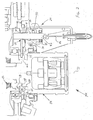
- Figure 2 shows a portion of a second example transmission 100 (similar features shown in Figures 1 and 2 having the same or similar reference numbers) wherein an outer surface 150 of second universal joint 116 is configured such that locking coupler 60, when in the disengaged position, is positioned on universal joint 116 and completely disengaged from a surface 138 of ring gear 118.
- locking coupler 60 When in the engaged position, locking coupler 60 overlaps outer surfaces 38, 138 and 50, 150, thereby locking/coupling ring gear 18, 118 to second universal joint 16, 116.
- locking coupler 60, ring gear 18, 118 and second universal joint 16, 116 When coupled together, locking coupler 60, ring gear 18, 118 and second universal joint 16, 116 must rotate together at the same speed and cannot move relative to each other, for example, due to a slipping action that may occur via slip differential 42.
- the locking assembly of the present invention provides a compact, simple way of locking a ring gear to a universal joint.
- coupler 60 is relatively thin in the direction of axis 37 so as to add very little width to the overall transmission width (for example, width (W) measured between first and second universal joints 14, 16 shown in Figure 1).
- W width
- a locking assembly of the present invention makes it possible to maximize the clearance for a vehicle that incorporates a transmission having features of the present invention.
- the position and configuration of the locking assembly relative to the universal joints also makes it possible to easily actuate the locking assembly, such as, for example, with a cable (as shown in Figures 2 and 4) or an electronic solenoid (see Figure 5) that is operated by controls that are conveniently positioned, for example on the handlebars of the vehicle, for actuation by an operator of the vehicle.
- a cable as shown in Figures 2 and 4
- an electronic solenoid see Figure 5
- first and second biasing members 78, 80 would provide tension on fork 72 that would allow the respective flat surfaces to rotate into a proper position so that flats on the inner surface of locking coupler 60 could slide onto and engage the outer surfaces 38, 138 and 50, 150.
- the splines may be slightly slanted to promote easier engagement and disengagement between locking coupler 60 and outer surfaces 38, 138 and 5 0,150.
- the locking assembly may also have different or additional features than those-shown in Figures 1-4.
- fork 72 may include only a first portion 74, or, in other embodiments, may include an end that is configured to engage a protrusion rather than a groove on outer surface 63 of locking coupler 60.
- transmissions 10 and 100 may be incorporated into either or both of a front-end and rear-end portion of a vehicle transmission.
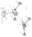
- Figure 5 illustrates front- and rear-end transmission portions 200, 300 that each include differentials (not shown) that are capable of being locked with a locking assembly 202, 302.
- Transmission portions 200, 300 include respective first and second universal joints 212, 214 and 312, 314 that are coupled to respective wheel hubs 216, 218 and 316, 318 that support wheels of the vehicle. Coupling the wheel hubs 216, 218 and 316, 318 to the respective first and second universal joints 212, 214 and 312, 314 may require additional drive shafts and universal joints.
- first universal joint 312 shown in Figure 5 may be "coupled" to hub 316 with a separate drive shaft 313 and a hub universal joint 317.
- a steering column 220 with handlebars 222 and a control panel 224 for operation of a vehicle may also be associated with transmission portions 200, 300.
- a differential control operable for locking and unlocking the differentials in transmission portions 200, 300 may include separate front and rear drive controls 226, 228 that are mounted to control panel 224, handlebars 222, or other features of the vehicle so as to be accessible by the vehicle operator, and are individually operable to lock transmission portions 200, 300.
- the differential control may be a unitary member that is capable of operating actuators of both assemblies 202, 302.
- the differential control and locking assemblies 202, 302 may be manually operated using, for example, levers or cables, or may be operated using electronic features.
- the transmission portions 200, 300 are each driven by a power source (not shown), such as an engine or motor that provides rotational power to each transmission portion 200, 300.
- Connectors 206, 306 may be used to connect the power source to an input shaft (not shown) of each transmission portion.
- a drive engagement selector assembly 210, 310 (for example, having a configuration such as assembly 92 shown in Figures 1 and 4) may be associated with each transmission portion 200, 300 to engage or disengage the power source from the transmission portion (for example, using the electrical solenoid controlled drive coupler 90 shown in Figures 1 and 4).
- a drive selector control may be used to operate the drive engagement selector assemblies 210, 310.
- the drive selector control may include separate front and rear drive controls 230, 232 that are individually operable to control the front and rear drive engagement selector assemblies 210, 310, or may be a unitary member that is capable of operating both assemblies 210, 310.
- the drive selector controls 230, 232 may be positioned on the control panel 224, handlebars 222, or at other locations on a vehicle that are accessible by the vehicle operator.
- the drive selector control and drive engagement selector assemblies 210, 310 may be manually operable using, for example, levers or cables, or may be operated using electronic features.
- the vehicle may be placed in either front wheel drive, rear wheel drive, all wheel drive, or no drive to the vehicle transmission depending on the various combinations of engagement and disengagement of the front and rear drive engagement selectors.
- power from the power source may be redirected for alternative functions associated with or separate from the vehicle such as, for example, running a generator, pump, or other accessory that can utilize the power output provided by the power source. Power from the power source can be redirected using, for example, a belt, chain, sprockets, gears, hydraulic pump, or universal joint assembly.
- front and rear differentials and limited slip differentials such as, for example, front and rear locked differentials, front and rear limited slip differentials, front locked and rear limited slip differentials, and rear locked and front limited slip differentials, depending on the locked and unlocked position of the locking coupler of the front and rear locking assemblies.
- an open differential option may be available in the transmission portion that does not include the limited slip differential when the differential of that transmission portion is not locked.
Landscapes
- Engineering & Computer Science (AREA)
- Chemical & Material Sciences (AREA)
- Combustion & Propulsion (AREA)
- Transportation (AREA)
- Mechanical Engineering (AREA)
- Retarders (AREA)
- Motor Power Transmission Devices (AREA)
- Braking Arrangements (AREA)
Abstract
Description
Claims (57)
- A locking assembly configured to couple a differential joint to first and second universal joints of a vehicle transmission assembly that are positioned at opposite sides of the differential joint, comprising;
a coupler having an external surface and an internal surface, the internal surface configured for engaging an external surface of the differential joint and an external surface of the first universal joint;
an actuator capable of engaging the external surface of the coupler to move the coupler between an engaged position and a disengaged position;
whereby in the engaged position the coupler is capable of securing the differential joint to the first universal joint such that the first and second universal joints rotate together. - The coupler of claim 1 wherein the first and second universal joints are coaxially aligned and define a transmission width, and the coupler is positioned between the first and second universal joints and has a width that contributes to the transmission width, and the coupler is configured to minimize the transmission width.
- The assembly of claim 2, wherein the first and second universal joints are configured to be movable relative to each other when the coupler is in the disengaged position.
- The assembly of claim 1 wherein the inner surface of the coupler includes splines and the outer surface of the universal joint and hub housing comprise splines configured to engage the inner surface splines of the coupler.
- The assembly of claim 1 wherein the outer surface of the coupler comprises a groove and the actuator engages the groove to move the coupler.
- The assembly of claim 1 wherein the actuator comprises:a shaft aligned substantially parallel with an axis of the first universal joint;an engagement portion secured to the shaft and extending generally perpendicular to the axis of the first universal joint, the engagement portion engaging the outer surface of the coupler;whereby linear movement of the shaft in a direction parallel to the axis of the first universal joint moves the engagement portion between a first position corresponding to the engaged position and a second position corresponding to the disengaged position.
- The assembly of claim 1 wherein the actuator is activated by a cable.
- The assembly of claim 1 wherein the actuator is activated by a lever.
- The assembly of claim 1 wherein the actuator is activated by an electronic device.
- The assembly of claim 1 wherein the first universal joint includes a constant velocity assembly.
- The assembly of claim 1 wherein the second universal joint includes a constant velocity assembly.
- The assembly of claim 1 wherein the differential joint includes a ring gear and the coupler engages an outer surface of the ring gear.
- An all-terrain vehicle, comprising:an engine; anda transmission comprising the coupler assembly of claim 1.
- The all-terrain vehicle of claim 13, wherein the transmission includes a front portion having a front differential joint and a rear portion having a rear differential joint, and each of the front and rear transmission portions comprises the coupler assembly of claim 1.
- The assembly of claim 1 wherein the actuator includes a fork-shaped portion configured to engages the external surface of the coupler.
- A method of locking an ATV transmission differential joint having an outer surface, the transmission comprising a coupler having an inner surface and an outer surface, a universal joint having an outer surface, and an actuator, the method comprising the steps of;
engaging the outer surface of the coupler with the actuator; and
activating the actuator to move the coupler between a first position wherein the inner surface of the coupler engages the outer surface of the universal joint or the outer surface of the differential, and a second position wherein the inner surface of the coupler engages the outer surface of the universal joint and the outer surface of the differential;
whereby when the coupler is in the second position the universal joint and the differential are locked together for rotation about a common axis. - The method of claim 16 wherein the inner surface of the coupler includes splines, and the outer surface of the differential joint and the outer surface of the universal joint include splines, and moving the coupler between first and second positions includes engaging the universal joint splines and the differential splines with the coupler splines.
- The method of claim 16 wherein the outer surface of the coupler includes a groove, and the engaging step includes engaging the groove with the actuator.
- The method of claim 16 further comprising the step of positioning the actuator adj acent the universal joint.
- The method of claim 16 wherein the coupler engages only the universal joint in the first position so as to rotate with the universal joint independent of the differential joint and the actuator.
- The method of claim 16 wherein the coupler engages only the differential joint in the first position so as to rotate with the differential joint independent of the universal joint and the actuator.
- The method of claim 16 wherein the hub housing includes a differential assembly having a ring gear, and engaging the universal joint with the coupler includes engaging an outer surface of the ring gear with an inner surface of the coupler.
- The method of claim 16 wherein the universal joint is a constant velocity joint.
- An all-terrain vehicle (ATV) transmission, comprising a rear transmission assembly configured to control a set of rear wheels, the rear transmission assembly having a rear differential assembly coupled to the rear wheels and a locking coupler configured to lock the rear differential assembly to fix a rotation of the rear wheels together.
- The transmission of claim 24, further comprising a front transmission assembly configured to control a set of front wheels of the ATV, the front transmission assembly having a front differential assembly coupled to the front wheels and a locking coupler configured to lock the front differential assembly to fix rotation of the front wheels together.
- The transmission of claim 24, wherein the rear differential assembly includes a ring gear and spider gears configured to provide a differential action in the rear transmission assembly.
- The transmission of claim 26, wherein the locking coupler is movable between an engaged position wherein the ring gear is effectively coupled to the rear wheels, and a disengaged position wherein the rear wheels are movable relative to each other.
- The transmission of claim 24, wherein the rear transmission assembly further comprises a limited slip differential, the limited slip differential providing limited resistance of the rear wheels relative to each other.
- The transmission of claim 26, further comprising first and second rear universal joints positioned at opposing sides of the differential assembly, each universal joint being coupled to a rear wheel, and the locking coupler configured to lock the ring gear to at least one of the first and second universal joints to lock the differential assembly.
- An all-terrain vehicle, comprising:the transmission of claim 24; andan engine providing power to the transmission assembly.
- An ATV transmission assembly, comprising:a front assembly having a front differential and a front locking coupler configured to lock the front differential; anda rear assembly having a rear differential and a rear locking coupler configured to lock the rear differential.
- The assembly of claim 31, further comprising a front limited slip differential associated with the front assembly and a rear limited slip differential associated with the rear assembly.
- The assembly of claim 31, wherein the front and rear differential assemblies each include a ring gear having an outer surface, and the transmission assembly further comprises front and rear universal joints positioned adjacent respective front and rear differentials, each universal joint having an outer surface, and the front and rear locking couplers include an inner surface configured to engage the outer surfaces of the ring gear and the universal joint to lock the respective differential.
- The assembly of claim 31, further comprising a differential control configured to operate the front and rear locking couplers for locking the respective front and rear differentials, wherein the differential control is operable to lock the front differential while the rear assembly has an open differential, lock the rear differential while the front assembly has an open differential, or lock both the front and rear differentials.
- The assembly of claim 34, wherein the front assembly further includes a front limited slip differential, the front limited slip differential being operable when the front differential is not locked.
- The assembly of claim 34, wherein the rear assembly further includes a rear limited slip differential, the rear limited slip differential being operable when the rear differential is not locked.
- The assembly of claim 31, wherein the front assembly further includes a front drive engagement selector operable to disengage the front assembly from a power source that powers the front assembly.
- The assembly of claim 31, wherein the rear assembly further includes a rear drive engagement selector operable to disengage the rear assembly from a power source that powers the rear assembly.
- The assembly of claim 34, wherein the assembly further includes a front drive engagement selector operable to disengage the front assembly from a power source, and the rear assembly further includes a rear drive engagement selector operable to disengage the rear assembly from the power source.
- The assembly of claim 39, further comprising a drive control configured to operate the front and rear drive engagement selectors, wherein the drive control is operable to disengage the front assembly from the power source, to disengage the rear assembly from the power source, or to disengage both the front and rear assemblies from the power source so that power from the power source can be directed away from the transmission assembly.
- The assembly of claim 40, wherein the drive control includes a front drive control for operating the front drive engagement selector and a rear drive control for operating the rear drive engagement selector.
- The assembly of claim 41, wherein the front and rear drive engagement selectors are electronically operated by the front and rear drive controls.
- The assembly of claim 41, wherein the front and rear drive engagement selectors are manually operated by the front and rear drive controls.
- The assembly of claim 34, wherein the differential control includes a front differential control for operating the front locking coupler to lock the front differential, and a rear differential control for operating the rear locking coupler to lock the rear differential.
- The assembly of claim 44, wherein the front and rear locking couplers are electronically operated by the front and rear differential controls.
- The assembly of claim 41, wherein the front and rear locking couplers are manually operated by the front and rear differential controls.
- A method of controlling allocation of power in an ATV, the ATV including a transmission assembly having a rear transmission portion and a rear set of wheels driven by the rear transmission portion, the rear transmission portion having a rear differential and a rear locking coupler configured to lock the rear differential, comprising the steps of:adjusting the rear locking coupler between a locked and an unlock position to control allocation of power from an engine of the ATV to the rear wheels;whereby locking the rear differential assembly with the rear locking coupler provides equal allocation of power from the engine to the rear wheels, and unlocking the rear differential assembly with the rear locking coupler facilitates variable allocation of power from the engine to each of the rear wheels.
- The method of claim 47, wherein the ATV further includes a front set of wheels and the transmission assembly further includes a front transmission portion configured to drive the front wheels, the front transmission portion having a front differential and a front locking coupler configured to lock the front differential, the method further comprising the step of:adjusting the rear locking coupler between a locked and an unlock position to control allocation of power from an engine of the ATV to the front wheels;whereby locking the front differential with the front locking coupler provides equal allocation of power from the engine to the front wheels, and unlocking the front differential with the front locking coupler facilitates variable allocation of power from the engine to each of the front wheels.
- The method of claim 47, wherein the rear transmission portion includes a limited slip differential, the limited slip differential providing limited resistance to relative motion between each of the rear wheels when the rear coupler is in an unlocked position.
- The method of claim 48, wherein the rear transmission portion includes a limited slip differential, the limited slip differential providing limited resistance to relative motion between each of the rear wheels when the rear coupler is in an unlocked position.
- An ATV transmission assembly configured to control motion of a set of rear wheels of the ATV, comprising:an input shaft;a rear differential coupled to the input shaft and the rear wheels; anda locking coupler movable between an unlocked position wherein the rear wheels are rotatable relative to each other, and a locked position wherein the differential is locked and the rear wheels are rotatable together.
- The assembly of claim 51, wherein the rear differential including a ring gear coupled to the input shaft and spider gears coupled to the ring gear.
- The assembly of claim 52, further comprising first and second universal joints coupled to the spider gears and the rear wheels.
- The assembly of claim 53, further comprising a limited slip differential operable between at least one of the first and second universal joints and the spider gears.
- The assembly of claim 54, wherein the locking coupler is configured to engage the ring gear and at least the first or second universal joint in a locked position, and is configured to engage the ring gear or the at least first or second universal joint in an unlocked position, wherein the rear wheels are free to move independent of each other subject to the limited slip differential when the locking coupler is in the unlocked position.
- A rear transmission assembly configured for powering rear wheels of an ATV, comprising:an input shaft;a ring gear coupled to the input shaft;spider gears coupled to the ring gear, the spider gears providing a differential action in the transmission;first and second universal joints coupled to the spider gears;at least one limited slip differential assembly positioned between the first or second universal joints and the spider gear;a locking coupler configured to lock the ring gear to at least the first or second universal joint;whereby when the locking coupler is in a locked position, the ring gear directly controls movement of the at least first or second universal joint, and when the locking coupler is in an unlocked position, the hubs are free to move independent of each other subject to the limited slip differential assembly.
- An ATV, comprising:a set of rear wheels;a transmission assembly including a rear differential assembly coupled to the rear wheels and a locking coupler configured to lock the rear differential assembly; andan engine configured to provide power to the transmission assembly; whereby when the rear differential is locked by the locking coupler the rear wheels rotate together, and the rear wheels rotate independent of each other when the locking coupler is not locked.
Applications Claiming Priority (2)
| Application Number | Priority Date | Filing Date | Title |
|---|---|---|---|
| US434518 | 1999-11-05 | ||
| US10/434,518 US7018317B2 (en) | 2003-05-07 | 2003-05-07 | Recreational vehicle locking differential |
Publications (3)
| Publication Number | Publication Date |
|---|---|
| EP1475264A2 true EP1475264A2 (en) | 2004-11-10 |
| EP1475264A3 EP1475264A3 (en) | 2007-12-26 |
| EP1475264B1 EP1475264B1 (en) | 2010-03-31 |
Family
ID=32990556
Family Applications (1)
| Application Number | Title | Priority Date | Filing Date |
|---|---|---|---|
| EP04445055A Expired - Lifetime EP1475264B1 (en) | 2003-05-07 | 2004-05-07 | Recreational vehicle locking differential |
Country Status (5)
| Country | Link |
|---|---|
| US (1) | US7018317B2 (en) |
| EP (1) | EP1475264B1 (en) |
| AT (1) | ATE462599T1 (en) |
| CA (1) | CA2466456A1 (en) |
| DE (1) | DE602004026244D1 (en) |
Cited By (3)
| Publication number | Priority date | Publication date | Assignee | Title |
|---|---|---|---|---|
| USD592556S1 (en) | 2007-07-03 | 2009-05-19 | Husqvarna Ab | All-terrain vehicle |
| US9587692B2 (en) | 2015-04-01 | 2017-03-07 | Akebono Brake Industry Co., Ltd | Differential for a parking brake assembly |
| US11339842B2 (en) | 2019-03-26 | 2022-05-24 | Akebono Brake Industry Co., Ltd. | Brake system with torque distributing assembly |
Families Citing this family (14)
| Publication number | Priority date | Publication date | Assignee | Title |
|---|---|---|---|---|
| WO2008157397A1 (en) * | 2007-06-15 | 2008-12-24 | Gear & Broach, Incorporated | Vehicular actuator arrangement and implementations |
| US7896771B2 (en) * | 2008-03-13 | 2011-03-01 | Honda Motor Company, Ltd. | Differential lock mechanism |
| TWI385083B (en) * | 2009-11-27 | 2013-02-11 | Kwang Yang Motor Co | Vehicle differential control device |
| US8911182B2 (en) * | 2010-05-28 | 2014-12-16 | Brandt Industries Ltd. | Agricultural equipment drive system |
| TWI402187B (en) * | 2010-07-14 | 2013-07-21 | Kwang Yang Motor Co | Vehicle power switching device |
| TWI402186B (en) * | 2010-07-14 | 2013-07-21 | Kwang Yang Motor Co | Vehicle power switching device |
| US20180065465A1 (en) | 2015-08-23 | 2018-03-08 | Arctic Cat Inc. | Off-Road Recreational Vehicle |
| US20170136874A1 (en) | 2015-08-23 | 2017-05-18 | Brian Harris | Off road vehicle |
| US11077750B2 (en) | 2017-07-12 | 2021-08-03 | Arctic Cat Inc. | Off-road utility vehicle |
| US11028883B2 (en) | 2017-11-13 | 2021-06-08 | Arctic Cat Inc. | Off-road recreational vehicle |
| US11712925B2 (en) | 2019-07-01 | 2023-08-01 | Textron Inc. | Axial plunging half-shaft assembly |
| US11926327B2 (en) * | 2020-07-30 | 2024-03-12 | Polaris Industries Inc. | All-wheel drive system and method for operating the same |
| US11827232B2 (en) * | 2021-01-22 | 2023-11-28 | Continental Automotive Systems, Inc. | High accuracy vehicle load management |
| US12496902B2 (en) | 2023-02-08 | 2025-12-16 | The Hilliard Corporation | Positive drive differential with pinion disconnect |
Family Cites Families (18)
| Publication number | Priority date | Publication date | Assignee | Title |
|---|---|---|---|---|
| GB966928A (en) * | 1962-02-27 | 1964-08-19 | Tractor Res Ltd | Improvements in or relating to control mechanism for tractors |
| US3777837A (en) * | 1971-03-02 | 1973-12-11 | M Harper | Tractor |
| US3908775A (en) * | 1974-12-16 | 1975-09-30 | Int Harvester Co | Transfer case assembly with a double duty differential |
| US4341281A (en) * | 1980-03-03 | 1982-07-27 | General Motors Corporation | Split axle drive mechanism |
| JPH0637141B2 (en) * | 1985-01-30 | 1994-05-18 | スズキ株式会社 | Two-wheel / four-wheel drive switching device |
| JPS61137149U (en) * | 1985-02-14 | 1986-08-26 | ||
| US4759232A (en) * | 1985-05-15 | 1988-07-26 | Roberts Anthony D | Locking differential |
| JPH0718480B2 (en) * | 1986-08-18 | 1995-03-06 | 本田技研工業株式会社 | Differential |
| DE3912304C2 (en) * | 1989-04-14 | 1993-11-18 | Viscodrive Gmbh | Drive arrangement for a motor vehicle |
| US5139467A (en) * | 1991-08-30 | 1992-08-18 | Auburn Gear, Inc. | Spring retainer for limited slip differentials |
| JPH05162560A (en) * | 1991-12-12 | 1993-06-29 | Hino Motors Ltd | Control device for differential limiting device |
| DE4327507C2 (en) * | 1993-08-16 | 1996-07-18 | Steyr Daimler Puch Ag | Device for controlling the clutches in the drive train of a motor vehicle |
| CA2276643A1 (en) * | 1999-06-23 | 2000-12-23 | Bombardier Inc. | Straddle-type all-terrain vehicle with progressive differential |
| JP4461582B2 (en) * | 1999-07-14 | 2010-05-12 | アイシン精機株式会社 | Driving force switching mechanism |
| US6481548B2 (en) * | 2000-08-08 | 2002-11-19 | Ntn Corporation | Two-way clutch with limited slip feature |
| US6432020B1 (en) * | 2000-08-10 | 2002-08-13 | Lazaro Rivera | Differential locking assembly |
| JP3472762B2 (en) * | 2000-12-12 | 2003-12-02 | 川崎重工業株式会社 | Differential limiter for rough terrain vehicles |
| JP4552341B2 (en) * | 2001-03-26 | 2010-09-29 | アイシン精機株式会社 | Differential equipment for four-wheel drive vehicles |
-
2003
- 2003-05-07 US US10/434,518 patent/US7018317B2/en not_active Expired - Lifetime
-
2004
- 2004-05-05 CA CA002466456A patent/CA2466456A1/en not_active Abandoned
- 2004-05-07 AT AT04445055T patent/ATE462599T1/en not_active IP Right Cessation
- 2004-05-07 EP EP04445055A patent/EP1475264B1/en not_active Expired - Lifetime
- 2004-05-07 DE DE602004026244T patent/DE602004026244D1/en not_active Expired - Lifetime
Cited By (5)
| Publication number | Priority date | Publication date | Assignee | Title |
|---|---|---|---|---|
| USD592556S1 (en) | 2007-07-03 | 2009-05-19 | Husqvarna Ab | All-terrain vehicle |
| USD592557S1 (en) | 2007-07-03 | 2009-05-19 | Husqvarna Ab | All-terrain vehicle |
| US9587692B2 (en) | 2015-04-01 | 2017-03-07 | Akebono Brake Industry Co., Ltd | Differential for a parking brake assembly |
| US11339842B2 (en) | 2019-03-26 | 2022-05-24 | Akebono Brake Industry Co., Ltd. | Brake system with torque distributing assembly |
| US11719296B2 (en) | 2019-03-26 | 2023-08-08 | Akebono Brake Industry Co., Ltd. | Brake system with torque distributing assembly |
Also Published As
| Publication number | Publication date |
|---|---|
| US7018317B2 (en) | 2006-03-28 |
| DE602004026244D1 (en) | 2010-05-12 |
| EP1475264A3 (en) | 2007-12-26 |
| CA2466456A1 (en) | 2004-11-07 |
| US20040224812A1 (en) | 2004-11-11 |
| ATE462599T1 (en) | 2010-04-15 |
| EP1475264B1 (en) | 2010-03-31 |
Similar Documents
| Publication | Publication Date | Title |
|---|---|---|
| EP1475264B1 (en) | Recreational vehicle locking differential | |
| US8123645B2 (en) | Vehicle transmission | |
| EP2093092B1 (en) | Driving force transmission device for four-wheel-drive vehicle | |
| US5098360A (en) | Differential gear with limited slip and locking mechanism | |
| US6755090B2 (en) | Retaining mechanism for transmission gears | |
| JPH1071864A (en) | Four wheel drive system and transfer case | |
| US7926624B1 (en) | Cylinder block brake | |
| GB2251275A (en) | Locking differential | |
| US8091446B2 (en) | Reverse gear locking mechanism for vehicle | |
| US7090608B2 (en) | Wheel transmission | |
| US7669686B1 (en) | Parking locking mechanism for vehicle | |
| KR20040084669A (en) | Transfer case with overdrive/underdrive shifting | |
| US11306803B2 (en) | Vehicle drive unit assembly | |
| CA2399904C (en) | Differential gearbox with locking coupling and distributor gearbox for motor vehicles equipped therewith | |
| US7758463B2 (en) | Power transmitting apparatus | |
| US6942082B1 (en) | Drive coupling | |
| US6151976A (en) | Axle driving apparatus | |
| JP2006248341A (en) | Travelling power transmission for vehicle | |
| JPH06227272A (en) | Left and right driving force adjustment device for vehicles | |
| US20080132376A1 (en) | Power transmission device | |
| KR102582846B1 (en) | Work vehicle, pto device and pto cover unit | |
| US12460717B2 (en) | Reaction cable differential interlock system and off-road vehicle including same | |
| JP3507446B2 (en) | Travel equipment for work vehicles | |
| JP2000168383A (en) | Transmission for work vehicle | |
| JP3616575B2 (en) | Travel device for work vehicle |
Legal Events
| Date | Code | Title | Description |
|---|---|---|---|
| PUAI | Public reference made under article 153(3) epc to a published international application that has entered the european phase |
Free format text: ORIGINAL CODE: 0009012 |
|
| AK | Designated contracting states |
Kind code of ref document: A2 Designated state(s): AT BE BG CH CY CZ DE DK EE ES FI FR GB GR HU IE IT LI LU MC NL PL PT RO SE SI SK TR |
|
| AX | Request for extension of the european patent |
Extension state: AL HR LT LV MK |
|
| PUAL | Search report despatched |
Free format text: ORIGINAL CODE: 0009013 |
|
| AK | Designated contracting states |
Kind code of ref document: A3 Designated state(s): AT BE BG CH CY CZ DE DK EE ES FI FR GB GR HU IE IT LI LU MC NL PL PT RO SE SI SK TR |
|
| AX | Request for extension of the european patent |
Extension state: AL HR LT LV MK |
|
| 17P | Request for examination filed |
Effective date: 20080624 |
|
| AKX | Designation fees paid |
Designated state(s): AT BE BG CH CY CZ DE DK EE ES FI FR GB GR HU IE IT LI LU MC NL PL PT RO SE SI SK TR |
|
| 17Q | First examination report despatched |
Effective date: 20081127 |
|
| GRAP | Despatch of communication of intention to grant a patent |
Free format text: ORIGINAL CODE: EPIDOSNIGR1 |
|
| GRAS | Grant fee paid |
Free format text: ORIGINAL CODE: EPIDOSNIGR3 |
|
| GRAA | (expected) grant |
Free format text: ORIGINAL CODE: 0009210 |
|
| AK | Designated contracting states |
Kind code of ref document: B1 Designated state(s): AT BE BG CH CY CZ DE DK EE ES FI FR GB GR HU IE IT LI LU MC NL PL PT RO SE SI SK TR |
|
| REG | Reference to a national code |
Ref country code: CH Ref legal event code: EP Ref country code: GB Ref legal event code: FG4D |
|
| REG | Reference to a national code |
Ref country code: IE Ref legal event code: FG4D |
|
| REF | Corresponds to: |
Ref document number: 602004026244 Country of ref document: DE Date of ref document: 20100512 Kind code of ref document: P |
|
| REG | Reference to a national code |
Ref country code: NL Ref legal event code: VDEP Effective date: 20100331 |
|
| PG25 | Lapsed in a contracting state [announced via postgrant information from national office to epo] |
Ref country code: PL Free format text: LAPSE BECAUSE OF FAILURE TO SUBMIT A TRANSLATION OF THE DESCRIPTION OR TO PAY THE FEE WITHIN THE PRESCRIBED TIME-LIMIT Effective date: 20100331 Ref country code: AT Free format text: LAPSE BECAUSE OF FAILURE TO SUBMIT A TRANSLATION OF THE DESCRIPTION OR TO PAY THE FEE WITHIN THE PRESCRIBED TIME-LIMIT Effective date: 20100331 Ref country code: FI Free format text: LAPSE BECAUSE OF FAILURE TO SUBMIT A TRANSLATION OF THE DESCRIPTION OR TO PAY THE FEE WITHIN THE PRESCRIBED TIME-LIMIT Effective date: 20100331 Ref country code: SI Free format text: LAPSE BECAUSE OF FAILURE TO SUBMIT A TRANSLATION OF THE DESCRIPTION OR TO PAY THE FEE WITHIN THE PRESCRIBED TIME-LIMIT Effective date: 20100331 |
|
| PG25 | Lapsed in a contracting state [announced via postgrant information from national office to epo] |
Ref country code: SE Free format text: LAPSE BECAUSE OF FAILURE TO SUBMIT A TRANSLATION OF THE DESCRIPTION OR TO PAY THE FEE WITHIN THE PRESCRIBED TIME-LIMIT Effective date: 20100331 Ref country code: RO Free format text: LAPSE BECAUSE OF FAILURE TO SUBMIT A TRANSLATION OF THE DESCRIPTION OR TO PAY THE FEE WITHIN THE PRESCRIBED TIME-LIMIT Effective date: 20100331 Ref country code: NL Free format text: LAPSE BECAUSE OF FAILURE TO SUBMIT A TRANSLATION OF THE DESCRIPTION OR TO PAY THE FEE WITHIN THE PRESCRIBED TIME-LIMIT Effective date: 20100331 Ref country code: ES Free format text: LAPSE BECAUSE OF FAILURE TO SUBMIT A TRANSLATION OF THE DESCRIPTION OR TO PAY THE FEE WITHIN THE PRESCRIBED TIME-LIMIT Effective date: 20100712 Ref country code: EE Free format text: LAPSE BECAUSE OF FAILURE TO SUBMIT A TRANSLATION OF THE DESCRIPTION OR TO PAY THE FEE WITHIN THE PRESCRIBED TIME-LIMIT Effective date: 20100331 Ref country code: CY Free format text: LAPSE BECAUSE OF FAILURE TO SUBMIT A TRANSLATION OF THE DESCRIPTION OR TO PAY THE FEE WITHIN THE PRESCRIBED TIME-LIMIT Effective date: 20100331 Ref country code: BE Free format text: LAPSE BECAUSE OF FAILURE TO SUBMIT A TRANSLATION OF THE DESCRIPTION OR TO PAY THE FEE WITHIN THE PRESCRIBED TIME-LIMIT Effective date: 20100331 |
|
| PG25 | Lapsed in a contracting state [announced via postgrant information from national office to epo] |
Ref country code: SK Free format text: LAPSE BECAUSE OF FAILURE TO SUBMIT A TRANSLATION OF THE DESCRIPTION OR TO PAY THE FEE WITHIN THE PRESCRIBED TIME-LIMIT Effective date: 20100331 Ref country code: CZ Free format text: LAPSE BECAUSE OF FAILURE TO SUBMIT A TRANSLATION OF THE DESCRIPTION OR TO PAY THE FEE WITHIN THE PRESCRIBED TIME-LIMIT Effective date: 20100331 |
|
| PG25 | Lapsed in a contracting state [announced via postgrant information from national office to epo] |
Ref country code: MC Free format text: LAPSE BECAUSE OF NON-PAYMENT OF DUE FEES Effective date: 20100531 |
|
| REG | Reference to a national code |
Ref country code: CH Ref legal event code: PL |
|
| PG25 | Lapsed in a contracting state [announced via postgrant information from national office to epo] |
Ref country code: DK Free format text: LAPSE BECAUSE OF FAILURE TO SUBMIT A TRANSLATION OF THE DESCRIPTION OR TO PAY THE FEE WITHIN THE PRESCRIBED TIME-LIMIT Effective date: 20100331 Ref country code: PT Free format text: LAPSE BECAUSE OF FAILURE TO SUBMIT A TRANSLATION OF THE DESCRIPTION OR TO PAY THE FEE WITHIN THE PRESCRIBED TIME-LIMIT Effective date: 20100802 |
|
| PLBE | No opposition filed within time limit |
Free format text: ORIGINAL CODE: 0009261 |
|
| STAA | Information on the status of an ep patent application or granted ep patent |
Free format text: STATUS: NO OPPOSITION FILED WITHIN TIME LIMIT |
|
| GBPC | Gb: european patent ceased through non-payment of renewal fee |
Effective date: 20100630 |
|
| PG25 | Lapsed in a contracting state [announced via postgrant information from national office to epo] |
Ref country code: CH Free format text: LAPSE BECAUSE OF NON-PAYMENT OF DUE FEES Effective date: 20100531 Ref country code: LI Free format text: LAPSE BECAUSE OF NON-PAYMENT OF DUE FEES Effective date: 20100531 |
|
| 26N | No opposition filed |
Effective date: 20110104 |
|
| PG25 | Lapsed in a contracting state [announced via postgrant information from national office to epo] |
Ref country code: IT Free format text: LAPSE BECAUSE OF FAILURE TO SUBMIT A TRANSLATION OF THE DESCRIPTION OR TO PAY THE FEE WITHIN THE PRESCRIBED TIME-LIMIT Effective date: 20100331 |
|
| PG25 | Lapsed in a contracting state [announced via postgrant information from national office to epo] |
Ref country code: IE Free format text: LAPSE BECAUSE OF NON-PAYMENT OF DUE FEES Effective date: 20100507 |
|
| PG25 | Lapsed in a contracting state [announced via postgrant information from national office to epo] |
Ref country code: GB Free format text: LAPSE BECAUSE OF NON-PAYMENT OF DUE FEES Effective date: 20100630 |
|
| PG25 | Lapsed in a contracting state [announced via postgrant information from national office to epo] |
Ref country code: BG Free format text: LAPSE BECAUSE OF FAILURE TO SUBMIT A TRANSLATION OF THE DESCRIPTION OR TO PAY THE FEE WITHIN THE PRESCRIBED TIME-LIMIT Effective date: 20100331 Ref country code: LU Free format text: LAPSE BECAUSE OF NON-PAYMENT OF DUE FEES Effective date: 20100507 Ref country code: HU Free format text: LAPSE BECAUSE OF FAILURE TO SUBMIT A TRANSLATION OF THE DESCRIPTION OR TO PAY THE FEE WITHIN THE PRESCRIBED TIME-LIMIT Effective date: 20101001 |
|
| PG25 | Lapsed in a contracting state [announced via postgrant information from national office to epo] |
Ref country code: TR Free format text: LAPSE BECAUSE OF FAILURE TO SUBMIT A TRANSLATION OF THE DESCRIPTION OR TO PAY THE FEE WITHIN THE PRESCRIBED TIME-LIMIT Effective date: 20100331 |
|
| PG25 | Lapsed in a contracting state [announced via postgrant information from national office to epo] |
Ref country code: BG Free format text: LAPSE BECAUSE OF FAILURE TO SUBMIT A TRANSLATION OF THE DESCRIPTION OR TO PAY THE FEE WITHIN THE PRESCRIBED TIME-LIMIT Effective date: 20100630 |
|
| PG25 | Lapsed in a contracting state [announced via postgrant information from national office to epo] |
Ref country code: GR Free format text: LAPSE BECAUSE OF FAILURE TO SUBMIT A TRANSLATION OF THE DESCRIPTION OR TO PAY THE FEE WITHIN THE PRESCRIBED TIME-LIMIT Effective date: 20100331 |
|
| PGFP | Annual fee paid to national office [announced via postgrant information from national office to epo] |
Ref country code: DE Payment date: 20140514 Year of fee payment: 11 |
|
| PGFP | Annual fee paid to national office [announced via postgrant information from national office to epo] |
Ref country code: FR Payment date: 20140514 Year of fee payment: 11 |
|
| REG | Reference to a national code |
Ref country code: DE Ref legal event code: R119 Ref document number: 602004026244 Country of ref document: DE |
|
| REG | Reference to a national code |
Ref country code: FR Ref legal event code: ST Effective date: 20160129 |
|
| PG25 | Lapsed in a contracting state [announced via postgrant information from national office to epo] |
Ref country code: DE Free format text: LAPSE BECAUSE OF NON-PAYMENT OF DUE FEES Effective date: 20151201 |
|
| PG25 | Lapsed in a contracting state [announced via postgrant information from national office to epo] |
Ref country code: FR Free format text: LAPSE BECAUSE OF NON-PAYMENT OF DUE FEES Effective date: 20150601 |