EP1475158A1 - Shielded electrode - Google Patents
Shielded electrode Download PDFInfo
- Publication number
- EP1475158A1 EP1475158A1 EP04006835A EP04006835A EP1475158A1 EP 1475158 A1 EP1475158 A1 EP 1475158A1 EP 04006835 A EP04006835 A EP 04006835A EP 04006835 A EP04006835 A EP 04006835A EP 1475158 A1 EP1475158 A1 EP 1475158A1
- Authority
- EP
- European Patent Office
- Prior art keywords
- electrode
- output port
- sleeve
- dispensing device
- coating material
- Prior art date
- Legal status (The legal status is an assumption and is not a legal conclusion. Google has not performed a legal analysis and makes no representation as to the accuracy of the status listed.)
- Withdrawn
Links
- 239000000463 material Substances 0.000 claims abstract description 45
- 239000011248 coating agent Substances 0.000 claims abstract description 41
- 238000000576 coating method Methods 0.000 claims abstract description 41
- 239000003989 dielectric material Substances 0.000 claims description 13
- 238000000034 method Methods 0.000 claims description 9
- 230000008878 coupling Effects 0.000 claims description 4
- 238000010168 coupling process Methods 0.000 claims description 4
- 238000005859 coupling reaction Methods 0.000 claims description 4
- 238000012360 testing method Methods 0.000 description 13
- 229910052751 metal Inorganic materials 0.000 description 6
- 239000002184 metal Substances 0.000 description 6
- ATUOYWHBWRKTHZ-UHFFFAOYSA-N Propane Chemical compound CCC ATUOYWHBWRKTHZ-UHFFFAOYSA-N 0.000 description 4
- -1 for example Polymers 0.000 description 4
- DHKHKXVYLBGOIT-UHFFFAOYSA-N 1,1-Diethoxyethane Chemical compound CCOC(C)OCC DHKHKXVYLBGOIT-UHFFFAOYSA-N 0.000 description 3
- 239000004696 Poly ether ether ketone Substances 0.000 description 3
- 239000011354 acetal resin Substances 0.000 description 3
- 229920002530 polyetherether ketone Polymers 0.000 description 3
- 229920006324 polyoxymethylene Polymers 0.000 description 3
- 229920001343 polytetrafluoroethylene Polymers 0.000 description 3
- 239000004810 polytetrafluoroethylene Substances 0.000 description 3
- 229920004943 Delrin® Polymers 0.000 description 2
- 239000000853 adhesive Substances 0.000 description 2
- 230000001070 adhesive effect Effects 0.000 description 2
- 238000013459 approach Methods 0.000 description 2
- 238000000889 atomisation Methods 0.000 description 2
- 230000005684 electric field Effects 0.000 description 2
- 239000002245 particle Substances 0.000 description 2
- 239000001294 propane Substances 0.000 description 2
- 238000011160 research Methods 0.000 description 2
- 239000011347 resin Substances 0.000 description 2
- 229920005989 resin Polymers 0.000 description 2
- 239000004677 Nylon Substances 0.000 description 1
- 239000004952 Polyamide Substances 0.000 description 1
- 239000004830 Super Glue Substances 0.000 description 1
- 239000004809 Teflon Substances 0.000 description 1
- 229920006362 Teflon® Polymers 0.000 description 1
- RTAQQCXQSZGOHL-UHFFFAOYSA-N Titanium Chemical compound [Ti] RTAQQCXQSZGOHL-UHFFFAOYSA-N 0.000 description 1
- 230000000712 assembly Effects 0.000 description 1
- 238000000429 assembly Methods 0.000 description 1
- 238000009503 electrostatic coating Methods 0.000 description 1
- 238000005421 electrostatic potential Methods 0.000 description 1
- FGBJXOREULPLGL-UHFFFAOYSA-N ethyl cyanoacrylate Chemical compound CCOC(=O)C(=C)C#N FGBJXOREULPLGL-UHFFFAOYSA-N 0.000 description 1
- 238000004880 explosion Methods 0.000 description 1
- 239000002360 explosive Substances 0.000 description 1
- 239000007788 liquid Substances 0.000 description 1
- 239000000203 mixture Substances 0.000 description 1
- 229920001778 nylon Polymers 0.000 description 1
- 229920002647 polyamide Polymers 0.000 description 1
- 239000010936 titanium Substances 0.000 description 1
- 229910052719 titanium Inorganic materials 0.000 description 1
- 230000009466 transformation Effects 0.000 description 1
- 238000009966 trimming Methods 0.000 description 1
Images

Classifications
-
- B—PERFORMING OPERATIONS; TRANSPORTING
- B05—SPRAYING OR ATOMISING IN GENERAL; APPLYING FLUENT MATERIALS TO SURFACES, IN GENERAL
- B05B—SPRAYING APPARATUS; ATOMISING APPARATUS; NOZZLES
- B05B5/00—Electrostatic spraying apparatus; Spraying apparatus with means for charging the spray electrically; Apparatus for spraying liquids or other fluent materials by other electric means
- B05B5/025—Discharge apparatus, e.g. electrostatic spray guns
- B05B5/053—Arrangements for supplying power, e.g. charging power
- B05B5/0533—Electrodes specially adapted therefor; Arrangements of electrodes
-
- F—MECHANICAL ENGINEERING; LIGHTING; HEATING; WEAPONS; BLASTING
- F24—HEATING; RANGES; VENTILATING
- F24C—DOMESTIC STOVES OR RANGES ; DETAILS OF DOMESTIC STOVES OR RANGES, OF GENERAL APPLICATION
- F24C3/00—Stoves or ranges for gaseous fuels
- F24C3/12—Arrangement or mounting of control or safety devices
-
- F—MECHANICAL ENGINEERING; LIGHTING; HEATING; WEAPONS; BLASTING
- F16—ENGINEERING ELEMENTS AND UNITS; GENERAL MEASURES FOR PRODUCING AND MAINTAINING EFFECTIVE FUNCTIONING OF MACHINES OR INSTALLATIONS; THERMAL INSULATION IN GENERAL
- F16K—VALVES; TAPS; COCKS; ACTUATING-FLOATS; DEVICES FOR VENTING OR AERATING
- F16K17/00—Safety valves; Equalising valves, e.g. pressure relief valves
- F16K17/003—Safety valves; Equalising valves, e.g. pressure relief valves reacting to pressure and temperature
-
- B—PERFORMING OPERATIONS; TRANSPORTING
- B05—SPRAYING OR ATOMISING IN GENERAL; APPLYING FLUENT MATERIALS TO SURFACES, IN GENERAL
- B05B—SPRAYING APPARATUS; ATOMISING APPARATUS; NOZZLES
- B05B5/00—Electrostatic spraying apparatus; Spraying apparatus with means for charging the spray electrically; Apparatus for spraying liquids or other fluent materials by other electric means
- B05B5/025—Discharge apparatus, e.g. electrostatic spray guns
- B05B5/053—Arrangements for supplying power, e.g. charging power
- B05B5/0531—Power generators
-
- F—MECHANICAL ENGINEERING; LIGHTING; HEATING; WEAPONS; BLASTING
- F24—HEATING; RANGES; VENTILATING
- F24C—DOMESTIC STOVES OR RANGES ; DETAILS OF DOMESTIC STOVES OR RANGES, OF GENERAL APPLICATION
- F24C3/00—Stoves or ranges for gaseous fuels
- F24C3/008—Ranges
Definitions
- This invention relates to electrostatically aided atomization and coating of articles with charged particles. It is disclosed in the context of certain types of coating material dispensers. However, it is believed to be useful in a wide range of coating dispensing applications.
- electrically conductive and “electrically non-insulative” refer to a broad range of conductivities electrically more conductive than materials described as “electrically non-conductive” and “electrically insulative.” Terms such as “front,” “rear,” “top,” “bottom,” and the like are used for convenience in explanation and understanding of the invention only, and are not intended to be, nor should they be considered as, used in any limiting sense.
- the FM standard includes protocols for the testing of both manual equipment (for example, hand held coating atomizing and dispensing guns--the FM standard, chapter 5) and automatic equipment (for example, atomizers mounted on robot arms--the FM standard, chapter 6).
- manual equipment for example, hand held coating atomizing and dispensing guns--the FM standard, chapter 5
- automatic equipment for example, atomizers mounted on robot arms--the FM standard, chapter 6
- To achieve FM approval the equipment must, inter alia, pass this test.
- the FM standard has caused considerable research and improvement in the safety of electrostatic coating systems.
- a coating material dispensing device includes an output port through which the coating material is dispensed and an electrode projecting from the dispensing device adjacent the output port for transferring electrical charge to the coating material dispensed through the output port.
- the coating material dispensing device further includes a shield for shielding a portion of the electrode adjacent the electrode's connection to the dispensing device.
- the output port includes an axis.
- the electrode is offset from the axis.
- the electrode comprises a needle-like electrode of metal or other non-insulative material.
- the shield comprises a sleeve of a dielectric material.
- the sleeve is coupled to the dispensing device at a first end.
- the electrode projects from a second end of the sleeve remote from the first end.
- a method for dispensing coating material includes providing a dispensing device, providing on the dispensing device an output port, and dispensing coating material through the output port.
- An electrode is provided adjacent the output port for transferring electrical charge to the coating material dispensed through the output port. A portion of the electrode adjacent the dispensing device is shielded.
- providing an output port includes providing an output port having an axis.
- Providing an electrode includes providing an electrode offset from the axis.
- providing an electrode comprises providing a needle-like electrode of metal or other non-insulative material.
- shielding a portion of the electrode comprises providing a sleeve of a dielectric material, coupling the sleeve to the dispensing device at a first end, and permitting the electrode to project from a second end of the sleeve remote from the first end.
- a coating material dispensing system includes a device having an output port through which the coating material is dispensed and an electrode projecting from the dispensing device adjacent the output port.
- An electrical supply is coupled to the electrode.
- the electrode transfers the electrical charge to the coating material dispensed through the output port.
- a shield is provided for shielding a portion of the electrode adjacent its connection to the dispensing device.
- the output port includes an axis.
- the electrode is offset from the axis.
- the electrode comprises a needle-like electrode of metal or other non-insulative material.
- the shield comprises a sleeve of a dielectric material.
- the sleeve is coupled to the dispensing device at a first end.
- the electrode projects from a second end of the sleeve remote from the first end.
- the electrical supply comprises a relatively higher-magnitude DC electrical potential supply.
- the electrical supply comprises a relatively lower DC electrical potential supply.
- the electrical supply comprises a relatively lower AC electrical potential supply.
- a method for dispensing coating material includes providing a device having an output port through which the coating material is dispensed, providing an electrical supply, providing an electrode adjacent the output port, coupling the electrode to the electrical supply, transferring electrical charge to the coating material dispensed through the output port, and shielding a portion of the electrode adjacent its connection to the dispensing device.
- providing an output port includes providing an output port having an axis.
- Providing an electrode includes providing an electrode which is offset from the axis.
- providing an electrode includes providing a needle-like electrode of metal or other non-insulative material.
- shielding a portion of the electrode comprises providing a sleeve of a dielectric material.
- the method further includes coupling the sleeve to the dispensing device at a first end and permitting the electrode to project from a second end of the sleeve remote from the first end.
- providing an electrical supply comprises providing a relatively high-magnitude DC electrical potential supply.
- providing an electrical supply comprises providing a relatively low DC electrical potential supply.
- providing an electrical supply comprises providing a relatively low AC electrical potential supply.
- a method for preparing a coating material dispensing device for a test in which a conductive object is made to approach the electrode to promote electrical discharge between the electrode and the conductive object.
- the coating material dispensing device has an output port through which coating material is to be dispensed from the coating material dispensing device. Adjacent the output port, an electrode projects from the coating material dispensing device.
- the method includes placing a shield of a dielectric material around the electrode and establishing a potential difference between the electrode and the conductive object.
- the electrode comprises a needle-like electrode.
- Placing a shield of a dielectric material around the electrode includes placing a sleeve of dielectric material around the electrode and attaching an end of the sleeve to the dispensing device.
- placing a sleeve of a dielectric material around the electrode and attaching an end of the sleeve to the dispensing device together include leaving an unshielded region remote from the attachment of the electrode to the dispensing device.
- a coating material dispensing device (hereinafter sometimes "gun") 22 illustratively is of the general type of the Ransburg model REA 3, REA 4, REA 70, REA 90, REM and M-90 guns, available from ITW Ransburg, 320 Phillips Avenue, Toledo, Ohio, 43612-1493.
- the coating material to be atomized and dispensed is supplied from a source 24 to an input port 26 of the gun 22, and is supplied through a passageway (not shown) in the gun 22 to a trigger 30-operated valve (not shown) at the front of the gun 22.
- Other services which the gun 22 may require to operate include, for example, relatively higher-magnitude (for example, -85 KV) DC electrical potential, relatively lower (for example, + or - 12V or + or - 24V) AC or DC electrical potential, relatively higher pressure (for example, 100 p. s. i.) compressed air and relatively lower pressure (for example, 20 p. s. i.) compressed air from one or more sources.
- relatively higher-magnitude for example, -85 KV
- DC electrical potential for example, relatively lower (for example, + or - 12V or + or - 24V) AC or DC electrical potential
- relatively higher pressure for example, 100 p. s. i.
- relatively lower pressure for example, 20 p. s. i.
- Relatively lower potential DC electrical potential may be supplied to gun 22, but an inverter must be incorporated into power supply 33 to convert the low DC voltage to AC for step-up transformation and multiplication.
- Examples of power supplies 33 include the systems embodied in the REA-90 and REA-90L guns available from ITW Ransburg, 320 Phillips Avenue, Toledo, Ohio, 43612-1493. Other types of power supplies may also be used.
- in-gun power supplies which include compressed-gas driven turbines which drive generators or alternators, the outputs of which are supplied directly to a step-up transformer and Cockcroft-Walton multiplier, in the case of an in-gun alternator, or through an inverter to a step-up transformer and Cockcroft-Walton multiplier, in the case of an in-gun DC generator.
- the coating material is dispensed under the control of the trigger 30 through a nozzle 34 of the gun 22, where the liquid is atomized and dispensed.
- the output of the power supply 33 is coupled through circuitry within gun 22 to a needle-like charging electrode (sometimes hereinafter “needle electrode") 40 mounted on an air cap 36 at the front of gun 22.
- Air cap 36 houses nozzle 34.
- An electrical field is thereby established between needle electrode 40 and nearby grounded objects, such as, for example, a grounded article 42 to be coated by coating material dispensed from gun 22.
- the atomized particles of coating material are electrically charged by electrons flowing from the needle electrode 40 and migrate down the electrical field to the article 42 and deposit on article 42, all in accordance with established principles.
- the area around the nozzle 34 is probed with a grounded one inch (about 2.5 cm) diameter sphere 43 while high-magnitude electrostatic potential is being supplied to needle electrode 40.
- Corona discharge will be apparent between the sphere 43 and the needle electrode 40 as the sphere 43 is moved, for example, from the rear of the gun 22 forward toward the air cap 36 and into the vicinity of the needle electrode 40.
- a relatively high energy corona discharge will be apparent in the region of the base of the needle electrode 40, that is, where the needle electrode 40 projects forward from the front surface of the air cap 36, a relatively high energy corona discharge will be apparent.
- the terminals of this discharge will be a small area of the surface of the sphere 43 and the base of the needle electrode 40.
- the relatively high energy discharge in such prior art assemblies is often enough to ignite the propane in air mixture mandated by the FM standard. This, of course, constitutes a failure under the FM standard.
- a sleeve 46 of a dielectric material is provided around the needle electrode 40, shielding the needle electrode somewhat against high energy electrical discharge from the base of the needle electrode 40 toward a grounded metal sphere 43 which is made to approach the front of gun 22 from any arbitrary angle during such a test.
- the discharge which is established from such a shielded needle electrode 40 appears to originate from an unshielded region 48 of the needle electrode 40 at and adjacent the tip of the electrode 40.
- a gun 22 with such a needle electrode 40 shielded by such a sleeve 46 experiences fewer high energy discharges, resulting in improved results from tests such as the test mandated by the FM standard.
- needle electrode 40 is a .016 inch (about .4 mm) diameter titanium needle electrode which projects a distance of about .25 inch (about 6.4 mm) forward from the front of air cap 36.
- the air cap itself is constructed from black type 150 E Delrin brand acetal resin.
- the sleeve 46 is a length of any suitably dielectric material, such as polyetheretherketone (PEEK) resin, acetal resin, for example, Delrin brand acetal resin, polytetrafluoroethylene (PTFE), for example, Teflon brand PTFE, polyamide, for example, nylon, or the like.
- PEEK polyetheretherketone
- acetal resin for example, Delrin brand acetal resin
- PTFE polytetrafluoroethylene
- Teflon brand PTFE polyamide, for example, nylon, or the like.
- Sleeve 46 has an inside diameter of about .020 inch (about .5 mm) and an outside diameter of about .0625 inch (about 1.6 mm).
- the sleeve 46 is cut to a length permitting exposure 48 of about .05 inch (about 1.27 mm) of the length of needle electrode 40.
- Coating the same portion (or all) of the length of the needle electrode 40 with a material (for example, a conformal coating) of any suitable thickness, for example, .001 inch (about .03 mm) may also yield acceptable results. If all of the needle electrode 40 is coated, trimming the end of the coated needle electrode exposes the tip of the needle electrode to serve as a point from which charging can occur.
- Sleeve 46 may be glued to air cap 36 around the base of electrode 40 using an adhesive appropriate for the material from which the sleeve 46 is formed.
- an adhesive appropriate for the material from which the sleeve 46 is formed.
- a cyanoacrylate adhesive such as Zip Grip 4495 adhesive available from ITW Devcon, 30 Endicott Street, Danvers, MA 01923 may be applied on the outside of sleeve 46.
- the sleeve 46 may be press-fitted onto the needle electrode 40 and/or into a recess (not shown) surrounding the base of the needle electrode 40 on the air cap 36.
- needle electrode 40 is mounted offset from the air cap 36 axis, it should be understood that the invention may also be used on a needle electrode that projects from generally the center of the air cap 36, that is, from the axis of the gun 22 barrel.
- the dielectric shield provided by sleeve 46 means that the discharge must travel a greater distance, from the exposed tip 48 of the needle electrode 40 to any nearby ground, such as the sphere 43, or the discharge must overcome the dielectric strength of the sleeve 46 to travel the same distance as it would travel without the sleeve 46 present.
Landscapes
- Engineering & Computer Science (AREA)
- General Engineering & Computer Science (AREA)
- Mechanical Engineering (AREA)
- Chemical & Material Sciences (AREA)
- Combustion & Propulsion (AREA)
- Electrostatic Spraying Apparatus (AREA)
- Application Of Or Painting With Fluid Materials (AREA)
- Coating Apparatus (AREA)
- Closures For Containers (AREA)
Abstract
Description
- This invention relates to electrostatically aided atomization and coating of articles with charged particles. It is disclosed in the context of certain types of coating material dispensers. However, it is believed to be useful in a wide range of coating dispensing applications.
- As used in this application, terms such as "electrically conductive" and "electrically non-insulative" refer to a broad range of conductivities electrically more conductive than materials described as "electrically non-conductive" and "electrically insulative." Terms such as "front," "rear," "top," "bottom," and the like are used for convenience in explanation and understanding of the invention only, and are not intended to be, nor should they be considered as, used in any limiting sense.
- Automatic and handheld coating material dispensing devices of various types are well known. There are, for example, the guns illustrated and described in U. S. Patents: 3,169,882; 3,169,883; 4,002,777; and, 4,285,446. There are also the Ransburg model REA 3, REA 4, REA 70, REA 90, REM and M-90 guns, all available from ITW Ransburg, 320 Phillips Avenue, Toledo, Ohio, 43612-1493. No representation is intended by this listing that a thorough search of all material prior art has been conducted, or that no better art than that listed is available, or that the listed items are material to patentability. Nor should any such representation be inferred.
- Standards for testing electrostatically aided coating material atomization and dispensing equipment have been promulgated by a number of testing agencies in various countries. Illustrative of such standards is the Electrostatic Finishing Equipment Approval Standard, Class Number 7260, promulgated by Factory Mutual Research Corporation (the FM standard).
- The FM standard includes protocols for the testing of both manual equipment (for example, hand held coating atomizing and dispensing guns--the FM standard, chapter 5) and automatic equipment (for example, atomizers mounted on robot arms--the FM standard, chapter 6). Among the tests in both cases is a test in which the equipment at operating voltage is probed using a grounded metal sphere having a diameter of one inch (about 2.5 cm). This test takes place in an explosive atmosphere of propane in air. An explosion is a failed test. To achieve FM approval, the equipment must, inter alia, pass this test. The FM standard has caused considerable research and improvement in the safety of electrostatic coating systems.
- According to an aspect of the invention, a coating material dispensing device includes an output port through which the coating material is dispensed and an electrode projecting from the dispensing device adjacent the output port for transferring electrical charge to the coating material dispensed through the output port The coating material dispensing device further includes a shield for shielding a portion of the electrode adjacent the electrode's connection to the dispensing device.
- Illustratively according to this aspect of the invention, the output port includes an axis. The electrode is offset from the axis.
- Further illustratively according to this aspect of the invention, the electrode comprises a needle-like electrode of metal or other non-insulative material.
- Additionally illustratively according to this aspect of the invention, the shield comprises a sleeve of a dielectric material. The sleeve is coupled to the dispensing device at a first end. The electrode projects from a second end of the sleeve remote from the first end.
- According to another aspect of the invention, a method for dispensing coating material includes providing a dispensing device, providing on the dispensing device an output port, and dispensing coating material through the output port. An electrode is provided adjacent the output port for transferring electrical charge to the coating material dispensed through the output port. A portion of the electrode adjacent the dispensing device is shielded.
- Illustratively according to this aspect of the invention, providing an output port includes providing an output port having an axis. Providing an electrode includes providing an electrode offset from the axis.
- Further illustratively according to this aspect of the invention, providing an electrode comprises providing a needle-like electrode of metal or other non-insulative material.
- Additionally illustratively according to this aspect of the invention, shielding a portion of the electrode comprises providing a sleeve of a dielectric material, coupling the sleeve to the dispensing device at a first end, and permitting the electrode to project from a second end of the sleeve remote from the first end.
- According to another aspect of the invention, a coating material dispensing system includes a device having an output port through which the coating material is dispensed and an electrode projecting from the dispensing device adjacent the output port. An electrical supply is coupled to the electrode. The electrode transfers the electrical charge to the coating material dispensed through the output port. A shield is provided for shielding a portion of the electrode adjacent its connection to the dispensing device.
- Illustratively according to this aspect of the invention, the output port includes an axis. The electrode is offset from the axis.
- Further illustratively according to this aspect of the invention, the electrode comprises a needle-like electrode of metal or other non-insulative material.
- Additionally illustratively according to this aspect of the invention, the shield comprises a sleeve of a dielectric material. The sleeve is coupled to the dispensing device at a first end. The electrode projects from a second end of the sleeve remote from the first end.
- Illustratively according to this aspect of the invention, the electrical supply comprises a relatively higher-magnitude DC electrical potential supply.
- Alternatively illustratively according to this aspect of the invention, the electrical supply comprises a relatively lower DC electrical potential supply.
- Further alternatively illustratively according to this aspect of the invention, the electrical supply comprises a relatively lower AC electrical potential supply.
- According to another aspect of the invention, a method for dispensing coating material includes providing a device having an output port through which the coating material is dispensed, providing an electrical supply, providing an electrode adjacent the output port, coupling the electrode to the electrical supply, transferring electrical charge to the coating material dispensed through the output port, and shielding a portion of the electrode adjacent its connection to the dispensing device.
- Illustratively according to this aspect of the invention, providing an output port includes providing an output port having an axis. Providing an electrode includes providing an electrode which is offset from the axis.
- Further illustratively according to this aspect of the invention, providing an electrode includes providing a needle-like electrode of metal or other non-insulative material.
- Additionally illustratively according to this aspect of the invention, shielding a portion of the electrode comprises providing a sleeve of a dielectric material. The method further includes coupling the sleeve to the dispensing device at a first end and permitting the electrode to project from a second end of the sleeve remote from the first end.
- Illustratively according to this aspect of the invention, providing an electrical supply comprises providing a relatively high-magnitude DC electrical potential supply.
- Alternatively illustratively according to this aspect of the invention, providing an electrical supply comprises providing a relatively low DC electrical potential supply.
- Further alternatively illustratively according to this aspect of the invention, providing an electrical supply comprises providing a relatively low AC electrical potential supply.
- According to another aspect of the invention, a method is provided for preparing a coating material dispensing device for a test in which a conductive object is made to approach the electrode to promote electrical discharge between the electrode and the conductive object. The coating material dispensing device has an output port through which coating material is to be dispensed from the coating material dispensing device. Adjacent the output port, an electrode projects from the coating material dispensing device. The method includes placing a shield of a dielectric material around the electrode and establishing a potential difference between the electrode and the conductive object.
- Illustratively according to this aspect of the invention, the electrode comprises a needle-like electrode. Placing a shield of a dielectric material around the electrode includes placing a sleeve of dielectric material around the electrode and attaching an end of the sleeve to the dispensing device.
- Further illustratively according to this aspect of the invention, placing a sleeve of a dielectric material around the electrode and attaching an end of the sleeve to the dispensing device together include leaving an unshielded region remote from the attachment of the electrode to the dispensing device.
- The invention may best be understood by referring to the following description and accompanying drawings which illustrate the invention. In the drawings:
- Fig. 1 illustrates a side elevational view of an atomizer of a type which is capable of incorporating the invention, with other components of a system incorporating the atomizer illustrated diagrammatically;
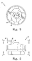
- Fig. 2 illustrates an enlarged view of a detail of the system illustrated in Fig. 1;
- Fig. 3 illustrates a front elevational view, taken generally along section lines 3-3 of Fig. 2, of the detail illustrated in Figs. 1-2;
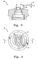
- Fig. 4 illustrates a rear elevational view, taken generally along section lines 4-4 of Fig. 2, of the detail illustrated in Figs. 1-3; and,
- Fig. 5 illustrates a sectional view, taken generally along section lines 5-5 of Fig. 4, of the detail illustrated in Figs. 1-4.
-
- Referring to Fig. 1, in a typical implementation, a coating material dispensing device (hereinafter sometimes "gun") 22 illustratively is of the general type of the
Ransburg model REA 3, REA 4, REA 70, REA 90, REM and M-90 guns, available from ITW Ransburg, 320 Phillips Avenue, Toledo, Ohio, 43612-1493. The coating material to be atomized and dispensed is supplied from asource 24 to aninput port 26 of the gun 22, and is supplied through a passageway (not shown) in the gun 22 to a trigger 30-operated valve (not shown) at the front of the gun 22. - Other services which the gun 22 may require to operate include, for example, relatively higher-magnitude (for example, -85 KV) DC electrical potential, relatively lower (for example, + or - 12V or + or - 24V) AC or DC electrical potential, relatively higher pressure (for example, 100 p. s. i.) compressed air and relatively lower pressure (for example, 20 p. s. i.) compressed air from one or more sources. Two
such sources Source 29 illustratively is a source of compressed air at a desired pressure.Source 31 illustratively is a source of relatively lower AC electrical potential which is supplied to, for example, a step-up transformer and Cockcroft-Waltonmultiplier power supply 33 with which gun 22 is equipped. Relatively lower potential DC electrical potential may be supplied to gun 22, but an inverter must be incorporated intopower supply 33 to convert the low DC voltage to AC for step-up transformation and multiplication. Examples ofpower supplies 33 include the systems embodied in the REA-90 and REA-90L guns available from ITW Ransburg, 320 Phillips Avenue, Toledo, Ohio, 43612-1493. Other types of power supplies may also be used. There are, for example, in-gun power supplies which include compressed-gas driven turbines which drive generators or alternators, the outputs of which are supplied directly to a step-up transformer and Cockcroft-Walton multiplier, in the case of an in-gun alternator, or through an inverter to a step-up transformer and Cockcroft-Walton multiplier, in the case of an in-gun DC generator. The coating material is dispensed under the control of thetrigger 30 through anozzle 34 of the gun 22, where the liquid is atomized and dispensed. - The output of the
power supply 33 is coupled through circuitry within gun 22 to a needle-like charging electrode (sometimes hereinafter "needle electrode") 40 mounted on anair cap 36 at the front of gun 22.Air cap 36houses nozzle 34. An electrical field is thereby established betweenneedle electrode 40 and nearby grounded objects, such as, for example, a grounded article 42 to be coated by coating material dispensed from gun 22. The atomized particles of coating material are electrically charged by electrons flowing from theneedle electrode 40 and migrate down the electrical field to the article 42 and deposit on article 42, all in accordance with established principles. - During testing according to the FM standard, the area around the
nozzle 34 is probed with a grounded one inch (about 2.5 cm) diameter sphere 43 while high-magnitude electrostatic potential is being supplied toneedle electrode 40. Corona discharge will be apparent between the sphere 43 and theneedle electrode 40 as the sphere 43 is moved, for example, from the rear of the gun 22 forward toward theair cap 36 and into the vicinity of theneedle electrode 40. In a prior art assembly constructed as illustrated but not incorporating the invention to be described, in the region of the base of theneedle electrode 40, that is, where theneedle electrode 40 projects forward from the front surface of theair cap 36, a relatively high energy corona discharge will be apparent. The terminals of this discharge will be a small area of the surface of the sphere 43 and the base of theneedle electrode 40. The relatively high energy discharge in such prior art assemblies is often enough to ignite the propane in air mixture mandated by the FM standard. This, of course, constitutes a failure under the FM standard. - According to the invention, however, a
sleeve 46 of a dielectric material is provided around theneedle electrode 40, shielding the needle electrode somewhat against high energy electrical discharge from the base of theneedle electrode 40 toward a grounded metal sphere 43 which is made to approach the front of gun 22 from any arbitrary angle during such a test. The discharge which is established from such a shieldedneedle electrode 40 appears to originate from anunshielded region 48 of theneedle electrode 40 at and adjacent the tip of theelectrode 40. A gun 22 with such aneedle electrode 40 shielded by such asleeve 46 experiences fewer high energy discharges, resulting in improved results from tests such as the test mandated by the FM standard. - In an illustrated embodiment,
needle electrode 40 is a .016 inch (about .4 mm) diameter titanium needle electrode which projects a distance of about .25 inch (about 6.4 mm) forward from the front ofair cap 36. The air cap itself is constructed from black type 150 E Delrin brand acetal resin. Thesleeve 46 is a length of any suitably dielectric material, such as polyetheretherketone (PEEK) resin, acetal resin, for example, Delrin brand acetal resin, polytetrafluoroethylene (PTFE), for example, Teflon brand PTFE, polyamide, for example, nylon, or the like.Sleeve 46 has an inside diameter of about .020 inch (about .5 mm) and an outside diameter of about .0625 inch (about 1.6 mm). Thesleeve 46 is cut to alength permitting exposure 48 of about .05 inch (about 1.27 mm) of the length ofneedle electrode 40. Coating the same portion (or all) of the length of theneedle electrode 40 with a material (for example, a conformal coating) of any suitable thickness, for example, .001 inch (about .03 mm) may also yield acceptable results. If all of theneedle electrode 40 is coated, trimming the end of the coated needle electrode exposes the tip of the needle electrode to serve as a point from which charging can occur. -
Sleeve 46 may be glued toair cap 36 around the base ofelectrode 40 using an adhesive appropriate for the material from which thesleeve 46 is formed. For example, ifsleeve 46 is formed from PEEK resin, a cyanoacrylate adhesive such as Zip Grip 4495 adhesive available from ITW Devcon, 30 Endicott Street, Danvers, MA 01923 may be applied on the outside ofsleeve 46. Instead of, or in addition to, adhesively bonding thesleeve 46 to theair cap 36, thesleeve 46 may be press-fitted onto theneedle electrode 40 and/or into a recess (not shown) surrounding the base of theneedle electrode 40 on theair cap 36. - While the illustrated
needle electrode 40 is mounted offset from theair cap 36 axis, it should be understood that the invention may also be used on a needle electrode that projects from generally the center of theair cap 36, that is, from the axis of the gun 22 barrel. - It is believed that the success of systems constructed according to the present invention when tested according to the FM standard is attributable at least in part to the tendency of high voltage discharges to travel along (an) available surface(s). The dielectric shield provided by
sleeve 46 means that the discharge must travel a greater distance, from the exposedtip 48 of theneedle electrode 40 to any nearby ground, such as the sphere 43, or the discharge must overcome the dielectric strength of thesleeve 46 to travel the same distance as it would travel without thesleeve 46 present.
Claims (9)
- A coating material dispensing device including an output port through which the coating material is dispensed, an electrode projecting from the dispensing device adjacent the output port for transferring electrical charge to the coating material dispensed through the output port, and a shield for shielding a portion of the electrode adjacent its connection to the dispensing device.
- The apparatus of claim 1, wherein the output port includes an axis, the electrode being offset from the axis.
- The apparatus of claim 2, wherein the shield comprises a sleeve of a dielectric material, the sleeve being coupled to the dispensing device at a first end and the electrode projecting from a second end of the sleeve remote from the first end.
- The apparatus of claim 1, wherein the electrode comprises a needle-like electrode.
- The apparatus of claim 4, wherein the shield comprises a sleeve of a dielectric material, the sleeve being coupled to the dispensing device at a first end and the electrode projecting from a second end of the sleeve remote from the first end.
- A method for dispensing coating material including providing a dispensing device, providing on the dispensing device an output port, dispensing coating material through the output port, providing adjacent the output port an electrode for transferring electrical charge to the coating material dispensed through the output port, and shielding a portion of the electrode adjacent the dispensing device.
- The method of claim 6, wherein providing an output port includes providing an output port having an axis and providing an electrode includes providing an electrode offset from the axis.
- The method of claim 6 or 7, wherein providing an electrode comprises providing a needle-like electrode.
- The method of claim 8, wherein shielding a portion of the electrode comprises providing a sleeve of a dielectric material, and coupling the sleeve to the dispensing device at a first end and permitting the electrode to project from a second end of the sleeve remote from the first end.
Applications Claiming Priority (2)
| Application Number | Priority Date | Filing Date | Title |
|---|---|---|---|
| US431961 | 1989-11-03 | ||
| US10/431,961 US20040256503A1 (en) | 2003-05-08 | 2003-05-08 | Shielded electrode |
Publications (1)
| Publication Number | Publication Date |
|---|---|
| EP1475158A1 true EP1475158A1 (en) | 2004-11-10 |
Family
ID=32990541
Family Applications (1)
| Application Number | Title | Priority Date | Filing Date |
|---|---|---|---|
| EP04006835A Withdrawn EP1475158A1 (en) | 2003-05-08 | 2004-03-22 | Shielded electrode |
Country Status (8)
| Country | Link |
|---|---|
| US (1) | US20040256503A1 (en) |
| EP (1) | EP1475158A1 (en) |
| JP (1) | JP2004330192A (en) |
| KR (1) | KR20040095642A (en) |
| CN (1) | CN1550262A (en) |
| CA (1) | CA2465761A1 (en) |
| MX (1) | MXPA04004325A (en) |
| TW (1) | TW200425960A (en) |
Cited By (1)
| Publication number | Priority date | Publication date | Assignee | Title |
|---|---|---|---|---|
| WO2014055432A1 (en) | 2012-10-01 | 2014-04-10 | Graco Minnesota, Inc. | Spray tip assembly for electrostatic spray gun |
Families Citing this family (3)
| Publication number | Priority date | Publication date | Assignee | Title |
|---|---|---|---|---|
| USD545943S1 (en) | 2006-03-14 | 2007-07-03 | Illinois Tool Works Inc. | Coating material dispensing device |
| JP7158574B2 (en) * | 2018-10-22 | 2022-10-21 | 株式会社大気社 | Vehicle partial hole patch applicator device |
| JP2024074649A (en) * | 2022-11-21 | 2024-05-31 | トヨタ自動車株式会社 | Coating Equipment |
Citations (5)
| Publication number | Priority date | Publication date | Assignee | Title |
|---|---|---|---|---|
| US4171100A (en) * | 1976-11-10 | 1979-10-16 | Hajtomuvek Es Festoberendezesek Gyara | Electrostatic paint spraying apparatus |
| EP0203694A2 (en) * | 1985-04-18 | 1986-12-03 | Nordson Corporation | Improved particle spray gun |
| US5011086A (en) * | 1987-06-16 | 1991-04-30 | Ransburg Corporation | Spray coating device for electrically conductive coating liquids |
| US5044564A (en) * | 1989-11-21 | 1991-09-03 | Sickles James E | Electrostatic spray gun |
| EP0509101A1 (en) * | 1990-05-18 | 1992-10-21 | ABB Ransburg KK | Electrostatic coating device |
Family Cites Families (18)
| Publication number | Priority date | Publication date | Assignee | Title |
|---|---|---|---|---|
| US2959353A (en) * | 1954-10-04 | 1960-11-08 | Gen Motors Corp | Electrostatic charger apparatus |
| US3265306A (en) * | 1963-01-30 | 1966-08-09 | Fischer & Co H G | Spray gun |
| US3212211A (en) * | 1963-06-21 | 1965-10-19 | Martha W Chapman | Insecticidal application device |
| US3393662A (en) * | 1964-12-30 | 1968-07-23 | Ronald J. Blackwell | Apparatus for electrostatic spray coating |
| US3613993A (en) * | 1968-10-28 | 1971-10-19 | Gourdine Systems Inc | Electrostatic painting method and apparatus |
| US3625424A (en) * | 1969-05-22 | 1971-12-07 | Volstatic Ltd | Apparatus and method for converting a pressure-supplied spray gun into an electrostatic spray gun |
| US3677470A (en) * | 1970-06-01 | 1972-07-18 | Ransburg Electro Coating Corp | Nozzle holder |
| FR2158582A5 (en) * | 1971-08-02 | 1973-06-15 | Tunzini Sames | |
| US3737099A (en) * | 1971-10-29 | 1973-06-05 | Binks Mfg Co | Electrostatic spray coating apparatus |
| US3767115A (en) * | 1971-12-27 | 1973-10-23 | Graco Inc | Electrostatic spray gun apparatus |
| US3837573A (en) * | 1972-03-02 | 1974-09-24 | W Wagner | Apparatus for electrified spraying |
| DE7401584U (en) * | 1973-04-06 | 1974-08-22 | Mueller E Kg | Device for the electrostatic coating of objects with liquid or powdery material |
| US4258655A (en) * | 1976-04-21 | 1981-03-31 | Caterpillar Tractor Co. | Electrostatic spray apparatus |
| HU175744B (en) * | 1976-11-09 | 1980-10-28 | Hajtomuevek Es Festoberendeze | Device for electrostatic spreading of increased efficiency particularly for water-soluble colors |
| US4489893A (en) * | 1983-05-26 | 1984-12-25 | Caterpillar Tractor Co. | Electrostatic spray gun |
| US4630777A (en) * | 1984-02-27 | 1986-12-23 | Nordson Corporation | Powder spray gun |
| US4638951A (en) * | 1985-05-09 | 1987-01-27 | Nordson Corporation | Adjustable powder spray nozzle |
| JPH0673642B2 (en) * | 1987-06-16 | 1994-09-21 | ランズバーグ コーポレーション | Spray coating device for conductive coating liquid |
-
2003
- 2003-05-08 US US10/431,961 patent/US20040256503A1/en not_active Abandoned
-
2004
- 2004-03-22 EP EP04006835A patent/EP1475158A1/en not_active Withdrawn
- 2004-04-14 KR KR1020040025760A patent/KR20040095642A/en not_active Withdrawn
- 2004-04-21 TW TW093111158A patent/TW200425960A/en unknown
- 2004-04-28 CA CA002465761A patent/CA2465761A1/en not_active Abandoned
- 2004-05-06 MX MXPA04004325A patent/MXPA04004325A/en active IP Right Grant
- 2004-05-08 CN CNA2004100385871A patent/CN1550262A/en active Pending
- 2004-05-10 JP JP2004140108A patent/JP2004330192A/en active Pending
Patent Citations (5)
| Publication number | Priority date | Publication date | Assignee | Title |
|---|---|---|---|---|
| US4171100A (en) * | 1976-11-10 | 1979-10-16 | Hajtomuvek Es Festoberendezesek Gyara | Electrostatic paint spraying apparatus |
| EP0203694A2 (en) * | 1985-04-18 | 1986-12-03 | Nordson Corporation | Improved particle spray gun |
| US5011086A (en) * | 1987-06-16 | 1991-04-30 | Ransburg Corporation | Spray coating device for electrically conductive coating liquids |
| US5044564A (en) * | 1989-11-21 | 1991-09-03 | Sickles James E | Electrostatic spray gun |
| EP0509101A1 (en) * | 1990-05-18 | 1992-10-21 | ABB Ransburg KK | Electrostatic coating device |
Cited By (2)
| Publication number | Priority date | Publication date | Assignee | Title |
|---|---|---|---|---|
| WO2014055432A1 (en) | 2012-10-01 | 2014-04-10 | Graco Minnesota, Inc. | Spray tip assembly for electrostatic spray gun |
| EP2903748A4 (en) * | 2012-10-01 | 2016-07-06 | Graco Minnesota Inc | SPRAY END ASSEMBLY FOR AN ELECTROSTATIC SPRAY GUN |
Also Published As
| Publication number | Publication date |
|---|---|
| CN1550262A (en) | 2004-12-01 |
| KR20040095642A (en) | 2004-11-15 |
| CA2465761A1 (en) | 2004-11-08 |
| US20040256503A1 (en) | 2004-12-23 |
| JP2004330192A (en) | 2004-11-25 |
| MXPA04004325A (en) | 2004-11-10 |
| TW200425960A (en) | 2004-12-01 |
Similar Documents
| Publication | Publication Date | Title |
|---|---|---|
| US7748651B2 (en) | Electrostatic coating spray gun | |
| US10464084B2 (en) | Electrode assembly for an electrostatic atomizer | |
| US5044564A (en) | Electrostatic spray gun | |
| US9085001B2 (en) | Electrostatic coating system, spray gun for electrostatic coating, and alternating power source unit | |
| US20030001031A1 (en) | Paint atomizer bell with ionization ring | |
| JP5400995B2 (en) | Electrostatic painting spray gun | |
| RU2644903C2 (en) | Spray tip assembly for electrostatic spray gun | |
| US9498785B2 (en) | Electrostatic spraying device | |
| US7784718B2 (en) | Electrostatic paint sprayer | |
| EP0913202A2 (en) | Fluid material dispenser with safety arrangement for preventing electric corona discharge | |
| US20040256503A1 (en) | Shielded electrode | |
| JP5587563B2 (en) | Spray gun for electrostatic painting | |
| US20150231652A1 (en) | Grounding rods for electrostatic spray | |
| CN100574894C (en) | Spray gun for electrostatic spraying | |
| US20030178513A1 (en) | Low voltage electrostatic charging | |
| JP5563294B2 (en) | Direct and indirect composite charging systems for electrostatic assisted coating systems | |
| JP4773218B2 (en) | Electrostatic painting gun | |
| JP4347753B2 (en) | Spray gun for electrostatic painting | |
| ATE365587T1 (en) | TRIBOELECTRIC ATOMIZER | |
| JP2007117839A (en) | Electrostatic painting gun | |
| JP2006247556A (en) | Spray gun for electrostatic painting |
Legal Events
| Date | Code | Title | Description |
|---|---|---|---|
| PUAI | Public reference made under article 153(3) epc to a published international application that has entered the european phase |
Free format text: ORIGINAL CODE: 0009012 |
|
| AK | Designated contracting states |
Kind code of ref document: A1 Designated state(s): AT BE BG CH CY CZ DE DK EE ES FI FR GB GR HU IE IT LI LU MC NL PL PT RO SE SI SK TR |
|
| AX | Request for extension of the european patent |
Extension state: AL LT LV MK |
|
| 17P | Request for examination filed |
Effective date: 20050326 |
|
| 17Q | First examination report despatched |
Effective date: 20050517 |
|
| AKX | Designation fees paid |
Designated state(s): DE FR GB IT |
|
| STAA | Information on the status of an ep patent application or granted ep patent |
Free format text: STATUS: THE APPLICATION IS DEEMED TO BE WITHDRAWN |
|
| 18D | Application deemed to be withdrawn |
Effective date: 20091001 |