EP1475051A2 - Orthodontic bracket and positioning system - Google Patents
Orthodontic bracket and positioning system Download PDFInfo
- Publication number
- EP1475051A2 EP1475051A2 EP04386008A EP04386008A EP1475051A2 EP 1475051 A2 EP1475051 A2 EP 1475051A2 EP 04386008 A EP04386008 A EP 04386008A EP 04386008 A EP04386008 A EP 04386008A EP 1475051 A2 EP1475051 A2 EP 1475051A2
- Authority
- EP
- European Patent Office
- Prior art keywords
- wall
- bracket
- orthodontic bracket
- vertical passage
- base
- Prior art date
- Legal status (The legal status is an assumption and is not a legal conclusion. Google has not performed a legal analysis and makes no representation as to the accuracy of the status listed.)
- Withdrawn
Links
Images






Classifications
-
- A—HUMAN NECESSITIES
- A61—MEDICAL OR VETERINARY SCIENCE; HYGIENE
- A61C—DENTISTRY; APPARATUS OR METHODS FOR ORAL OR DENTAL HYGIENE
- A61C7/00—Orthodontics, i.e. obtaining or maintaining the desired position of teeth, e.g. by straightening, evening, regulating, separating, or by correcting malocclusions
- A61C7/12—Brackets; Arch wires; Combinations thereof; Accessories therefor
- A61C7/28—Securing arch wire to bracket
-
- A—HUMAN NECESSITIES
- A61—MEDICAL OR VETERINARY SCIENCE; HYGIENE
- A61C—DENTISTRY; APPARATUS OR METHODS FOR ORAL OR DENTAL HYGIENE
- A61C7/00—Orthodontics, i.e. obtaining or maintaining the desired position of teeth, e.g. by straightening, evening, regulating, separating, or by correcting malocclusions
- A61C7/12—Brackets; Arch wires; Combinations thereof; Accessories therefor
- A61C7/14—Brackets; Fixing brackets to teeth
Definitions
- the present invention relates generally to orthodontic bracket devices and more specifically it relates to an orthodontic bracket and positioning system for providing a compact and wingless orthodontic bracket.
- Orthodontic braces have been in use for years. Orthodontic braces are utilized for correcting various types of dental problems such as misaligned teeth. Conventional braces are typically comprised of a plurality of brackets secured to the teeth, an archwire that extends between the plurality of brackets, and elastic or metal ligature ties that are secured about the brackets for retaining the archwire within each of the brackets. Additional force generating auxiliary devices may be utilized in conjunction with the brackets and archwire to achieve various types of desirable forces upon the teeth of a patient.
- the "archwire” is the main wire that fits into each of the brackets or other attachments, on the outside of an individual's teeth.
- the archwire also provides most of the forces that move the patient's teeth.
- the archwire also provides a track along which the teeth move.
- Elastic ligature are basically small elastic rings that are utilized to attach the archwire to the brackets. Ligatures are comprised of various materials (elastic and non-elastic), sizes and colors.
- brackets are attachments that are bonded to the patient's teeth utilizing various types of adhesives.
- the brackets transmit the forces from the archwire to the patient's teeth.
- conventional orthodontic brackets are generally comprised of a flat plate member having a plurality of tie wings extending outwardly from thereof defining a horizontal passage for receiving the archwire.
- the plurality of tie wings are typically within the four corners of the plate member and may have various shapes and structures for receiving both the archwire and the elastic ligature.
- the orthodontic bracket and positioning system substantially departs from the conventional concepts and designs of the prior art, and in so doing provides an apparatus primarily developed for the purpose of providing a compact and wingless orthodontic bracket.
- the present invention provides a new orthodontic bracket and positioning system construction wherein the same can be utilized for providing a compact and wingless orthodontic bracket.
- the general purpose of the present invention is to provide a new orthodontic bracket and positioning system that has many of the advantages of the orthodontic brackets mentioned heretofore and many novel features that result in a new orthodontic bracket and positioning system which is not anticipated, rendered obvious, suggested, or even implied by any of the prior art orthodontic brackets, either alone or in any combination thereof.
- the present invention generally comprises a base, a bracket member attached to the base, a vertical passage and a horizontal passage within the bracket, and a front slot within the bracket member for receiving an archwire.
- At least one ligature member extends through the vertical passage and about the archwire for securing the archwire within the front slot.
- the vertical passage is substantially traverse to the front slot for allowing the ligature member to extend about the archwire substantially traverse to the archwire.
- a gauge member is utilized to properly orient the orthodontic bracket and positioning system with respect to the longitudinal axis of the tooth.
- a primary object of the present invention is to provide an orthodontic bracket and positioning system that will overcome the shortcomings of the prior art devices.
- a second object is to provide an orthodontic bracket and positioning system for providing a compact and wingless orthodontic bracket.
- a further object is to provide an orthodontic bracket and positioning system for properly aligning the orthodontic bracket with respect to the longitudinal axis of a tooth.
- Another object is to provide an orthodontic bracket and positioning system that utilizes beveled or rounded edges thereby providing a smoother contour.
- Another object is to provide an orthodontic bracket and positioning system that is aesthetically pleasing for a patient by providing a bracket that is less visible.
- An additional object is to provide an orthodontic bracket and positioning system that makes it easier to maintain dental hygiene.
- a further object is to provide an orthodontic bracket and positioning system that may be bonded closer to the gingival margin of the teeth than conventional orthodontic brackets.
- Another object is to provide an orthodontic bracket and positioning system that does not utilize tie wings.
- a further object is to provide an orthodontic bracket and positioning system that may be constructed significantly smaller than conventional orthodontic brackets utilizing tie wings.
- Another object is to provide an orthodontic bracket and positioning system that reduces the problems associated with conventional brackets such as gingival inflammation, lip ulceration, collection of debris and food, and tooth decalcification.
- a further object is to provide an orthodontic bracket and positioning system that increases the overall comfort and confidence within the patient.
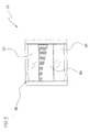
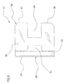
- FIGS. 2 through 8 illustrate an orthodontic bracket and positioning system 10 , which comprises a base 20 , a bracket member 30 attached to the base 20 , a vertical passage 32 and a horizontal passage 31 within the bracket, and a front slot 34 within the bracket member 30 for receiving an archwire 40 .
- At least one ligature member 50 extends through the vertical passage 32 and about the archwire 40 for securing the archwire 40 within the front slot 34 .
- the vertical passage 32 is substantially traversed with respect to the front slot 34 for allowing the ligature member 50 to extend about the archwire 40 substantially traverse to the archwire 40 .
- a gauge member 60 is utilized to properly orient the orthodontic bracket and positioning system 10 with respect to the longitudinal axis of the tooth 12 .
- the base 20 is comprised of a flat structure having a front surface 22 and a rear surface 24 .
- the rear surface 24 of the base 20 is secured to the outer surface of the tooth 12 utilizing a conventional adhesive or bonding technique.
- the base 20 may have various shapes and sizes other than illustrated within Figures 2 through 8 of the drawings.
- the base 20 is preferably comprised of a mesh structure, however a solid material may also be utilized to construct the base 20 .
- the base 20 may be comprised of various types of materials, colors and structures as can be appreciated.
- the bracket member 30 is secured to the front surface 22 of the base 20 opposite of the tooth 12 .
- the bracket member 30 may be secured to the base 20 utilizing various securing methods. Additionally, the bracket member 30 and the base 20 may be constructed from a single solid structure thereby requiring no additional attachment thereof.
- the bracket member 30 may be comprised of various types of materials, colors and transparencies.
- the bracket member 30 may also have various other shapes and designs other than that illustrated within Figures 1 through 8 of the drawings.
- a vertical passage 32 extends through a rear portion of the bracket member 30 for receiving at least one ligature member 50 .
- the vertical passage 32 preferably has a rectangular cross sectional shape, however various other shapes may be utilized such as but not limited to circular, square, oval, and triangular.
- the vertical passage 32 may have various widths, however the vertical passage 32 is preferably sufficient in size to receive at least one ligature member 50 .
- the vertical passage 32 preferably extends in a vertical manner through the rear portion of the bracket member 30 substantially traverse to the front slot 34 .
- a horizontal vertical passage 31 extends through a rear portion of the bracket member 30 substantially transverse with respect to the vertical passage 32 for receiving at least one ligature member 50 .
- the horizontal vertical passage 31 preferably has a rectangular cross sectional shape, however various other shapes may be utilized such as but not limited to circular, square, oval, and triangular.
- the horizontal vertical passage 31 may have various widths, however the horizontal vertical passage 31 is preferably sufficient in size to receive at least one archwire 40 or ligature member 50 .
- the horizontal vertical passage 31 preferably extends in a horizontal manner through the rear portion of the bracket member 30 substantially parallel to the front slot 34 .
- the bracket member 30 includes a first wall 38 and a second wall 39 extending from the base 20 in opposition to one another thereby defining the sides of the vertical passage 32 .
- the walls 38, 39 are preferably substantially parallel to one another as best shown in Figure 3 of the drawings.
- the walls 38, 39 are enclosed by a traverse wall portion as shown in Figures 3 and 8 of the drawings. As shown in Figures 3 through 5 of the drawings, the portion of the walls 38, 39 engaging the base 20 are preferably flanged outwardly thereby providing an increased surface area for securing the bracket member 30 to the base 20 without obstructing the vertical passage 32 .
- a lower extension 36 and an upper extension 37 extend forwardly from the traverse wall portion.
- the extensions 36, 37 are preferably parallel to one another as best illustrated in Figures 3 and 6 of the drawings.
- the extensions 36, 37 preferably are each comprised of a relatively broad width and a relatively narrow height thereto.
- the extensions 36, 37 preferably have a flat front portion for preventing the collection of debris and food.
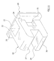
- the extensions 36, 37 preferably have beveled edges as illustrated in Figure 3 or rounded edges as illustrated in Figure 11.
- the opposing extensions 36, 37 define a front slot 34 between thereof for receiving a portion of the archwire 40 .
- the front slot 34 has a rectangular cross section, however various other cross sectional shapes may be utilized to construct the front slot 34 .
- the front slot 34 is preferably sufficient in depth and height to receive the archwire 40 as best illustrated in Figure 2 of the drawings.
- the front slot 34 is preferably substantially traverse with respect to the vertical passage 32 as shown in Figure 3 of the drawings.
- a pair of ligature members 50 are secured within the bracket member 30 and the archwire 40 .
- the ligature members 50 may be comprised of various types of materials such as but not limited to coated or non-coated metal wire.
- Each ligature member 50 has an elongate structure with opposing ends which are tied together after positioning within the vertical passage 32 and about the archwire 40 .
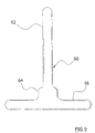
- Figure 9 illustrates a gauge member 60 which assists in the alignment of the orthodontic bracket system 10 upon the surface of the tooth 12 .
- the gauge member 60 preferably has a T-shaped structure with a shaft portion 62 and a handle portion 66 .
- a flanged portion 64 preferably extends outwardly from the shaft portion near the intersection of the handle portion 66 and the shaft portion 62. The flanged portion 64 prevents the gauge member 60 from being inserted too far into the vertical passage 32 .
- the shaft portion 62 is inserted into the vertical passage 32 of the bracket member 30 and utilized to manipulate and visually indicate the alignment with the longitudinal axis of the tooth as best illustrated in Figure 10 of the drawings. After the bracket member 30 has been properly secured to the tooth 12 , the gauge member 60 is thereafter removed from the bracket member 30 .
- the dental professional secures the bracket member 30 to a tooth 12 by applying an adhesive between the rear surface 24 of the base 20 and the tooth 12 .
- the gauge member 60 is utilized to ensure that the bracket member 30 is properly positioned.
- the adhesive is allowed to cure and the dental professional continues securing additional bracket members 30 to the teeth 12 of the patient as required.
- the dental professional then positions the archwire 40 within the front slots 34 of each of the bracket members 30 as shown in Figure 2 of the drawings.
- One or more ligature members 50 are then extended through the vertical passage 32 and bent about the side portions of the extensions 36, 37 as further shown in Figure 2 of the drawings.
- the ligature members 50 are then tightened to the desired tautness and then are secured by twisting or tying the opposing distal ends of each ligature member 50 .
- the archwire 40 is thereby retained within the front slot 34 by the ligature members 50 and allowed to slide longitudinally within the front slot 34 if required.
Landscapes
- Health & Medical Sciences (AREA)
- Oral & Maxillofacial Surgery (AREA)
- Dentistry (AREA)
- Epidemiology (AREA)
- Life Sciences & Earth Sciences (AREA)
- Animal Behavior & Ethology (AREA)
- General Health & Medical Sciences (AREA)
- Public Health (AREA)
- Veterinary Medicine (AREA)
- Dental Tools And Instruments Or Auxiliary Dental Instruments (AREA)
Abstract
Description
Claims (20)
- An orthodontic bracket system, comprising:wherein said bracket member includes a lower extension and an upper extension defining said front slot;a bracket member having a rear portion and a front portion, wherein said rear portion is attachable to a tooth;a vertical passage extending vertically through said rear portion of said bracket member;a horizontal passage extending horizontally through said rear portion of said bracket member; anda front slot extending into said front portion of said bracket member, wherein said front slot is positioned substantially horizontally within said front portion for receiving a portion of an archwire;
wherein said first wall and said second wall each have a flanged portion attached to said base. - The orthodontic bracket system of Claim 1, wherein said vertical passage is defined by a first wall, a second wall, a base extending between said first wall and said second wall, and a traverse wall portion extending between said first wall and said second wall opposite of said base.
- The orthodontic bracket system of Claim 1, wherein said vertical passage has a rectangular cross sectional shape.
- The orthodontic bracket system of Claim 1, wherein said horizontal passage is substantially transverse with respect to said vertical passage.
- The orthodontic bracket system of Claim 1, wherein said lower extension and said upper extension have beveled outer edges.
- The orthodontic bracket system of Claim 1, wherein said lower extension and said upper extension have rounded outer edges.
- The orthodontic bracket system of Claim 1, wherein said base is comprised of a mesh material.
- The orthodontic bracket system of Claim 1, wherein said lower extension and said upper extension are substantially parallel to one another.
- The orthodontic bracket system of Claim 1, wherein said front slot has a rectangular cross sectional shape.
- The orthodontic bracket system of Claim 1, wherein horizontal passage is comprised of a rectangular structure.
- An orthodontic bracket and positioning system, comprising:a bracket member having a rear portion and a front portion, wherein said rear portion is attachable to a tooth;a vertical passage extending vertically through said rear portion of said bracket member;a front slot extending into said front portion of said bracket member, wherein said front slot is positioned substantially horizontally within said front portion for receiving a portion of an archwire; anda gauge member having a T-shaped structure removably positionable within said vertical passage for aligning said bracket member with respect to a longitudinal axis of a tooth.
- The orthodontic bracket and positioning system of Claim 11, wherein said vertical passage is defined by a first wall, a second wall, a base extending between said first wall and said second wall, and a traverse wall portion extending between said first wall and said second wall opposite of said base.
- The orthodontic bracket and positioning system of Claim 11, wherein said vertical passage has a rectangular cross sectional shape.
- The orthodontic bracket and positioning system of Claim 11, wherein said horizontal passage is substantially transverse with respect to said vertical passage.
- The orthodontic bracket and positioning system of Claim 11, wherein said bracket member includes a lower extension and an upper extension defining said front slot and wherein said lower extension and said upper extension have beveled outer edges.
- The orthodontic bracket and positioning system of Claim 11, wherein said bracket member includes a lower extension and an upper extension defining said front slot and wherein said lower extension and said upper extension have rounded outer edges.
- The orthodontic bracket and positioning system of Claim 11, wherein said base is comprised of a mesh material.
- The orthodontic bracket and positioning system of Claim 11, wherein said bracket member includes a lower extension and an upper extension defining said front slot and wherein said lower extension and said upper extension are substantially parallel to one another.
- The orthodontic bracket and positioning system of Claim 11, wherein said front slot has a rectangular cross sectional shape.
- An orthodontic bracket system, comprising:wherein said bracket member includes a lower extension and an upper extension defining said front slot, wherein said lower extension and said upper extension each have a rectangular structure with a longitudinal axis parallel to said front slot;a bracket member having a rear portion and a front portion, wherein said rear portion is attachable to a tooth;a vertical passage extending vertically through said rear portion of said bracket member;a horizontal passage extending horizontally through said rear portion of said bracket member;a front slot extending into said front portion of said bracket member, wherein said front slot is positioned substantially horizontally within said front portion for receiving a portion of an archwire; andat least one ligature member securable within said vertical passage and about said archwire, wherein said ligature member is comprised of an elongate structure having opposing ends and is comprised of a flexible material;
wherein said vertical passage is defined by a first wall, a second wall, a base extending between said first wall and said second wall, and a traverse wall portion extending between said first wall and said second wall opposite of said base;
wherein said first wall and said second wall each have a flanged portion attached to said base;
wherein said vertical passage has a rectangular cross sectional shape;
wherein said base is comprised of a mesh material;
wherein said lower extension and said upper extension are substantially parallel to one another; and
wherein said front slot has a rectangular cross sectional shape.
Applications Claiming Priority (2)
| Application Number | Priority Date | Filing Date | Title |
|---|---|---|---|
| US434933 | 1995-05-04 | ||
| US10/434,933 US6902396B2 (en) | 2001-10-16 | 2003-05-09 | Orthodontic bracket and positioning system |
Publications (2)
| Publication Number | Publication Date |
|---|---|
| EP1475051A2 true EP1475051A2 (en) | 2004-11-10 |
| EP1475051A3 EP1475051A3 (en) | 2006-04-05 |
Family
ID=32990567
Family Applications (1)
| Application Number | Title | Priority Date | Filing Date |
|---|---|---|---|
| EP04386008A Withdrawn EP1475051A3 (en) | 2003-05-09 | 2004-03-12 | Orthodontic bracket and positioning system |
Country Status (2)
| Country | Link |
|---|---|
| US (1) | US6902396B2 (en) |
| EP (1) | EP1475051A3 (en) |
Cited By (1)
| Publication number | Priority date | Publication date | Assignee | Title |
|---|---|---|---|---|
| NL1032154C2 (en) * | 2006-07-12 | 2008-01-15 | Janalt Damstra | Orthodontic bracket of twin type involves method for retention of curved thread or wire in groove in bracket, with thread or wire enclosed in appropriately formed component |
Families Citing this family (4)
| Publication number | Priority date | Publication date | Assignee | Title |
|---|---|---|---|---|
| US9345558B2 (en) | 2010-09-03 | 2016-05-24 | Ormco Corporation | Self-ligating orthodontic bracket and method of making same |
| CN108464871A (en) * | 2018-04-27 | 2018-08-31 | 杭州新亚齿科材料有限公司 | A kind of transmission bracket of self-locking |
| EP4287985B1 (en) * | 2021-02-08 | 2025-06-11 | Solventum Intellectual Properties Company | Orthodontic appliance, orthodontic system |
| CN114081646B (en) * | 2021-11-24 | 2023-11-28 | 重庆医科大学附属第二医院 | Self-locking correction system beneficial to multidimensional control |
Family Cites Families (26)
| Publication number | Priority date | Publication date | Assignee | Title |
|---|---|---|---|---|
| US3320525A (en) | 1953-03-16 | 1967-05-16 | Philco Ford Corp | Impedance bridge measuring system including a self-oscillatory loop between the bridge input and output |
| US3729826A (en) | 1971-07-16 | 1973-05-01 | P Kesling | Lock ring for edgewise bracket |
| US4192070A (en) | 1978-01-16 | 1980-03-11 | Chong Ian M | Orthodontic devices |
| JPS6111037A (en) | 1984-06-28 | 1986-01-18 | 三金工業株式会社 | Dental orthodontic apparatus |
| US4559012A (en) * | 1984-12-06 | 1985-12-17 | Pletcher Erwin Carroll | Orthodontic bracket |
| US4585413A (en) | 1984-12-31 | 1986-04-29 | Wool Arthur L | Orthodontic device |
| US4626208A (en) * | 1985-08-16 | 1986-12-02 | Tp Orthodontics, Inc. | Positioning jig for edgewise bracket |
| GB2200847B (en) | 1987-01-29 | 1991-01-02 | Robert Andrew Parker | Orthodontic bracket |
| US4948367A (en) | 1988-06-17 | 1990-08-14 | Summit Orthodontic Services, Inc. | Orthodontic accessories and method of applying the same |
| US4927362A (en) | 1988-07-12 | 1990-05-22 | Unitek Corporation | Convertible buccal tube |
| US5098288A (en) | 1990-05-04 | 1992-03-24 | Tp Orthodontics, Inc. | Flexible bonding pad for an orthodontic bracket |
| GB9014341D0 (en) | 1990-06-27 | 1990-08-15 | Orthodontic Research Australia | Orthodontic bracket |
| US5322435A (en) | 1992-07-23 | 1994-06-21 | Pletcher Erwin Carroll | Orthodontic bracket |
| JPH0626814U (en) * | 1992-09-01 | 1994-04-12 | 和也 渡辺 | Orthodontic bracket |
| US5295823A (en) * | 1992-10-30 | 1994-03-22 | Ormco Corporation | Orthodontic appliances having improved bonding characteristics |
| US5439378A (en) * | 1993-04-08 | 1995-08-08 | Damon Family Limited Partnership | Orthodontic bracket assembly and method of installation |
| US5464349A (en) | 1993-11-09 | 1995-11-07 | Ormco Corporation | Orthodontic appliance providing for mesial rotation of molars |
| US5618175A (en) | 1995-02-21 | 1997-04-08 | Ormco Corporation | Plastic orthodontic bracket having rotation wings |
| BR9502793A (en) * | 1995-06-14 | 1997-09-23 | Aquino Leite Weber De | Orthodontic support |
| US5823771A (en) | 1997-05-27 | 1998-10-20 | Nord; Philip J. | Vertical straight wire orthodontic aplliance having interchangeable anchor components |
| ES2369250T3 (en) | 1997-10-24 | 2011-11-28 | Rmo, Inc. | FIXING MECHANISM FOR A TUBE AND SPIG METAL DEVICE. |
| US5971754A (en) | 1998-07-30 | 1999-10-26 | Sondhi; Anoop | Indirect bonding method and adhesive for orthodontic treatment |
| JP4444410B2 (en) * | 1999-10-08 | 2010-03-31 | トミー株式会社 | Orthodontic brackets and tools for orthodontic brackets |
| US6206690B1 (en) | 1999-10-08 | 2001-03-27 | Ormco Corporation | Orthodontic appliance and methods of installation and removal |
| US6682345B2 (en) * | 2002-03-25 | 2004-01-27 | Tp Orthodontics, Inc. | Orthodontic bracket |
| US7094053B2 (en) * | 2002-05-28 | 2006-08-22 | Ormco Corporation | Custom jig for placing orthodontic brackets and methods of making and using same |
-
2003
- 2003-05-09 US US10/434,933 patent/US6902396B2/en not_active Expired - Fee Related
-
2004
- 2004-03-12 EP EP04386008A patent/EP1475051A3/en not_active Withdrawn
Cited By (1)
| Publication number | Priority date | Publication date | Assignee | Title |
|---|---|---|---|---|
| NL1032154C2 (en) * | 2006-07-12 | 2008-01-15 | Janalt Damstra | Orthodontic bracket of twin type involves method for retention of curved thread or wire in groove in bracket, with thread or wire enclosed in appropriately formed component |
Also Published As
| Publication number | Publication date |
|---|---|
| EP1475051A3 (en) | 2006-04-05 |
| US20030194674A1 (en) | 2003-10-16 |
| US6902396B2 (en) | 2005-06-07 |
Similar Documents
| Publication | Publication Date | Title |
|---|---|---|
| US5123838A (en) | Orthodontic bracket | |
| US5356288A (en) | Dual orthodontic bracket | |
| KR102511765B1 (en) | Orthodontic system with variable size archwire slots | |
| DE69228472T2 (en) | IMPROVED EDGE ORTHODONTIC CLAMP | |
| US4386908A (en) | Lingual orthodontic appliance system for the mandibular arch | |
| CH667798A5 (en) | ORTHODAEDIC EDGEWISE THERAPY DEVICE. | |
| US4799882A (en) | Edgewise bracket | |
| US8251697B2 (en) | Reduced-friction buccal tube and method of use | |
| US5746592A (en) | Edgewise orthodontic bracket with tie wing relief for enhancing ligature removal | |
| US4669981A (en) | Lingual orthodontic appliance system | |
| US5320525A (en) | Orthodontic bracket | |
| US20230058890A1 (en) | Direct bonding guide systems | |
| CA1233682A (en) | Edgewise bracket | |
| US6478579B1 (en) | Orthodontic twin bracket with archwire floor and side wall relief | |
| US5226814A (en) | Orthodonic bracket | |
| US20160270885A1 (en) | Dental wire supporter for orthodontic treatment and orthodontic device having the same | |
| JPH02257946A (en) | Convertible buccal tube | |
| DE112007000142T5 (en) | Orthodontic hybrid archwire | |
| US6902396B2 (en) | Orthodontic bracket and positioning system | |
| US6592367B2 (en) | Orthodontic bracket system | |
| US6074207A (en) | Orthodontic device for repositioning the molars | |
| US5302116A (en) | Orthodontic bracket | |
| US7549860B2 (en) | Hand instrument for detaching orthodontic brackets from teeth | |
| US3787976A (en) | Calibrated bracket securing means | |
| EP3328312B1 (en) | An orthodontic anchorage device |
Legal Events
| Date | Code | Title | Description |
|---|---|---|---|
| PUAI | Public reference made under article 153(3) epc to a published international application that has entered the european phase |
Free format text: ORIGINAL CODE: 0009012 |
|
| AK | Designated contracting states |
Kind code of ref document: A2 Designated state(s): AT BE BG CH CY CZ DE DK EE ES FI FR GB GR HU IE IT LI LU MC NL PL PT RO SE SI SK TR |
|
| AX | Request for extension of the european patent |
Extension state: AL HR LT LV MK |
|
| PUAL | Search report despatched |
Free format text: ORIGINAL CODE: 0009013 |
|
| AK | Designated contracting states |
Kind code of ref document: A3 Designated state(s): AT BE BG CH CY CZ DE DK EE ES FI FR GB GR HU IE IT LI LU MC NL PL PT RO SE SI SK TR |
|
| AX | Request for extension of the european patent |
Extension state: AL LT LV MK |
|
| 17P | Request for examination filed |
Effective date: 20060918 |
|
| AKX | Designation fees paid |
Designated state(s): AT BE BG CH CY CZ DE DK EE ES FI FR GB GR HU IE IT LI LU MC NL PL PT RO SE SI SK TR |
|
| STAA | Information on the status of an ep patent application or granted ep patent |
Free format text: STATUS: THE APPLICATION IS DEEMED TO BE WITHDRAWN |
|
| 18D | Application deemed to be withdrawn |
Effective date: 20101001 |