EP1474980A2 - Bread maker - Google Patents
Bread maker Download PDFInfo
- Publication number
- EP1474980A2 EP1474980A2 EP03258139A EP03258139A EP1474980A2 EP 1474980 A2 EP1474980 A2 EP 1474980A2 EP 03258139 A EP03258139 A EP 03258139A EP 03258139 A EP03258139 A EP 03258139A EP 1474980 A2 EP1474980 A2 EP 1474980A2
- Authority
- EP
- European Patent Office
- Prior art keywords
- tray
- stationary
- slit
- pair
- bread maker
- Prior art date
- Legal status (The legal status is an assumption and is not a legal conclusion. Google has not performed a legal analysis and makes no representation as to the accuracy of the status listed.)
- Granted
Links
Images



Classifications
-
- A—HUMAN NECESSITIES
- A21—BAKING; EDIBLE DOUGHS
- A21B—BAKERS' OVENS; MACHINES OR EQUIPMENT FOR BAKING
- A21B7/00—Baking plants
- A21B7/005—Baking plants in combination with mixing or kneading devices
-
- A—HUMAN NECESSITIES
- A21—BAKING; EDIBLE DOUGHS
- A21B—BAKERS' OVENS; MACHINES OR EQUIPMENT FOR BAKING
- A21B1/00—Bakers' ovens
Definitions
- the present invention relates to bread makers, and more particularly, though not exclusively to bread makers in which dough in a mixing bag can be uniformly kneaded during a kneading process.
- bread is made by using a bread maker which automatically performs multiple steps such as kneading, leavening and baking of raw materials for bread.
- the bread maker disclosed in Korean Patent Publication No.2001-0032188 includes a housing forming an external appearance of a bread maker; a door provided in the housing; and an LCD display part provided in a front side of housing.
- Upper and lower rollers are rotatably disposed in parallel in the upper and lower parts of the housing to wind opposite ends of a mixing bag.
- a pair of upper members are placed between the upper and lower rollers to prevent the raw materials kneaded in the mixing bag from being moved to the upper roller.
- a baking tray is provided between the pair of upper members and the lower roller which can be slid out of the oven compartment and contains kneaded materials therein.
- the baking tray is box-shaped having a top opening by combining a stationary part and a movable part symmetrical to each other.
- a slit is formed along the line where the movable part meets the stationary part and extends from a sidewall to the bottom, wherein pivot means of the movable part is combined with pivot holders.
- the raw materials contained in the mixing bag are reciprocated up and down by the upper and lower rollers during a kneading process, thereby being kneaded between the pair of upper members and the baking tray. After completing the kneading process, the mixing bag is removed and dough contained in the baking tray is baked.
- the mixing bag is reciprocated up and down through the slit of the baking tray during a kneading process.
- the pair of upper members prevents the dough in the mixing bag from being moved up toward the upper roller.
- the mixing bag moves down, the dough in the mixing bag cannot pass through the narrow slit of the baking tray, so that the dough can be repetitively kneaded.
- it is essential to keep the width of the slit constant in spite of repetitive usage.
- a means for adjusting the width of the slit may be required so as to keep the width of the slit constant.
- a bread maker comprising a main body forming an oven compartment; an upper kneading drum and a lower kneading drum which are spaced apart from each other in an upper part and a lower part of the oven compartment and hold opposite ends of a mixing bag, respectively; a baking tray having a stationary tray member and a movable tray member which are disposed between the upper and lower kneading drums facing each other and forming a slit to pass the mixing bag through, wherein the movable tray member is formed with a plurality of combining projections on opposite sidewalls thereof; and a pair of tray holder members which supports the stationary tray member and is formed with a plurality of guide grooves to accommodate the plurality of combining projections for moveably supporting the movable tray member, being combined with opposite ends of the pair of tray holder members, wherein a screw hole communicated with the plurality of guide grooves is formed at one end of each of the tray holder members and an adjusting
- each of the tray holder members is formed with a first guide groove, a second guide groove and a screw hole which is communicated with the second guide groove toward the transverse direction of the slit.
- the bread maker further comprises a pair of dough profile parts which is projected facing each other in the slit and contacts with the mixing bag.
- the adjusting member is an adjusting bolt screw-engaged with the screw hole of the tray holder member.
- a bread maker according to a preferred embodiment of the present invention comprises: a main body 1 provided with an oven compartment 10; a door 3 to rotatably open and close a front opening of the oven compartment 10; and an operation display panel to show an operation state of the main body 1.
- Upper and lower kneading drums 11 and 12 rotatably disposed in the upper and lower parts of the oven compartment 10 are placed in parallel to wind opposite ends of a mixing bag (not shown) filled with raw materials for bread in clockwise and counterclockwise directions.
- a pair of dough-blocking members 13 are placed between the upper and lower kneading drums 11 and 12 to prevent the raw materials kneaded in the mixing bag from being moved to the upper kneading drum 11.
- a baking tray assembly 20 is provided between the upper and lower kneading drums 11 and 12 in the lower part of the oven compartment 10.
- the baking tray assembly 20 may be slid out from the oven compartment 10 and contains kneaded materials for bread therein.
- the baking tray assembly 20 comprises a baking tray 30 having stationary and movable tray members 31 and 33 respectively, both of L-shaped sections symmetrical to each other; and a pair of tray holder members 40 connected with opposite ends of the stationary and movable tray members 31 and 33, respectively.
- Stationary projections 32 securely combined with the pair of tray holder members 40 are projected from the lower surface of the opposite sidewalls of the stationary tray member 31.
- Combining projections 34 movably combined with the pair of tray holder members 40 are projected from the lower surface of the opposite sidewalls of the movable tray member 33.
- the pair of tray holder members 40 is slidingly combined with guide members 14 which are mounted on opposite inner sidewalls of the oven compartment 10.
- the stationary projections 32 of the stationary tray member 31 are inserted into the stationary projections accommodating parts 41 which are grooved into the tray holder member 40.
- the combining projections 34 of the movable tray member 33 are movably inserted into guide grooves 42 formed in the tray holder member 40.
- the guide grooves 42 form a pair provided in each of the tray holder members 40 and comprise a first guide groove 42a positioned adjacent to the stationary tray member 31 and a second guide groove 42b positioned adjacent to the first guide groove 42a.
- the stationary tray member 31 When the stationary projections 32 of the stationary tray member 31 are inserted in the stationary projections accommodating parts 41 of the tray holder member 40, the stationary tray member 31 is securely mounted on the tray holder member 40. Similarly, when the combining projections 34 of the pivotably movable tray member 33 are movably inserted in the guide grooves 42 of the tray holder member 40, the movable tray member 33 is movably mounted on the tray holder member 40.
- the baking tray 30 of a box shape having a top opening for containing the raw materials for bread is formed.
- a slit 21 is formed along the line where the stationary and movable tray members 31 and 33 are met.
- a pair of dough profile parts 50 are provided in the slit 21. The dough profile parts are projected facing each other and contacting with each other when the mixing bag is introduced between the slit 21.
- the bread maker further comprises an adjusting means which adjusts the width of the slit 21 so as to keep the width constant when the mixing bag is reciprocated up and down through the slit 21.
- the adjusting means comprises a screw hole 60 formed at the front end of the tray holder member 40 along the transverse direction of the slit 21 and communicated with the second guide groove 42b; and an adjusting bolt 61 as an adjusting member which is screw-engaged with the screw hole 60 and moves the movable tray member 33 toward the transverse direction of the slit 21, so that the width of the slit 21 can be adjusted.
- the threaded part of the adjusting bolt 61 is moved forward into the second guide groove 42b along the transverse direction of the slit 21.
- the combining projection 34 in the second guide groove 42b is moved forward toward the transverse direction of the slit 21 because when the adjusting bolt 61 moves forward, it pushes the combining projection 34 forward.
- the movable tray member 33 formed with the combining projection 34 is moved slightly forward, so that the width of the slit 21 between the stationary and movable tray members 31 and 33 can be adjusted.
- One end of the mixing bag contained inside of the oven compartment 10 is wound by the upper kneading drum 11.
- the other end of the mixing bag passes through the pair of dough-blocking members 13 and the slit 21 formed at the bottom of the baking tray 30 and then the mixing bag is wound by the lower kneading drum 12.
- the mixing bag filled with the raw materials for bread is reciprocated up and down by the upper and lower kneading drums 11 and 12 during a kneading process, so that the raw materials for bread are kneaded between the pair of dough-blocking members 13 and the baking tray 30.
- the mixing bag is released from the upper kneading drum 11 because only the lower kneading drum 12 is rotated.
- the mixing bag passes through the pair of dough-blocking members 13 and finally the slit 21 formed at the bottom of the baking tray 30.
- the mixing bag passes through the slit 21 of the baking tray 30, the kneaded dough contained in the mixing bag cannot pass the slit 21 of the baking tray 30, therefore, the kneaded dough is separated from the mixing bag and contained in the baking tray 30.
- the mixing bag can pass through the slit 21 of the baking tray 30 and is wound by the lower kneading drum 12. Thereafter, the kneaded dough contained in the baking tray 30 is baked by the baking heater 16.
- the width of the slit 21 can be adjusted by the adjusting bolt 61, which make the raw materials contained in the mixing bag uniformly kneaded between the pair of dough-blocking members 13 and the baking tray 30.
- the width of the slit 21 can be adjusted by rotating each of the adjusting bolts 61 combined with the pair of tray holder members 40.
- the bread maker further comprises an adjusting means having a screw hole 60 and an adjusting bolt 61.
- the adjusting bolt 61 screw-engaged with the screw hole 60 is rotated for adjusting the width of the slit 21, the threaded part of the adjusting bolt 61 is moved forward into the second guide groove 42b along the transverse direction of the slit 21.
- the combining projection 34 in the second guide groove 42b is moved forward toward the transverse direction of the slit 21 because when the adjusting bolt 61 moves forward, it pushes the combining projection 34 forward.
- the movable tray member 33 formed with the combining projection 34 is moved slightly forward, so that the width of the slit 21 between the stationary and movable tray members 31 and 33 becomes narrower.
- the adjusting bolt 61 is rotated in the reverse direction, the adjusting bolt 61 contacted with the combining projection 34 in the second guide groove 42b is moved backward.
- the movable tray member 33 is moved backward apart from the stationary tray member 31, so that the width of the slit becomes broader.
- the width of the slit 21 may be adjusted so as to keep the width of the slit 21 constant, which is required for the uniform kneading of the dough in the mixing bag.
Landscapes
- Life Sciences & Earth Sciences (AREA)
- Engineering & Computer Science (AREA)
- Food Science & Technology (AREA)
- Baking, Grill, Roasting (AREA)
- Food-Manufacturing Devices (AREA)
- Bakery Products And Manufacturing Methods Therefor (AREA)
- Manufacturing And Processing Devices For Dough (AREA)
Abstract
Description
- The present invention relates to bread makers, and more particularly, though not exclusively to bread makers in which dough in a mixing bag can be uniformly kneaded during a kneading process.
- Generally, bread is made by using a bread maker which automatically performs multiple steps such as kneading, leavening and baking of raw materials for bread.
- For example, the bread maker disclosed in Korean Patent Publication No.2001-0032188 includes a housing forming an external appearance of a bread maker; a door provided in the housing; and an LCD display part provided in a front side of housing.
- Upper and lower rollers are rotatably disposed in parallel in the upper and lower parts of the housing to wind opposite ends of a mixing bag. A pair of upper members are placed between the upper and lower rollers to prevent the raw materials kneaded in the mixing bag from being moved to the upper roller.
- A baking tray is provided between the pair of upper members and the lower roller which can be slid out of the oven compartment and contains kneaded materials therein.
- The baking tray is box-shaped having a top opening by combining a stationary part and a movable part symmetrical to each other. A slit is formed along the line where the movable part meets the stationary part and extends from a sidewall to the bottom, wherein pivot means of the movable part is combined with pivot holders.
- The raw materials contained in the mixing bag are reciprocated up and down by the upper and lower rollers during a kneading process, thereby being kneaded between the pair of upper members and the baking tray. After completing the kneading process, the mixing bag is removed and dough contained in the baking tray is baked.
- In a conventional bread maker, the mixing bag is reciprocated up and down through the slit of the baking tray during a kneading process. When the mixing bag moves up, the pair of upper members prevents the dough in the mixing bag from being moved up toward the upper roller. When the mixing bag moves down, the dough in the mixing bag cannot pass through the narrow slit of the baking tray, so that the dough can be repetitively kneaded. Thus, it is essential to keep the width of the slit constant in spite of repetitive usage. Hence, to obtain well-kneaded uniform dough from materials in the mixing bag, a means for adjusting the width of the slit may be required so as to keep the width of the slit constant.
- Accordingly, it is an aim of preferred embodiments of the present invention to provide a bread maker in which dough in a mixing bag can be uniformly kneaded during the kneading process.
- According to the present invention there is provided a bread maker comprising a main body forming an oven compartment; an upper kneading drum and a lower kneading drum which are spaced apart from each other in an upper part and a lower part of the oven compartment and hold opposite ends of a mixing bag, respectively; a baking tray having a stationary tray member and a movable tray member which are disposed between the upper and lower kneading drums facing each other and forming a slit to pass the mixing bag through, wherein the movable tray member is formed with a plurality of combining projections on opposite sidewalls thereof; and a pair of tray holder members which supports the stationary tray member and is formed with a plurality of guide grooves to accommodate the plurality of combining projections for moveably supporting the movable tray member, being combined with opposite ends of the pair of tray holder members, wherein a screw hole communicated with the plurality of guide grooves is formed at one end of each of the tray holder members and an adjusting member moving the movable tray member is connected with the screw hole .
- Suitably, each of the tray holder members is formed with a first guide groove, a second guide groove and a screw hole which is communicated with the second guide groove toward the transverse direction of the slit.
- Suitably, the bread maker further comprises a pair of dough profile parts which is projected facing each other in the slit and contacts with the mixing bag.
- Suitably, the adjusting member is an adjusting bolt screw-engaged with the screw hole of the tray holder member.
- Further features of the present invention are set out in the appended claims.
- The present invention will become apparent and more readily appreciated from the following description of an embodiment, by way of example only, taken in conjunction with the accompanying drawings of which:
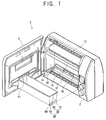
- FIG. 1 is a perspective view illustrating a baking tray assembly of a bread maker of the present invention;
- FIG. 2 is a combined perspective view of the baking tray assembly of FIG. 1;
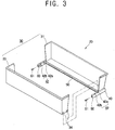
- FIG. 3 is an exploded perspective view of the baking tray assembly of FIG. 2;
- FIGS. 4 and 5 are sectional views illustrating how a movable tray member moves to adjust the width of the slit, taken along line IV-IV in FIG. 2.
-
- Reference will now be made in detail to an embodiment of the present invention, an example of which is illustrated in the accompanying drawings, wherein like reference numerals refer to like elements throughout. The embodiment is described below in order to explain the present invention by referring to the figures.
- In FIGS. 1-3, a bread maker according to a preferred embodiment of the present invention comprises: a main body 1 provided with an
oven compartment 10; adoor 3 to rotatably open and close a front opening of theoven compartment 10; and an operation display panel to show an operation state of the main body 1. - Upper and
lower kneading drums oven compartment 10 are placed in parallel to wind opposite ends of a mixing bag (not shown) filled with raw materials for bread in clockwise and counterclockwise directions. A pair of dough-blockingmembers 13 are placed between the upper andlower kneading drums drum 11. - A
baking tray assembly 20 is provided between the upper andlower kneading drums oven compartment 10. Thebaking tray assembly 20 may be slid out from theoven compartment 10 and contains kneaded materials for bread therein. - The
baking tray assembly 20 comprises abaking tray 30 having stationary andmovable tray members tray holder members 40 connected with opposite ends of the stationary andmovable tray members -
Stationary projections 32 securely combined with the pair oftray holder members 40 are projected from the lower surface of the opposite sidewalls of thestationary tray member 31. Combiningprojections 34 movably combined with the pair oftray holder members 40 are projected from the lower surface of the opposite sidewalls of themovable tray member 33. - The pair of
tray holder members 40 is slidingly combined withguide members 14 which are mounted on opposite inner sidewalls of theoven compartment 10. Thestationary projections 32 of thestationary tray member 31 are inserted into the stationaryprojections accommodating parts 41 which are grooved into thetray holder member 40. The combiningprojections 34 of themovable tray member 33 are movably inserted intoguide grooves 42 formed in thetray holder member 40. - The guide grooves 42 form a pair provided in each of the
tray holder members 40 and comprise afirst guide groove 42a positioned adjacent to thestationary tray member 31 and asecond guide groove 42b positioned adjacent to thefirst guide groove 42a. - When the
stationary projections 32 of thestationary tray member 31 are inserted in the stationaryprojections accommodating parts 41 of thetray holder member 40, thestationary tray member 31 is securely mounted on thetray holder member 40. Similarly, when the combiningprojections 34 of the pivotablymovable tray member 33 are movably inserted in theguide grooves 42 of thetray holder member 40, themovable tray member 33 is movably mounted on thetray holder member 40. - When the stationary and
movable tray members tray holder member 40 facing each other, thebaking tray 30 of a box shape having a top opening for containing the raw materials for bread is formed. Aslit 21 is formed along the line where the stationary andmovable tray members dough profile parts 50 are provided in theslit 21. The dough profile parts are projected facing each other and contacting with each other when the mixing bag is introduced between theslit 21. - The bread maker further comprises an adjusting means which adjusts the width of the
slit 21 so as to keep the width constant when the mixing bag is reciprocated up and down through theslit 21. - The adjusting means comprises a
screw hole 60 formed at the front end of thetray holder member 40 along the transverse direction of theslit 21 and communicated with thesecond guide groove 42b; and an adjustingbolt 61 as an adjusting member which is screw-engaged with thescrew hole 60 and moves themovable tray member 33 toward the transverse direction of theslit 21, so that the width of theslit 21 can be adjusted. - When the adjusting
bolt 61 screw-engaged with thescrew hole 60 is rotated for adjusting the width of the slit, the threaded part of the adjustingbolt 61 is moved forward into thesecond guide groove 42b along the transverse direction of theslit 21. Then, the combiningprojection 34 in thesecond guide groove 42b is moved forward toward the transverse direction of theslit 21 because when the adjustingbolt 61 moves forward, it pushes the combiningprojection 34 forward. Accordingly, themovable tray member 33 formed with the combiningprojection 34 is moved slightly forward, so that the width of theslit 21 between the stationary andmovable tray members - One end of the mixing bag contained inside of the
oven compartment 10 is wound by the upper kneadingdrum 11. - Then, the other end of the mixing bag passes through the pair of dough-blocking
members 13 and theslit 21 formed at the bottom of thebaking tray 30 and then the mixing bag is wound by the lower kneadingdrum 12. The mixing bag filled with the raw materials for bread is reciprocated up and down by the upper andlower kneading drums members 13 and thebaking tray 30. After completing the kneading process, the mixing bag is released from the upper kneadingdrum 11 because only thelower kneading drum 12 is rotated. Then, the mixing bag passes through the pair of dough-blockingmembers 13 and finally theslit 21 formed at the bottom of thebaking tray 30. When the mixing bag passes through theslit 21 of thebaking tray 30, the kneaded dough contained in the mixing bag cannot pass theslit 21 of thebaking tray 30, therefore, the kneaded dough is separated from the mixing bag and contained in thebaking tray 30. However, the mixing bag can pass through theslit 21 of thebaking tray 30 and is wound by the lower kneadingdrum 12. Thereafter, the kneaded dough contained in thebaking tray 30 is baked by thebaking heater 16. - In the bread maker of this embodiment of the present invention, the width of the
slit 21 can be adjusted by the adjustingbolt 61, which make the raw materials contained in the mixing bag uniformly kneaded between the pair of dough-blockingmembers 13 and thebaking tray 30. - When the width of the
slit 21 is broader or narrower than the predetermined width which should be kept during the kneading process, the width of theslit 21 can be adjusted by rotating each of the adjustingbolts 61 combined with the pair oftray holder members 40. - As shown in FIGS. 3-5, the bread maker further comprises an adjusting means having a
screw hole 60 and an adjustingbolt 61. When the adjustingbolt 61 screw-engaged with thescrew hole 60 is rotated for adjusting the width of theslit 21, the threaded part of the adjustingbolt 61 is moved forward into thesecond guide groove 42b along the transverse direction of theslit 21. Then, also the combiningprojection 34 in thesecond guide groove 42b is moved forward toward the transverse direction of theslit 21 because when the adjustingbolt 61 moves forward, it pushes the combiningprojection 34 forward. Accordingly, themovable tray member 33 formed with the combiningprojection 34 is moved slightly forward, so that the width of theslit 21 between the stationary andmovable tray members bolt 61 is rotated in the reverse direction, the adjustingbolt 61 contacted with the combiningprojection 34 in thesecond guide groove 42b is moved backward. Thus, themovable tray member 33 is moved backward apart from thestationary tray member 31, so that the width of the slit becomes broader. The width of theslit 21 may be adjusted so as to keep the width of theslit 21 constant, which is required for the uniform kneading of the dough in the mixing bag. - Although a few embodiments of the present invention have been shown and described, it would be appreciated by those skilled in the art that changes may be made in these embodiments without departing from the principles and spirit of the invention, the scope of which is defined in the claims and their equivalents.
- Attention is directed to all papers and documents which are filed concurrently with or previous to this specification in connection with this application and which are open to public inspection with this specification, and the contents of all such papers and documents are incorporated herein by reference.
- All of the features disclosed in this specification (including any accompanying claims, abstract and drawings), and/or all of the steps of any method or process so disclosed, may be combined in any combination, except combinations where at least some of such features and/or steps are mutually exclusive.
- Each feature disclosed in this specification (including any accompanying claims, abstract and drawings) may be replaced by alternative features serving the same, equivalent or similar purpose, unless expressly stated otherwise. Thus, unless expressly stated otherwise, each feature disclosed is one example only of a generic series of equivalent or similar features.
- The invention is not restricted to the details of the foregoing embodiment(s). The invention extends to any novel one, or any novel combination, of the features disclosed in this specification (including any accompanying claims, abstract and drawings), or to any novel one, or any novel combination, of the steps of any method or process so disclosed.
Claims (8)
- A bread maker comprising:wherein a screw hole (60) communicated with the plurality of guide grooves (42) is formed at one end of each of the tray holder members (40) and an adjusting member (61) moving the movable tray member (33) is connected with the screw hole (60).a main body (1) forming an oven compartment (10);an upper kneading drum (11) and a lower kneading drum (12) which are spaced apart from each other in an upper part and a lower part of the oven compartment (10) and hold opposite ends of a mixing bag, respectively;a baking tray (30) having a stationary tray member (31) and a movable tray member (33) which are disposed between the upper (11) and lower (12) kneading drums facing each other and forming a slit (21) to pass the mixing bag through, wherein the movable tray member (33) is formed with a plurality of combining projections (34) on opposite sidewalls thereof; anda pair of tray holder members (40) which supports the stationary tray member (31) and is formed with a plurality of guide grooves (42) to accommodate the plurality of combining projections for movably supporting the movable tray member (33), being combined with opposite ends of the pair of tray holder members (40),
- The bread maker of claim 1, wherein each of the tray holder members (40) is formed with a first guide groove (42a) and a second guide groove (42b) and the screw hole (60) is communicated with the second guide groove (42b) toward the transverse direction of the slit (21).
- The bread maker of claim 2, further comprising:a pair of dough profile parts (50) facing each other in the slit (21) and contacting with the mixing bag.
- The bread maker of any preceding claim, wherein the adjusting member (61) is an adjusting bolt (61) screw-engaged with the screw hole (60).
- The bread maker of any preceding claim, wherein the stationary tray member (31) and the movable tray member (33) are L-shaped sections symmetrical to each other.
- The bread maker of claim 2, wherein each of the tray holder members (40) are slidingly combined with a plurality of guide members which are mounted on the inner side walls of the oven compartment (10).
- The bread maker of any preceding claim, wherein the stationary tray member (31) comprises:a plurality of stationary projections (32) projected from a lower surface of the opposite sidewalls of the stationary tray member and the plurality of stationary projections are securely combined with the pair of tray holder members.
- The bread maker of claim 7, wherein the plurality of stationary projections (32) are inserted into a plurality of stationary projections accommodating parts (41) of the pair of tray holder members (40).
Applications Claiming Priority (2)
| Application Number | Priority Date | Filing Date | Title |
|---|---|---|---|
| KR2003029089 | 2003-05-07 | ||
| KR1020030029089A KR20040096217A (en) | 2003-05-07 | 2003-05-07 | Oven for baking bread |
Publications (3)
| Publication Number | Publication Date |
|---|---|
| EP1474980A2 true EP1474980A2 (en) | 2004-11-10 |
| EP1474980A3 EP1474980A3 (en) | 2005-09-14 |
| EP1474980B1 EP1474980B1 (en) | 2007-02-28 |
Family
ID=32985978
Family Applications (1)
| Application Number | Title | Priority Date | Filing Date |
|---|---|---|---|
| EP03258139A Expired - Lifetime EP1474980B1 (en) | 2003-05-07 | 2003-12-22 | Bread maker |
Country Status (6)
| Country | Link |
|---|---|
| US (1) | US20040221740A1 (en) |
| EP (1) | EP1474980B1 (en) |
| JP (1) | JP3759741B2 (en) |
| KR (1) | KR20040096217A (en) |
| CN (1) | CN1276715C (en) |
| DE (1) | DE60312129T2 (en) |
Families Citing this family (1)
| Publication number | Priority date | Publication date | Assignee | Title |
|---|---|---|---|---|
| JP7152100B2 (en) * | 2018-03-16 | 2022-10-12 | ミツミ電機株式会社 | Sensing system, sensing method, and non-transitory computer readable medium |
Citations (1)
| Publication number | Priority date | Publication date | Assignee | Title |
|---|---|---|---|---|
| KR0132188B1 (en) | 1994-05-28 | 1998-04-17 | 김은영 | Process for the preparation of pyridobenzoxazine carboxylic acid derivatives |
Family Cites Families (6)
| Publication number | Priority date | Publication date | Assignee | Title |
|---|---|---|---|---|
| TW391867B (en) * | 1997-11-17 | 2000-06-01 | Heden Team Ag | Automatic baking apparatus and mixbag thereof |
| KR100471071B1 (en) * | 2002-07-19 | 2005-03-10 | 삼성전자주식회사 | Automatic Baking Apparatus |
| KR100471073B1 (en) * | 2002-07-19 | 2005-03-10 | 삼성전자주식회사 | Oven for baking bread |
| KR100471072B1 (en) * | 2002-07-20 | 2005-03-10 | 삼성전자주식회사 | baking machine |
| KR100456587B1 (en) * | 2002-07-20 | 2004-11-10 | 삼성전자주식회사 | Baking machine |
| KR100473061B1 (en) * | 2002-09-14 | 2005-03-10 | 삼성전자주식회사 | Baking Apparatus |
-
2003
- 2003-05-07 KR KR1020030029089A patent/KR20040096217A/en not_active Withdrawn
- 2003-12-22 EP EP03258139A patent/EP1474980B1/en not_active Expired - Lifetime
- 2003-12-22 DE DE60312129T patent/DE60312129T2/en not_active Expired - Lifetime
-
2004
- 2004-02-10 CN CNB2004100039421A patent/CN1276715C/en not_active Expired - Fee Related
- 2004-03-24 US US10/807,263 patent/US20040221740A1/en not_active Abandoned
- 2004-03-30 JP JP2004101452A patent/JP3759741B2/en not_active Expired - Fee Related
Patent Citations (1)
| Publication number | Priority date | Publication date | Assignee | Title |
|---|---|---|---|---|
| KR0132188B1 (en) | 1994-05-28 | 1998-04-17 | 김은영 | Process for the preparation of pyridobenzoxazine carboxylic acid derivatives |
Also Published As
| Publication number | Publication date |
|---|---|
| US20040221740A1 (en) | 2004-11-11 |
| DE60312129T2 (en) | 2007-11-22 |
| EP1474980A3 (en) | 2005-09-14 |
| JP3759741B2 (en) | 2006-03-29 |
| CN1276715C (en) | 2006-09-27 |
| KR20040096217A (en) | 2004-11-16 |
| DE60312129D1 (en) | 2007-04-12 |
| CN1550144A (en) | 2004-12-01 |
| EP1474980B1 (en) | 2007-02-28 |
| JP2004329904A (en) | 2004-11-25 |
Similar Documents
| Publication | Publication Date | Title |
|---|---|---|
| EP1474980B1 (en) | Bread maker | |
| KR100471073B1 (en) | Oven for baking bread | |
| EP1474982B1 (en) | A bread maker | |
| US6729227B2 (en) | Bread maker | |
| EP1475020B1 (en) | Bread maker | |
| EP1474983A1 (en) | Improvements in and relating to bread makers | |
| EP1382253A1 (en) | Improvements in and relating to bread makers | |
| EP1474981B1 (en) | Improvements in and relating to bread makers | |
| EP1475019B1 (en) | Bread maker | |
| EP1474979B1 (en) | Bread maker | |
| KR100456586B1 (en) | Baking machine | |
| EP1474987B1 (en) | Bread maker | |
| KR200195438Y1 (en) | A manufacturing machine of pizza bread | |
| JPH09206238A (en) | Toilet paper holder | |
| EP1474978A1 (en) | Bread maker | |
| KR20040096094A (en) | Baking machine |
Legal Events
| Date | Code | Title | Description |
|---|---|---|---|
| PUAI | Public reference made under article 153(3) epc to a published international application that has entered the european phase |
Free format text: ORIGINAL CODE: 0009012 |
|
| 17P | Request for examination filed |
Effective date: 20040112 |
|
| AK | Designated contracting states |
Kind code of ref document: A2 Designated state(s): AT BE BG CH CY CZ DE DK EE ES FI FR GB GR HU IE IT LI LU MC NL PT RO SE SI SK TR |
|
| AX | Request for extension of the european patent |
Extension state: AL LT LV MK |
|
| PUAL | Search report despatched |
Free format text: ORIGINAL CODE: 0009013 |
|
| AK | Designated contracting states |
Kind code of ref document: A3 Designated state(s): AT BE BG CH CY CZ DE DK EE ES FI FR GB GR HU IE IT LI LU MC NL PT RO SE SI SK TR |
|
| AX | Request for extension of the european patent |
Extension state: AL LT LV MK |
|
| AKX | Designation fees paid |
Designated state(s): DE FR GB SE |
|
| GRAP | Despatch of communication of intention to grant a patent |
Free format text: ORIGINAL CODE: EPIDOSNIGR1 |
|
| GRAS | Grant fee paid |
Free format text: ORIGINAL CODE: EPIDOSNIGR3 |
|
| GRAA | (expected) grant |
Free format text: ORIGINAL CODE: 0009210 |
|
| AK | Designated contracting states |
Kind code of ref document: B1 Designated state(s): DE FR GB SE |
|
| REG | Reference to a national code |
Ref country code: GB Ref legal event code: FG4D |
|
| REF | Corresponds to: |
Ref document number: 60312129 Country of ref document: DE Date of ref document: 20070412 Kind code of ref document: P |
|
| REG | Reference to a national code |
Ref country code: SE Ref legal event code: TRGR |
|
| PLBE | No opposition filed within time limit |
Free format text: ORIGINAL CODE: 0009261 |
|
| STAA | Information on the status of an ep patent application or granted ep patent |
Free format text: STATUS: NO OPPOSITION FILED WITHIN TIME LIMIT |
|
| 26N | No opposition filed |
Effective date: 20071129 |
|
| PGFP | Annual fee paid to national office [announced via postgrant information from national office to epo] |
Ref country code: GB Payment date: 20101222 Year of fee payment: 8 |
|
| PGFP | Annual fee paid to national office [announced via postgrant information from national office to epo] |
Ref country code: DE Payment date: 20101215 Year of fee payment: 8 |
|
| PGFP | Annual fee paid to national office [announced via postgrant information from national office to epo] |
Ref country code: SE Payment date: 20111118 Year of fee payment: 9 Ref country code: FR Payment date: 20111201 Year of fee payment: 9 |
|
| PG25 | Lapsed in a contracting state [announced via postgrant information from national office to epo] |
Ref country code: SE Free format text: LAPSE BECAUSE OF NON-PAYMENT OF DUE FEES Effective date: 20121223 |
|
| GBPC | Gb: european patent ceased through non-payment of renewal fee |
Effective date: 20121222 |
|
| REG | Reference to a national code |
Ref country code: FR Ref legal event code: ST Effective date: 20130830 |
|
| REG | Reference to a national code |
Ref country code: DE Ref legal event code: R119 Ref document number: 60312129 Country of ref document: DE Effective date: 20130702 |
|
| PG25 | Lapsed in a contracting state [announced via postgrant information from national office to epo] |
Ref country code: DE Free format text: LAPSE BECAUSE OF NON-PAYMENT OF DUE FEES Effective date: 20130702 |
|
| PG25 | Lapsed in a contracting state [announced via postgrant information from national office to epo] |
Ref country code: GB Free format text: LAPSE BECAUSE OF NON-PAYMENT OF DUE FEES Effective date: 20121222 Ref country code: FR Free format text: LAPSE BECAUSE OF NON-PAYMENT OF DUE FEES Effective date: 20130102 |