EP1474976A1 - Bread maker - Google Patents
Bread maker Download PDFInfo
- Publication number
- EP1474976A1 EP1474976A1 EP03257913A EP03257913A EP1474976A1 EP 1474976 A1 EP1474976 A1 EP 1474976A1 EP 03257913 A EP03257913 A EP 03257913A EP 03257913 A EP03257913 A EP 03257913A EP 1474976 A1 EP1474976 A1 EP 1474976A1
- Authority
- EP
- European Patent Office
- Prior art keywords
- oven
- main body
- bread maker
- screw hole
- frame
- Prior art date
- Legal status (The legal status is an assumption and is not a legal conclusion. Google has not performed a legal analysis and makes no representation as to the accuracy of the status listed.)
- Granted
Links
Images


Classifications
-
- A—HUMAN NECESSITIES
- A21—BAKING; EDIBLE DOUGHS
- A21B—BAKERS' OVENS; MACHINES OR EQUIPMENT FOR BAKING
- A21B7/00—Baking plants
- A21B7/005—Baking plants in combination with mixing or kneading devices
-
- G—PHYSICS
- G09—EDUCATION; CRYPTOGRAPHY; DISPLAY; ADVERTISING; SEALS
- G09B—EDUCATIONAL OR DEMONSTRATION APPLIANCES; APPLIANCES FOR TEACHING, OR COMMUNICATING WITH, THE BLIND, DEAF OR MUTE; MODELS; PLANETARIA; GLOBES; MAPS; DIAGRAMS
- G09B19/00—Teaching not covered by other main groups of this subclass
- G09B19/0053—Computers, e.g. programming
Definitions
- the present invention relates to bread makers, and more particularly, but not exclusively to bread makers having an improved combination structure of a main body and an oven.
- the conventional bread maker developed thus far allows a user to easily and conveniently make the bread by automatically performing a series of baking processes.
- a conventional bread maker typically comprises: a main body having an oven compartment, an oven accommodated in the oven compartment of the main body, a heater to heat the inside of the oven, and a door provided in the front of the main body to allow opening and closing of the oven compartment.
- design of the conventional bread maker's combination structure of the main body and the oven has focused solely on combining the main body with the oven, and the design has not considered the fact that the combination structure can affect humidity, temperature, heat transmission, etc. during a baking process.
- a bread maker comprising: a main body having an oven compartment; an oven including a rear part and a side part accommodated in the oven compartment; a spacing part provided between the main body and the oven to form a space between the main body and the oven; and an insulation member interposed in the space between the main body and the oven.
- the spacing part protrudes towards the rear part of the oven to form the space in which the insulation member is interposed, and includes at least one first protruding part formed with a first screw hole; and at least one first screw passing through the main body and inserted into the first screw hole of the first protruding part.
- the spacing part protrudes towards the side part of the oven to form the space in which the insulation member is interposed, and includes at least one second protruding part formed with a second screw hole; and at least one second screw passing through the main body and inserted into the second screw hole of the second protruding part.
- the spacing part protrudes towards the rear part of the oven to form the space in which the insulation member is interposed, and includes at least one first bracket formed with a first screw hole; and at least one first screw passing through the main body and inserted into the first screw hole of the first bracket.
- the spacing part protrudes towards the side part of the oven to form the space in which the insulation member is interposed, and includes at least one second bracket formed with a second screw hole; and at least one second screw passing through the main body and inserted into the second screw hole of the second bracket.
- a bread maker comprising: an oven including a rear part and a side part; an oven compartment; a frame forming the oven compartment; and a spacing part provided between the frame and the oven to combine the frame with the oven, and to form a predetermined space to interpose an insulation.
- a bread maker including an oven compartment, comprising: a frame to form the oven compartment; and an oven including a rear part and a side part accommodated in the oven compartment, and separated by a space from the frame; and an insulation provided between the frame and the oven which combines the frame with the oven.
- a bread maker according to an aspect of the present invention comprises: a main body 20, an oven 30 accommodated in the main body 20, a plurality of heaters 70 to heat the inside of the oven 30, and a door 80 provided in the front of the main body 20 to open and close the oven 30.
- the main body 20 includes: a frame 22 forming an oven compartment 23, as shown in FIG. 3, in which the oven 30 is accommodated; a frame cover 24, as shown in FIG. 2, to cover the outside of the frame 22, and a control panel 90, as shown in FIG. 1, provided in a front side of the main body 20 to allow a user to control the bread maker and to view an operating state of the bread maker.
- On the upper kneading drum 36 and the lower kneading drum are wound opposite ends of a mixing bag (not shown) filled with the ingredients for the bread, respectively.
- a pair of dough-blocking members 38 Between the upper kneading drum 36 and the lower kneading drum is provided a pair of dough-blocking members 38 to prevent dough from being kneaded in the mixing bag from moving towards the upper kneading drum 36.
- a baking tray 39 shaped like a box with a top opening to contain the completely kneaded dough.
- the baking tray 39 is preferably made of aluminum, steel, or other material that has good heat-resisting property.
- the door 80 is rotatably combined to the main body 20 to selectively open and close a front opening of the oven 30.
- a spacing part 40 is provided between the frame 22 and the oven 30 used to combine the frame 22 with the oven 30 and to form a predetermined space to interpose an insulation member 50 therebetween.
- the frame 22 forms the oven compartment 23 in which the oven 30 is accommodated, and the oven 30 comprises a rear part 32 and a side part 34.
- the spacing part 40 protrudes towards the frame 22 to form a space in which the insulation member 50 is placed, where the spacing part 40 includes at least one first protruding part 46 formed with a first screw hole 41, and at least one first screw 49a passing through the frame 22 and inserted into the first screw hole 41 of the first protruding part 46.
- the spacing part 40 protrudes towards the frame 22 to form a space in which the insulation member 50 is placed, wherein the spacing part 40 includes at least one second protruding part 48 formed with a second screw hole 43, and at least one second screw 49b passing through the frame 22 and inserted into the second screw hole 43 of the second protruding part 48.
- the first and second protruding parts 46 and 48 can have a variety of structures as necessary. Further, the first and second screws 49a and 49b to be combined to the first and second protruding parts 46 and 48 can be substituted with various combining devices.
- the insulation member 50 is made of mica, glass fiber, etc., and is employed to prevent passage of heat and electricity.
- FIGS. 6A and 6B are partial sectional views to illustrate a combination structure of the main body and the oven in the bread maker according to another embodiment of the present invention.
- brackets are used instead of the above-described protruding parts shown in FIGS. 3, 4, 5A and 5B.
- the spacing part 40 protrudes towards the frame 22 to form a space in which the insulation member 50 is inserted, wherein the spacing part 40 includes at least one first bracket 42 formed with a first screw hole 45, and at least one first screw 49a passing through the frame 22 and inserted into the first screw hole 45 of the first bracket 42.
- the spacing part 40 protrudes towards the frame 22 to form a space in which the insulation member 50 is inserted, wherein the spacing part 40 includes at least one second bracket 44 formed with a second screw hole 47, and at least one second screw 49b passing through the frame 22 and inserted into the second screw hole 47 of the second bracket 44.
- preferred embodiments of the present invention provide a bread maker in which an insulation member is interposed between a main body and an oven, thereby preventing not only loss in heat and loss of electricity but also accidents caused due to a leakage current.
- preferred embodiments of the present invention provide a bread maker in which a main body and an oven are securely combined, thereby decreasing unnecessary moment of the bread maker to enhance the durability thereof.
Landscapes
- Engineering & Computer Science (AREA)
- Business, Economics & Management (AREA)
- Life Sciences & Earth Sciences (AREA)
- Food Science & Technology (AREA)
- Computer Hardware Design (AREA)
- Entrepreneurship & Innovation (AREA)
- Physics & Mathematics (AREA)
- Educational Administration (AREA)
- Educational Technology (AREA)
- General Physics & Mathematics (AREA)
- Theoretical Computer Science (AREA)
- Baking, Grill, Roasting (AREA)
Abstract
Description
- The present invention relates to bread makers, and more particularly, but not exclusively to bread makers having an improved combination structure of a main body and an oven.
- The conventional bread maker developed thus far allows a user to easily and conveniently make the bread by automatically performing a series of baking processes.
- A conventional bread maker typically comprises: a main body having an oven compartment, an oven accommodated in the oven compartment of the main body, a heater to heat the inside of the oven, and a door provided in the front of the main body to allow opening and closing of the oven compartment.
- However, design of the conventional bread maker's combination structure of the main body and the oven has focused solely on combining the main body with the oven, and the design has not considered the fact that the combination structure can affect humidity, temperature, heat transmission, etc. during a baking process.
- Therefore, while using the conventional bread maker, it is difficult to maintain a stable baking condition, and durability of the bread maker decreases in cases where problems arise in the combination structure of the main body and the oven.
- Further, while using the conventional bread maker, there is no insulation provided between the main body and the oven. Therefore, loss of heat, loss of electricity, and accidents caused due to a current leakage are likely to occur.
- Accordingly, it is an aim of preferred embodiments of the present invention to provide a bread maker in which the main body and the oven are securely combined, and loss of heat and loss of electricity are effectively reduced.
- According to the present invention in a first aspect, there is provided a bread maker comprising: a main body having an oven compartment; an oven including a rear part and a side part accommodated in the oven compartment; a spacing part provided between the main body and the oven to form a space between the main body and the oven; and an insulation member interposed in the space between the main body and the oven.
- Suitably, the spacing part protrudes towards the rear part of the oven to form the space in which the insulation member is interposed, and includes at least one first protruding part formed with a first screw hole; and at least one first screw passing through the main body and inserted into the first screw hole of the first protruding part.
- Suitably, the spacing part protrudes towards the side part of the oven to form the space in which the insulation member is interposed, and includes at least one second protruding part formed with a second screw hole; and at least one second screw passing through the main body and inserted into the second screw hole of the second protruding part.
- Suitably, the spacing part protrudes towards the rear part of the oven to form the space in which the insulation member is interposed, and includes at least one first bracket formed with a first screw hole; and at least one first screw passing through the main body and inserted into the first screw hole of the first bracket.
- Suitably, the spacing part protrudes towards the side part of the oven to form the space in which the insulation member is interposed, and includes at least one second bracket formed with a second screw hole; and at least one second screw passing through the main body and inserted into the second screw hole of the second bracket.
- According to the present invention in a second aspect, there is provided a bread maker, comprising: an oven including a rear part and a side part; an oven compartment; a frame forming the oven compartment; and a spacing part provided between the frame and the oven to combine the frame with the oven, and to form a predetermined space to interpose an insulation.
- According to the present invention in a third aspect, there is provided a bread maker including an oven compartment, comprising: a frame to form the oven compartment; and an oven including a rear part and a side part accommodated in the oven compartment, and separated by a space from the frame; and an insulation provided between the frame and the oven which combines the frame with the oven.
- Further features of the present invention are set out in the appended claims.
- The present invention will become apparent and more readily appreciated from the following description of the embodiments, by way of example only, taken in conjunction with the accompany drawings of which:
- FIG. 1 is a perspective view of a bread maker according to an aspect of the present invention;
- FIG. 2 is a perspective view of the bread maker with a door open;
- FIG. 3 is an exploded perspective view of a main body and an oven of a bread maker;
- FIG. 4 is a combined perspective view of the main body and the oven of FIG. 3;
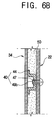
- FIGS. 5A and 5B are partial sectional views to illustrate a combination structure of the main body and the oven of the bread maker according to one embodiment of the present invention; and
- FIGS. 6A and 6B are partial sectional views to illustrate a combination structure of the main body and the oven of the bread maker according to another embodiment of the present invention.
-
- Reference will now be made in detail to the embodiments of the present invention, examples of which are illustrated in the accompanying drawings, wherein like reference numerals refer to like elements throughout.
- As shown in FIGS. 1 and 2, a bread maker according to an aspect of the present invention comprises: a
main body 20, anoven 30 accommodated in themain body 20, a plurality ofheaters 70 to heat the inside of theoven 30, and adoor 80 provided in the front of themain body 20 to open and close theoven 30. - The
main body 20 includes: aframe 22 forming anoven compartment 23, as shown in FIG. 3, in which theoven 30 is accommodated; aframe cover 24, as shown in FIG. 2, to cover the outside of theframe 22, and acontrol panel 90, as shown in FIG. 1, provided in a front side of themain body 20 to allow a user to control the bread maker and to view an operating state of the bread maker. - In upper and lower sides of the
oven 30 are provided an upper kneading drum (not shown) and a lower kneading drum (not shown), which are disposed parallel to each other and alternate clockwise and counterclockwise rotations. On the upper kneadingdrum 36 and the lower kneading drum are wound opposite ends of a mixing bag (not shown) filled with the ingredients for the bread, respectively. Between the upper kneadingdrum 36 and the lower kneading drum is provided a pair of dough-blockingmembers 38 to prevent dough from being kneaded in the mixing bag from moving towards the upper kneadingdrum 36. Further, inside theoven 30 is provided abaking tray 39 shaped like a box with a top opening to contain the completely kneaded dough. Thebaking tray 39 is preferably made of aluminum, steel, or other material that has good heat-resisting property. - The
door 80 is rotatably combined to themain body 20 to selectively open and close a front opening of theoven 30. - In FIGS. 3, 4, 5A and 5B, a
spacing part 40 is provided between theframe 22 and theoven 30 used to combine theframe 22 with theoven 30 and to form a predetermined space to interpose aninsulation member 50 therebetween. - The
frame 22 forms theoven compartment 23 in which theoven 30 is accommodated, and theoven 30 comprises arear part 32 and aside part 34. - As shown in FIG. 5A, on the
rear part 32 of theoven 30, thespacing part 40 protrudes towards theframe 22 to form a space in which theinsulation member 50 is placed, where thespacing part 40 includes at least one first protrudingpart 46 formed with afirst screw hole 41, and at least onefirst screw 49a passing through theframe 22 and inserted into thefirst screw hole 41 of the first protrudingpart 46. - To more securely combine the
frame 22 with theoven 30, as shown in FIG. 5B, preferably, on theside part 34 of theoven 30, thespacing part 40 protrudes towards theframe 22 to form a space in which theinsulation member 50 is placed, wherein thespacing part 40 includes at least onesecond protruding part 48 formed with asecond screw hole 43, and at least onesecond screw 49b passing through theframe 22 and inserted into thesecond screw hole 43 of the second protrudingpart 48. - The first and second protruding
parts second screws parts - The
insulation member 50 is made of mica, glass fiber, etc., and is employed to prevent passage of heat and electricity. - FIGS. 6A and 6B are partial sectional views to illustrate a combination structure of the main body and the oven in the bread maker according to another embodiment of the present invention. In this embodiment, brackets are used instead of the above-described protruding parts shown in FIGS. 3, 4, 5A and 5B.
- As shown in FIG. 6A, on the
rear part 32 of theoven 30, thespacing part 40 protrudes towards theframe 22 to form a space in which theinsulation member 50 is inserted, wherein thespacing part 40 includes at least onefirst bracket 42 formed with afirst screw hole 45, and at least onefirst screw 49a passing through theframe 22 and inserted into thefirst screw hole 45 of thefirst bracket 42. - To more securely combine the
frame 22 with theoven 30, as shown in FIG. 6B, preferably, on theside part 34 of theoven 30, thespacing part 40 protrudes towards theframe 22 to form a space in which theinsulation member 50 is inserted, wherein thespacing part 40 includes at least onesecond bracket 44 formed with asecond screw hole 47, and at least onesecond screw 49b passing through theframe 22 and inserted into thesecond screw hole 47 of thesecond bracket 44. - As described above, preferred embodiments of the present invention provide a bread maker in which an insulation member is interposed between a main body and an oven, thereby preventing not only loss in heat and loss of electricity but also accidents caused due to a leakage current.
- Further, preferred embodiments of the present invention provide a bread maker in which a main body and an oven are securely combined, thereby decreasing unnecessary moment of the bread maker to enhance the durability thereof.
- Although a few embodiments of the present invention have been shown and described, it will be appreciated by those skilled in the art that changes may be made in these embodiments without departing from the principles and spirit of the invention, the scope of which is defined in the appended claims and their equivalents.
- Attention is directed to all papers and documents which are filed concurrently with or previous to this specification in connection with this application and which are open to public inspection with this specification, and the contents of all such papers and documents are incorporated herein by reference.
- All of the features disclosed in this specification (including any accompanying claims, abstract and drawings), and/or all of the steps of any method or process so disclosed, may be combined in any combination, except combinations where at least some of such features and/or steps are mutually exclusive.
- Each feature disclosed in this specification (including any accompanying claims, abstract and drawings) may be replaced by alternative features serving the same, equivalent or similar purpose, unless expressly stated otherwise. Thus, unless expressly stated otherwise, each feature disclosed is one example only of a generic series of equivalent or similar features.
- The invention is not restricted to the details of the foregoing embodiment(s). The invention extends to any novel one, or any novel combination, of the features disclosed in this specification (including any accompanying claims, abstract and drawings), or to any novel one, or any novel combination, of the steps of any method or process so disclosed.
Claims (16)
- A bread maker, comprising:a main body (20) having an oven compartment (23);an oven (30) including a rear part (32) and a side part (34) accommodated in the oven compartment (23) of the main body (20);a spacing part (40) provided between the main body (20) and the oven (30) to form a space between the main body (20) and the oven (30); andan insulation member (50) interposed in the space between the main body (20) and the oven (30).
- The bread maker according to claim 1, wherein the spacing part (46) protrudes towards the rear part (32) of the oven (30) to form the space in which the insulation member (50) is interposed;at least one first protruding part (46) formed with a first screw hole (41); andat least one first screw (49a) passing through the main body (20) and inserted into the first screw hole (41) of the respective first protruding part (46).
- The bread maker according to claim 1 or claim 2, wherein the spacing part (40) protrudes towards the side part (34) of the oven (30) to form the space in which the insulation member (50) is interposed,at least one second protruding part (48) formed with a second screw hole (43); andat least one second screw (49b) passing through the main body (20) and inserted into the second screw hole (43) of the respective second protruding part (48).
- The bread maker according to claim 1, wherein the spacing part (40) protrudes towards the rear part (32) of the oven (30) to form the space in which the insulation member (50) is interposed;at least one first bracket (42) formed with a first screw hole (45); andat least one first screw (49a) passing through the main body (20) and inserted into the first screw hole (45) of the respective first bracket (42).
- The bread maker according to claim 1 or claim 4, wherein the spacing part (40) protrudes towards the side part (34) of the oven (30) to form the space in which the insulation member (50) is interposed,at least one second bracket (44) formed with a second screw hole (47); andat least one second screw (49b) passing through the main body (20) and inserted into the second screw hole(47) of the respective second bracket (44).
- The bread maker according to claim 1, further comprising:a frame (22) forming an oven compartment (23) of the main body (20); a frame cover (24) to cover the outside of the frame (22); anda control panel (90) to allow a user to control the bread maker and to view an operating state of the bread maker.
- The bread maker according to claim 6, wherein a side of the spacing part (40) is adjacent to the frame (22) of the oven (30) to form the space in which the insulation member (50) is interposed.
- A bread maker, comprising:an oven (30) including a rear part (32) and a side part (34); an oven compartment (23);a frame (22) forming the oven compartment (23); anda spacing part (40) provided between the frame (22) and the oven (30) to combine the frame (22) with the oven (30), and to form a predetermined space to interpose an insulation (50).
- The bread maker according to claim 8, wherein the spacing part (40) protrudes towards the frame (22) to form a space in which the insulation member (50) is placed.
- The bread maker according to claim 9, the spacing part (40) further comprising:at least one first protruding part (46) formed with a first screw hole (41); andat least one first screw (49a) passing through the main body (20) and inserted into the first screw hole (41) of the respective first protruding part (46).
- The bread maker according to any one of claims 8 to 10, wherein on a side part (34) of the oven (30), the spacing part (40) protrudes towards the frame (22) to form a space in which the insulation member (50) is placed.
- The bread maker according to claim 11, the spacing part (40) further comprising:at least one second protruding part (48) formed with a second screw hole (43); andat least one second screw (49b) passing through the main body (20) and inserted into the second screw hole (43) of the respective second protruding part (48).
- A bread maker according to any one of claims 1 or 8-12, wherein the spacing part (40) includes at least one first bracket (42) formed with a first screw hole (41).
- The bread maker according to claim 8, wherein the spacing part (40) protrudes towards the rear part (32) of the oven (30) to form the space in which the insulation member (50) is interposed;at least one first bracket (42) formed with a first screw hole (41); andat least one first screw (49a) passing through the main body (20) and inserted into the first screw hole (41) of the respective first protruding part (46).
- The bread maker according to claim 14, wherein the spacing part (40) protrudes towards the side part (34) of the oven (30) to form the space in which the insulation member (50) is interposed,at least one second bracket (44) formed with a second screw hole (47); andat least one second screw (49b) passing through the main body (20) and inserted into the second screw hole (47) of the respective second protruding part (48).
- A bread maker including an oven compartment (23), comprising:a frame (22) to form the oven compartment (23); andan oven (30) including a rear part (32) and a side part (34) accommodated in the oven compartment (23), and separated by a space from the frame (22); andan insulation (50) provided between the frame (22) and the oven (30) which combines the frame (22) with the oven (30).
Applications Claiming Priority (2)
| Application Number | Priority Date | Filing Date | Title |
|---|---|---|---|
| KR2003029125 | 2003-05-07 | ||
| KR1020030029125A KR20040096246A (en) | 2003-05-07 | 2003-05-07 | Oven for baking bread |
Publications (2)
| Publication Number | Publication Date |
|---|---|
| EP1474976A1 true EP1474976A1 (en) | 2004-11-10 |
| EP1474976B1 EP1474976B1 (en) | 2006-05-24 |
Family
ID=36580438
Family Applications (1)
| Application Number | Title | Priority Date | Filing Date |
|---|---|---|---|
| EP03257913A Expired - Lifetime EP1474976B1 (en) | 2003-05-07 | 2003-12-16 | Bread maker |
Country Status (6)
| Country | Link |
|---|---|
| US (1) | US20040221739A1 (en) |
| EP (1) | EP1474976B1 (en) |
| JP (1) | JP2004329893A (en) |
| KR (1) | KR20040096246A (en) |
| CN (1) | CN1270611C (en) |
| DE (1) | DE60305447T2 (en) |
Families Citing this family (1)
| Publication number | Priority date | Publication date | Assignee | Title |
|---|---|---|---|---|
| CN101803621A (en) * | 2010-04-08 | 2010-08-18 | 广东新宝电器股份有限公司 | Energy-saving bread maker |
Citations (3)
| Publication number | Priority date | Publication date | Assignee | Title |
|---|---|---|---|---|
| US4803086A (en) * | 1985-12-23 | 1989-02-07 | Heden-Team Aktiengesellschaft | Automatically making food products such as bread, cakes and the like |
| US5146840A (en) * | 1989-11-22 | 1992-09-15 | Heden-Team Ag | Automatic baking apparatus and mixbag therefore |
| US5532456A (en) * | 1995-03-02 | 1996-07-02 | The Delfield Company | Temperature and humidity controllable doorless oven |
Family Cites Families (15)
| Publication number | Priority date | Publication date | Assignee | Title |
|---|---|---|---|---|
| US3368802A (en) * | 1965-06-11 | 1968-02-13 | Alco Standard Corp | Construction of insulated furnace wall |
| US3523395A (en) * | 1969-03-03 | 1970-08-11 | Johns Manville | Furnace construction system |
| US4059398A (en) * | 1976-04-12 | 1977-11-22 | Jeno F. Paulucci | Food oven |
| US4055745A (en) * | 1976-04-20 | 1977-10-25 | Rodolfo Rodriguez Balaguer | Food cooking oven |
| GB1568603A (en) * | 1977-01-15 | 1980-06-04 | Carborundum Co Ltd | Furnace linings |
| US4245615A (en) * | 1979-04-30 | 1981-01-20 | Magic Chef, Inc. | Modular range construction |
| US4590850A (en) * | 1983-12-27 | 1986-05-27 | Heden Team A.G. | Apparatus for automatically making of food products such as bread, cakes and the like |
| JPS6217530A (en) * | 1985-07-15 | 1987-01-26 | Matsushita Electric Ind Co Ltd | Heated cooking oven with weight detection function |
| US4824644A (en) * | 1987-04-30 | 1989-04-25 | Archeraire Industries, Inc. | Recirculating high velocity hot air sterilizing device having improved internal insulation structure |
| US4851644A (en) * | 1987-05-14 | 1989-07-25 | Delaware Capital Formation, Inc. | Electric combination oven |
| US5164840A (en) * | 1988-08-29 | 1992-11-17 | Matsushita Electric Industrial Co., Ltd. | Apparatus for supplying control codes to sound field reproduction apparatus |
| US5590583A (en) * | 1995-01-13 | 1997-01-07 | Pmi International Corporation | Appliance for making bread and for cooking bagels |
| US5644976A (en) * | 1995-07-31 | 1997-07-08 | Newell Operating Company | Footed cooking utensil |
| DE19957806A1 (en) * | 1999-12-01 | 2001-06-07 | Bsh Bosch Siemens Hausgeraete | Insulating wall |
| US6870136B1 (en) * | 2003-02-03 | 2005-03-22 | Manitowoc Foodservice Companies, Inc. | Proofing cabinet |
-
2003
- 2003-05-07 KR KR1020030029125A patent/KR20040096246A/en not_active Withdrawn
- 2003-12-10 CN CNB2003101201847A patent/CN1270611C/en not_active Expired - Fee Related
- 2003-12-16 DE DE60305447T patent/DE60305447T2/en not_active Expired - Lifetime
- 2003-12-16 EP EP03257913A patent/EP1474976B1/en not_active Expired - Lifetime
-
2004
- 2004-03-23 US US10/806,212 patent/US20040221739A1/en not_active Abandoned
- 2004-03-30 JP JP2004101344A patent/JP2004329893A/en active Pending
Patent Citations (3)
| Publication number | Priority date | Publication date | Assignee | Title |
|---|---|---|---|---|
| US4803086A (en) * | 1985-12-23 | 1989-02-07 | Heden-Team Aktiengesellschaft | Automatically making food products such as bread, cakes and the like |
| US5146840A (en) * | 1989-11-22 | 1992-09-15 | Heden-Team Ag | Automatic baking apparatus and mixbag therefore |
| US5532456A (en) * | 1995-03-02 | 1996-07-02 | The Delfield Company | Temperature and humidity controllable doorless oven |
Also Published As
| Publication number | Publication date |
|---|---|
| KR20040096246A (en) | 2004-11-16 |
| JP2004329893A (en) | 2004-11-25 |
| CN1270611C (en) | 2006-08-23 |
| US20040221739A1 (en) | 2004-11-11 |
| DE60305447T2 (en) | 2007-05-03 |
| DE60305447D1 (en) | 2006-06-29 |
| EP1474976B1 (en) | 2006-05-24 |
| CN1547920A (en) | 2004-11-24 |
Similar Documents
| Publication | Publication Date | Title |
|---|---|---|
| EP1213948B1 (en) | Microwave oven having a toaster | |
| EP2716977A1 (en) | Cooking oven | |
| US10865994B2 (en) | Cooking appliance | |
| US9115903B2 (en) | Oven door | |
| US9228748B2 (en) | Frame structure for an appliance | |
| EP1474976A1 (en) | Bread maker | |
| JP6694583B2 (en) | Toaster oven | |
| CN105686691A (en) | Multifunctional breakfast maker | |
| US20110132350A1 (en) | Oven range | |
| EP1382253B1 (en) | Improvements in and relating to bread makers | |
| EP1474977A1 (en) | Bread maker and oven for bread maker | |
| KR20070065132A (en) | Double Door Microwave | |
| US7246553B2 (en) | Bread maker | |
| EP1474975A2 (en) | Bread maker | |
| EP1474983A1 (en) | Improvements in and relating to bread makers | |
| EP1474987A1 (en) | Bread maker | |
| EP1389893B1 (en) | Microwave oven and more particularly a door for a microwave oven | |
| US20040031792A1 (en) | Microwave oven | |
| JP6697671B2 (en) | Toaster oven | |
| KR20070053564A (en) | Double Door Microwave | |
| JP2020193753A (en) | Toaster oven | |
| JPS63223416A (en) | Door structure of high-frequency heating apparatus | |
| EP1475020A1 (en) | Bread maker | |
| KR20180060657A (en) | Rice cooker | |
| KR20090063419A (en) | Oven |
Legal Events
| Date | Code | Title | Description |
|---|---|---|---|
| PUAI | Public reference made under article 153(3) epc to a published international application that has entered the european phase |
Free format text: ORIGINAL CODE: 0009012 |
|
| 17P | Request for examination filed |
Effective date: 20040105 |
|
| AK | Designated contracting states |
Kind code of ref document: A1 Designated state(s): AT BE BG CH CY CZ DE DK EE ES FI FR GB GR HU IE IT LI LU MC NL PT RO SE SI SK TR |
|
| AX | Request for extension of the european patent |
Extension state: AL LT LV MK |
|
| 17Q | First examination report despatched |
Effective date: 20041221 |
|
| AKX | Designation fees paid |
Designated state(s): DE FR GB SE |
|
| GRAP | Despatch of communication of intention to grant a patent |
Free format text: ORIGINAL CODE: EPIDOSNIGR1 |
|
| GRAS | Grant fee paid |
Free format text: ORIGINAL CODE: EPIDOSNIGR3 |
|
| GRAA | (expected) grant |
Free format text: ORIGINAL CODE: 0009210 |
|
| RIN1 | Information on inventor provided before grant (corrected) |
Inventor name: LEE, TAE-UK Inventor name: LEE, JANG-WOO Inventor name: KIM, CHUL Inventor name: LIM, DONG-BIN Inventor name: SUNG, HAN-JUN Inventor name: KWON, YUNG-HYUN Inventor name: PARK, JAE-RYONG |
|
| AK | Designated contracting states |
Kind code of ref document: B1 Designated state(s): DE FR GB SE |
|
| REG | Reference to a national code |
Ref country code: GB Ref legal event code: FG4D |
|
| REF | Corresponds to: |
Ref document number: 60305447 Country of ref document: DE Date of ref document: 20060629 Kind code of ref document: P |
|
| REG | Reference to a national code |
Ref country code: SE Ref legal event code: TRGR |
|
| ET | Fr: translation filed | ||
| PLBE | No opposition filed within time limit |
Free format text: ORIGINAL CODE: 0009261 |
|
| STAA | Information on the status of an ep patent application or granted ep patent |
Free format text: STATUS: NO OPPOSITION FILED WITHIN TIME LIMIT |
|
| 26N | No opposition filed |
Effective date: 20070227 |
|
| PGFP | Annual fee paid to national office [announced via postgrant information from national office to epo] |
Ref country code: GB Payment date: 20101215 Year of fee payment: 8 |
|
| PGFP | Annual fee paid to national office [announced via postgrant information from national office to epo] |
Ref country code: DE Payment date: 20101208 Year of fee payment: 8 |
|
| PGFP | Annual fee paid to national office [announced via postgrant information from national office to epo] |
Ref country code: FR Payment date: 20111201 Year of fee payment: 9 Ref country code: SE Payment date: 20111118 Year of fee payment: 9 |
|
| PG25 | Lapsed in a contracting state [announced via postgrant information from national office to epo] |
Ref country code: SE Free format text: LAPSE BECAUSE OF NON-PAYMENT OF DUE FEES Effective date: 20121217 |
|
| GBPC | Gb: european patent ceased through non-payment of renewal fee |
Effective date: 20121216 |
|
| REG | Reference to a national code |
Ref country code: FR Ref legal event code: ST Effective date: 20130830 |
|
| REG | Reference to a national code |
Ref country code: DE Ref legal event code: R119 Ref document number: 60305447 Country of ref document: DE Effective date: 20130702 |
|
| PG25 | Lapsed in a contracting state [announced via postgrant information from national office to epo] |
Ref country code: DE Free format text: LAPSE BECAUSE OF NON-PAYMENT OF DUE FEES Effective date: 20130702 |
|
| PG25 | Lapsed in a contracting state [announced via postgrant information from national office to epo] |
Ref country code: GB Free format text: LAPSE BECAUSE OF NON-PAYMENT OF DUE FEES Effective date: 20121216 Ref country code: FR Free format text: LAPSE BECAUSE OF NON-PAYMENT OF DUE FEES Effective date: 20130102 |