EP1474352B1 - Materials handling vehicle mast height sensor - Google Patents
Materials handling vehicle mast height sensor Download PDFInfo
- Publication number
- EP1474352B1 EP1474352B1 EP03707705A EP03707705A EP1474352B1 EP 1474352 B1 EP1474352 B1 EP 1474352B1 EP 03707705 A EP03707705 A EP 03707705A EP 03707705 A EP03707705 A EP 03707705A EP 1474352 B1 EP1474352 B1 EP 1474352B1
- Authority
- EP
- European Patent Office
- Prior art keywords
- mast
- wheel
- sensor
- sensing device
- height sensing
- Prior art date
- Legal status (The legal status is an assumption and is not a legal conclusion. Google has not performed a legal analysis and makes no representation as to the accuracy of the status listed.)
- Expired - Lifetime
Links
Images


Classifications
-
- B—PERFORMING OPERATIONS; TRANSPORTING
- B66—HOISTING; LIFTING; HAULING
- B66F—HOISTING, LIFTING, HAULING OR PUSHING, NOT OTHERWISE PROVIDED FOR, e.g. DEVICES WHICH APPLY A LIFTING OR PUSHING FORCE DIRECTLY TO THE SURFACE OF A LOAD
- B66F9/00—Devices for lifting or lowering bulky or heavy goods for loading or unloading purposes
- B66F9/06—Devices for lifting or lowering bulky or heavy goods for loading or unloading purposes movable, with their loads, on wheels or the like, e.g. fork-lift trucks
- B66F9/075—Constructional features or details
- B66F9/0755—Position control; Position detectors
Definitions
- the present invention relates to a mast height sensing device according to the preamble of claim 1 and a method for sensing the height of a mast. so that the height of a mast, an associated load lifting device, an operator's platform or the like can be determined.
- mast height The importance of determining the height of masts, load lifting devices, such as forks, operator's platforms and the like, generally referred to herein as “mast height", is well known in the art.
- mast height sensing or measuring devices have taken a wide variety of forms.
- a float actuated potentiometer monitoring the liquid level in a sump tank of a hydraulic system controlling mast extension to determine mast height is disclosed in US 4,598,797.
- a disc coupled to a chain wheel used for controlling a mast and having a plurality of slits which pass through a light emitting/detecting path with resulting pulse signals being counted to determine mast height is disclosed in US 4,499,541.
- a gear coupled to a resolver mounted on a stationary upright of a mast assembly is driven by a ladder assembly mounted on a movable upright of the mast assembly and having rungs or teeth engaging and rotating the gear so that the resolver generates a signal representative of mast height.
- the height and speed of a carriage elevated by a screw lift is monitored by a rotary encoder that senses rotary angular displacement of the screw in US 4,782,920.
- direction and distance of movement of a moving mast member of a lift truck relative to a fixed mast member of the truck is measured using a transducer secured to the fixed mast member.
- the transducer includes a potentiometer that is rotated through a gear train extending between the potentiometer and a friction wheel that engages and is rotated by movement of the moving mast member.
- a mast height sensor wherein a rotary shaft encoder is driven by a wheel having a rubber tire mounted thereon that is spring biased against a mast member so that the wheel and hence the shaft of the encoder are rotated by relative movement between the mast members.
- the encoder generates pulses for predetermined degrees of rotation in either direction and by counting these pulses up and down a measure of mast/platform height is derived.
- a mast height sensing device uses a roller bearing with a built in sensor for determining the speed and/or relative displacement of the outer race of the bearing relative to the inner race of the bearing.
- the inner race of the bearing is fixed to a first mast member and the outer race is elastically preloaded against a second mast member to serve as a roller body as the mast members move relative to one another.
- Rotation of the outer race relative to the inner race is monitored using signals generated by the built-in sensor which signals are counted and used in a conventional quadrature direction sensing arrangement to determine direction of movement, mast height and speed of mast movement.
- mast height sensors lack the accuracy required for modern day materials handling vehicle operating systems. Others do not hold up under operating conditions encountered by many materials handling vehicles. Still others do not operate properly when they encounter severe operating conditions. For example, mast height sensor problems have been experienced when materials handling vehicles are operated in big freezers in food warehouses that can be operated at temperatures as low as -40°C (-40°F). Even if a sensor can tolerate such cold temperatures, the vehicles move from the freezers to warmer rooms and/or outside so that condensation forms on the sensors and mast assemblies with the condensation often being in the form of ice.
- the mask height sensing device according to claim 1, and the method for sensing the height of a mask according to claim 20 of the present application wherein a knurled wheel is coupled to a sensor mounted to one of at least two mast members and the wheel is forced into contact with another mast member so that the wheel is rotated when the mast members are moved relative to one another. Rotation of the wheel causes the sensor to generate signals corresponding to the movement of the mast members.
- the signals generated by the sensor are processed conventionally to determine mast height, direction of movement of one or more of the mast members, speed of movement of one or more of the mast members and acceleration of one or more of the mast members, as needed.
- the knurled outer periphery of the wheel is forced into the mast member that it contacts with sufficient force so that a track corresponding to the knurl on the wheel is formed in the contacted mast member and the knurl engages the track for better traction.
- the wheel was forced into the contacted mast member with a force of 26.7 N to 40.0 N (six to nine pounds).
- the thickness of the wheel can be made less than 0.0032 cm (1/8 inch), for example 0.0016 m (1/16 inch).
- Use of a thin wheel enhances operation of the mast height sensor in cold environments, such as food freezers of warehouses where ice may form on the contacted mast member.
- the sensor can be an encoder or a sensor bearing and a heater can be provided for operation in cold environments to ensure rotation of the sensor under such conditions.
- mast height sensor of the present application can be used in any materials handling vehicle wherein the height of masts, load lifting devices, such as forks, operator's platforms and the like (generally referred to herein as "mast height") is to be determined, it will be described with reference to a rider reach lift truck 100 illustrated in Fig. 1.
- the rider reach lift truck 100 includes a power unit 102 which houses a battery for supplying power to a traction motor connected to a steerable wheel and to hydraulic motors which supply power to several different systems including a mast lifting system.
- a caster wheel 104 is mounted at the right rear of the truck 100 while a pair of outriggers 106 are mounted at the forward part of the truck 100.
- the direction of travel and the travel speed of the truck 100 and height, extension, tilt and side shift of forks 108 are controlled from an operator's compartment 110 in the power unit 102.
- a back rest or seat 112 supports the operator in the compartment 110.
- the forks 108 are mounted on a fork carriage mechanism 114 which is in turn mounted on a reach mechanism 116 on a vertical carriage assembly 118.
- the assembly 118 is attached to an extensible mast assembly 120, which includes a fixed, lower mast member 122 and nested movable mast members 124 and 126 which may be made from SAE V-1027 grade of steel.
- a hydraulic cylinder (not shown) is operated to control mast height and thereby the height of the forks 108 which are shown raised in Fig. 1.
- the forks 108 may be tilted through a range shown by the arrow 128 by means of a hydraulic cylinder 130 located between the forks 108 and the fork carriage mechanism 114.
- the forks 108 may also be moved from side to side by a side shift mechanism.
- a mast height sensing device 150 is mounted to the lower mast member 122 and includes a wheel 151 that is forced into the mast member 124 and rotates as the mast member 124 moves relative to the lower mast member 122.
- the mast sensing device 150 comprises a bracket 152 that is used to mount the mast height sensing device to the lower mast member 122.
- An arm 154 is fixed to a shaft 156 mounted for pivotal movement to the bracket 152.
- a spring 158 surrounding the shaft 156 is coupled between the bracket 152 and the arm 154 to spring bias the arm 154 away from the bracket 152.
- the spring 158 would provide a constant force over the range of movement of the arm 154 when the mast height sensing device 150 is installed in the truck 100. Toward that end, the spring 158 is made as long as possible for the available mounting space for the mast height sensing device 150.
- the mast height sensing device 150 can be mounted to a moving mast member so that the wheel 151 of the device is forced into a fixed or other moving mast member.
- the mast height sensing device 150 can be mounted to the mast member 124 with the wheel 151 engaging the lower mast member 122 or the mast member 126.
- a sensor bearing 160 has a fixed outer race 160A, secured to the arm 154 by a retainer 162 and a gasket 164, and a rotating inner race 160B.
- Sensor bearings (well known in the art, see US Patent No. 4,259,637, and commercially available, for example, from SKF USA, Inc.) combine bearings including ball bearings, taper bearings and cylindrical bearings, with integrated sensors that detect rotational movement of the inner race 160B relative to the outer race 160A.
- the sensor generates quadrature output signals that enable an associated circuit or properly programmed computer to determine not only the amount of rotation but also the direction of rotation of the sensor as is well known in the art, for examples of this use of quadrature signals see US Patent No. 4,300,039 and US Patent No.
- the sensor bearing 160 can be replaced by an appropriate shaft encoder as should be apparent to those skilled in the art, see also GB 2 156 099A which is incorporated herein by reference. If a shaft encoder is used in place of the sensor bearing 160, the wheel 151 would be attached to the shaft of the shaft encoder.
- a heating element H and heating element cover HC may also be incorporated into the sensor 150, see Fig. 3.
- a 7.50 watts silicon rubber heater commercially available from Heatron Inc. was conformed and secured to the sensor bearing 160 using a pressure sensitive adhesive.
- the wheel 151 includes a hub 151H that is used to secure the wheel 151 to the inner race 160B by means of a washer 166 and a screw 168.
- the wheel 151 may be made of steel, for example AISI 1144 steel, with a thin, for example 1.27 x 10 -05 /1.78 x 10 -05 m (0.0005/0.0007 inch), nickel high phosphorus plating for corrosion resistance.
- the outer periphery 151A of the wheel 151 is knurled, for example a raised point diamond knurl with a 90° tooth angle and tooth pitch of 1.5875 mm (16 teeth per inch) can be used.
- the knurl is induction hardened to a Rockwell C hardness of Rc 55-60 to a depth of 0.001 ⁇ 0.00025 m (0.040 ⁇ 0.010 inch).
- the knurl can be formed by high pressure metal working, machining, etching or any other appropriate metal forming/processing techniques.
- a variety of wheel thicknesses are contemplated for use in the mast height sensing device of the present application with the thickness of the wheel depending, at least in part, upon the knurl selected for the wheel.
- performance of a mast height sensor is enhanced if the thickness of the wheel is less than around 0.0032 m (1/8 inch).
- Use of such a thin wheel particularly enhances operation of the mast height sensor 150 in cold environments, such as food freezers of warehouses where ice may form on the mast member contacted by the wheel 151.
- ice tends to build up in the knurl and lead to inaccurate and ineffective operation when used on ice covered mast members.
- a wheel thickness that is approximately 0.0016 m (1/16 inch) has proven to be very effective during operation in conventional warehouse conditions as well as the extreme conditions encountered in big freezers in food warehouses that can be operated at temperatures as low as -40°C (-40°F).
- the spring 158 forces the wheel 151 into engagement with the mast member 124 as the arm 154 is pivoted outwardly from the bracket 152. Due to spring and space limitations and the tolerances of the components of the mast assembly 120, the spring force varies over the range of movement of the arm 154 when the mast height sensing device 150 is installed on a materials handling vehicle, such as the lift truck 100. Applicants have determined that a range of force of from about 26.7 N to 40.0 N (six to nine pounds) over this range of movement of the arm 154 provides adequate torque for operation of the mast height sensor 150 in substantially all conditions that the lift truck 100 may be operated.
- a track 170 is formed on the mast member 124 by the knurl on the outer periphery 151A of the wheel 151 with the knurl engaging the track 170 as it rolls along the mast member 124. Formation of the track 170 can be performed by operation of the mast assembly in the factory or after the lift truck 100 is placed in service. The track 170 improves the operation of the mast height sensor 150, particularly in dry operating conditions where a rubber-like wheel can generally provide higher friction.
- FIG. 6 An alternate embodiment of the mast height sensor of the present application is illustrated in Fig. 6 which shows only components of the mast height sensor 150 that are new, modified or replaced in the illustrative embodiment of Figs. 2-5.
- an arm 172 is fixed to a shaft 174 that is mounted to the bracket 152 as shown in Figs. 2-5.
- the arm 172 includes a stepped hub 172H that is used to fix and secure an inner race 176A of a sensor bearing 176 to the arm 172.
- the inner race 176A of the sensor bearing 176 is secured to the hub 172H using a washer 178 and a screw 180.
- An annular wheel 182 is mounted around a sleeve 184 that can be secured to the outer race 176B of the sensor bearing 176 by pressure fitting, adhesive, keying, or any other appropriate technique to prevent the wheel 182 from rotating relative to the sleeve 184.
- the outer periphery 182A of the wheel 182 is knurled, for example as described above relative to the wheel 151, and is then forced into engagement with a mast member, such as one of the mast members 122, 124 or 126 as was the wheel 151 of the embodiment of Figs. 2-5.
- the wheel can be generally centered axially on the sleeve 184, as illustrated, or can be offset from the center.
- a heater (not shown) can be positioned between the inner race 176A and the portion of the hub 172H that extends into the inner race 176A for use of the mast height sensor in cold environments. Alternate heater arrangements for both of the illustrated embodiments as well as other embodiments of the mast sensing device will be apparent to those skilled in the art.
Landscapes
- Engineering & Computer Science (AREA)
- Transportation (AREA)
- Structural Engineering (AREA)
- Civil Engineering (AREA)
- Life Sciences & Earth Sciences (AREA)
- Geology (AREA)
- Mechanical Engineering (AREA)
- Forklifts And Lifting Vehicles (AREA)
Description
- The present invention relates to a mast height sensing device according to the preamble of claim 1 and a method for sensing the height of a mast. so that the height of a mast, an associated load lifting device, an operator's platform or the like can be determined.
- The importance of determining the height of masts, load lifting devices, such as forks, operator's platforms and the like, generally referred to herein as "mast height", is well known in the art. Known mast height sensing or measuring devices have taken a wide variety of forms.
- For example, a float actuated potentiometer monitoring the liquid level in a sump tank of a hydraulic system controlling mast extension to determine mast height is disclosed in US 4,598,797.
- A disc coupled to a chain wheel used for controlling a mast and having a plurality of slits which pass through a light emitting/detecting path with resulting pulse signals being counted to determine mast height is disclosed in US 4,499,541.
- In EP 0 335 196 A1, a gear coupled to a resolver mounted on a stationary upright of a mast assembly is driven by a ladder assembly mounted on a movable upright of the mast assembly and having rungs or teeth engaging and rotating the gear so that the resolver generates a signal representative of mast height.
- The height and speed of a carriage elevated by a screw lift is monitored by a rotary encoder that senses rotary angular displacement of the screw in US 4,782,920.
- In US 5,022,496, the extension and retraction of a cable wound on a spring biased take-up reel mounted on a platform assembly of a turret stockpicker activates an encoder that produces output pulses in direct relation to the amount of rotation of the reel so that the vertical position of the platform assembly can be determined by a microcomputer receiving the pulses.
- In US 3,319,816, direction and distance of movement of a moving mast member of a lift truck relative to a fixed mast member of the truck is measured using a transducer secured to the fixed mast member. The transducer includes a potentiometer that is rotated through a gear train extending between the potentiometer and a friction wheel that engages and is rotated by movement of the moving mast member.
- In GB 2 156 099A, a mast height sensor is disclosed wherein a rotary shaft encoder is driven by a wheel having a rubber tire mounted thereon that is spring biased against a mast member so that the wheel and hence the shaft of the encoder are rotated by relative movement between the mast members. The encoder generates pulses for predetermined degrees of rotation in either direction and by counting these pulses up and down a measure of mast/platform height is derived.
- In US 6,269,913 B1, a mast height sensing device according to the preamble of claim 1 is disclosed, which uses a roller bearing with a built in sensor for determining the speed and/or relative displacement of the outer race of the bearing relative to the inner race of the bearing. The inner race of the bearing is fixed to a first mast member and the outer race is elastically preloaded against a second mast member to serve as a roller body as the mast members move relative to one another. Rotation of the outer race relative to the inner race is monitored using signals generated by the built-in sensor which signals are counted and used in a conventional quadrature direction sensing arrangement to determine direction of movement, mast height and speed of mast movement.
- Unfortunately, many of these mast height sensors lack the accuracy required for modern day materials handling vehicle operating systems. Others do not hold up under operating conditions encountered by many materials handling vehicles. Still others do not operate properly when they encounter severe operating conditions. For example, mast height sensor problems have been experienced when materials handling vehicles are operated in big freezers in food warehouses that can be operated at temperatures as low as -40°C (-40°F). Even if a sensor can tolerate such cold temperatures, the vehicles move from the freezers to warmer rooms and/or outside so that condensation forms on the sensors and mast assemblies with the condensation often being in the form of ice. Such operating conditions are a particular problem for mast height sensors that rely on frictional engagement of a rotating member, such as a rubber covered wheel or an outer race of a bearing sensor, since moisture and ice reduce the friction necessary for their operation. Thus, frictional contacts that may work perfectly well in normal room and warehouse temperatures, fail when operated in and around freezers. Thus, there is a need for an improved mast height sensor for materials handling vehicles that can operate not only under normal operating conditions but also in adverse conditions such as those encountered in and around freezers.
- This need is met by the mask height sensing device according to claim 1, and the method for sensing the height of a mask according to claim 20 of the present application wherein a knurled wheel is coupled to a sensor mounted to one of at least two mast members and the wheel is forced into contact with another mast member so that the wheel is rotated when the mast members are moved relative to one another. Rotation of the wheel causes the sensor to generate signals corresponding to the movement of the mast members. The signals generated by the sensor are processed conventionally to determine mast height, direction of movement of one or more of the mast members, speed of movement of one or more of the mast members and acceleration of one or more of the mast members, as needed. The knurled outer periphery of the wheel is forced into the mast member that it contacts with sufficient force so that a track corresponding to the knurl on the wheel is formed in the contacted mast member and the knurl engages the track for better traction. In a working embodiment of the invention, the wheel was forced into the contacted mast member with a force of 26.7 N to 40.0 N (six to nine pounds). To enhance the versatility of the mast height sensing device of the present application, the thickness of the wheel can be made less than 0.0032 cm (1/8 inch), for example 0.0016 m (1/16 inch). Use of a thin wheel enhances operation of the mast height sensor in cold environments, such as food freezers of warehouses where ice may form on the contacted mast member. The sensor can be an encoder or a sensor bearing and a heater can be provided for operation in cold environments to ensure rotation of the sensor under such conditions.
- A variety of features and advantages of the invention will be apparent from the following description, the accompanying drawings and the appended claims.
-
- Fig. 1 illustrates a rider reach lift truck wherein the mast height sensing device of the present application can be used;
- Fig. 2 is a perspective view of an illustrative embodiment of the mast height sensing device of the present application;
- Fig. 3 is an exploded view of the mast height sensing device of Fig. 2;
- Fig. 4 is a plan view of portions of two mast members showing the mast height sensing device of Figs. 2 and 3 mounted to one of the two mast members and a wheel of the mast height sensing device forced into engagement with another of the two mast members and engaging a track formed thereon by the wheel;
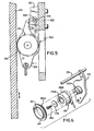
- Fig. 5 is a sectional view of the mast height sensor and the two mast members of Fig. 4 taken along the section line 5-5 of Fig. 4; and
- Fig. 6 is an exploded view of an alternate illustrative embodiment of the mast height sensing device showing parts of the device that are new, modified or replaced for this embodiment.
- While the mast height sensor of the present application can be used in any materials handling vehicle wherein the height of masts, load lifting devices, such as forks, operator's platforms and the like (generally referred to herein as "mast height") is to be determined, it will be described with reference to a rider
reach lift truck 100 illustrated in Fig. 1. The riderreach lift truck 100 includes apower unit 102 which houses a battery for supplying power to a traction motor connected to a steerable wheel and to hydraulic motors which supply power to several different systems including a mast lifting system. Acaster wheel 104 is mounted at the right rear of thetruck 100 while a pair ofoutriggers 106 are mounted at the forward part of thetruck 100. - The direction of travel and the travel speed of the
truck 100 and height, extension, tilt and side shift offorks 108 are controlled from an operator'scompartment 110 in thepower unit 102. A back rest orseat 112 supports the operator in thecompartment 110. Theforks 108 are mounted on afork carriage mechanism 114 which is in turn mounted on areach mechanism 116 on avertical carriage assembly 118. Theassembly 118 is attached to anextensible mast assembly 120, which includes a fixed,lower mast member 122 and nestedmovable mast members forks 108 which are shown raised in Fig. 1. Theforks 108 may be tilted through a range shown by thearrow 128 by means of ahydraulic cylinder 130 located between theforks 108 and thefork carriage mechanism 114. Theforks 108 may also be moved from side to side by a side shift mechanism. - To measure the relative direction and distance of movement of the
mast members height sensing device 150, shown in Figs. 2-5, is mounted to thelower mast member 122 and includes awheel 151 that is forced into themast member 124 and rotates as themast member 124 moves relative to thelower mast member 122. Themast sensing device 150 comprises abracket 152 that is used to mount the mast height sensing device to thelower mast member 122. Anarm 154 is fixed to ashaft 156 mounted for pivotal movement to thebracket 152. Aspring 158 surrounding theshaft 156 is coupled between thebracket 152 and thearm 154 to spring bias thearm 154 away from thebracket 152. Ideally, thespring 158 would provide a constant force over the range of movement of thearm 154 when the mastheight sensing device 150 is installed in thetruck 100. Toward that end, thespring 158 is made as long as possible for the available mounting space for the mastheight sensing device 150. If desired, the mastheight sensing device 150 can be mounted to a moving mast member so that thewheel 151 of the device is forced into a fixed or other moving mast member. For example, the mastheight sensing device 150 can be mounted to themast member 124 with thewheel 151 engaging thelower mast member 122 or themast member 126. - A sensor bearing 160 has a fixed
outer race 160A, secured to thearm 154 by aretainer 162 and agasket 164, and a rotatinginner race 160B. Sensor bearings (well known in the art, see US Patent No. 4,259,637, and commercially available, for example, from SKF USA, Inc.) combine bearings including ball bearings, taper bearings and cylindrical bearings, with integrated sensors that detect rotational movement of theinner race 160B relative to theouter race 160A. The sensor generates quadrature output signals that enable an associated circuit or properly programmed computer to determine not only the amount of rotation but also the direction of rotation of the sensor as is well known in the art, for examples of this use of quadrature signals see US Patent No. 4,300,039 and US Patent No. 4,982,189 which are incorporated herein by reference. Thesensor bearing 160 can be replaced by an appropriate shaft encoder as should be apparent to those skilled in the art, see also GB 2 156 099A which is incorporated herein by reference. If a shaft encoder is used in place of thesensor bearing 160, thewheel 151 would be attached to the shaft of the shaft encoder. To ensure proper operation of themast height sensor 150 in cold environments, a heating element H and heating element cover HC may also be incorporated into thesensor 150, see Fig. 3. In a working embodiment of themast height sensor 150, a 7.50 watts silicon rubber heater commercially available from Heatron Inc. was conformed and secured to thesensor bearing 160 using a pressure sensitive adhesive. - The
wheel 151 includes ahub 151H that is used to secure thewheel 151 to theinner race 160B by means of awasher 166 and ascrew 168. Thewheel 151 may be made of steel, for example AISI 1144 steel, with a thin, for example 1.27 x 10-05/1.78 x 10-05 m (0.0005/0.0007 inch), nickel high phosphorus plating for corrosion resistance. Theouter periphery 151A of thewheel 151 is knurled, for example a raised point diamond knurl with a 90° tooth angle and tooth pitch of 1.5875 mm (16 teeth per inch) can be used. The knurl is induction hardened to a Rockwell C hardness of Rc 55-60 to a depth of 0.001 ± 0.00025 m (0.040 ± 0.010 inch). The knurl can be formed by high pressure metal working, machining, etching or any other appropriate metal forming/processing techniques. - A variety of wheel thicknesses are contemplated for use in the mast height sensing device of the present application with the thickness of the wheel depending, at least in part, upon the knurl selected for the wheel. However, applicants have determined that performance of a mast height sensor is enhanced if the thickness of the wheel is less than around 0.0032 m (1/8 inch). Use of such a thin wheel particularly enhances operation of the
mast height sensor 150 in cold environments, such as food freezers of warehouses where ice may form on the mast member contacted by thewheel 151. For wheels using the identified knurl and having a thickness greater than around 0.0032 m (1/8 inch) ice tends to build up in the knurl and lead to inaccurate and ineffective operation when used on ice covered mast members. In a working embodiment of themast height sensor 150, a wheel thickness that is approximately 0.0016 m (1/16 inch)has proven to be very effective during operation in conventional warehouse conditions as well as the extreme conditions encountered in big freezers in food warehouses that can be operated at temperatures as low as -40°C (-40°F). - To ensure that the
wheel 151 is engaged with themast member 124 and to increase the torque exerted on thewheel 151 and hence thebearing 160, thespring 158 forces thewheel 151 into engagement with themast member 124 as thearm 154 is pivoted outwardly from thebracket 152. Due to spring and space limitations and the tolerances of the components of themast assembly 120, the spring force varies over the range of movement of thearm 154 when the mastheight sensing device 150 is installed on a materials handling vehicle, such as thelift truck 100. Applicants have determined that a range of force of from about 26.7 N to 40.0 N (six to nine pounds) over this range of movement of thearm 154 provides adequate torque for operation of themast height sensor 150 in substantially all conditions that thelift truck 100 may be operated. When a 26.7 N to 40.0 N (six to nine pound) range of force is used to apply thewheel 151 to themast member 124, applicants discovered that atrack 170 is formed on themast member 124 by the knurl on theouter periphery 151A of thewheel 151 with the knurl engaging thetrack 170 as it rolls along themast member 124. Formation of thetrack 170 can be performed by operation of the mast assembly in the factory or after thelift truck 100 is placed in service. Thetrack 170 improves the operation of themast height sensor 150, particularly in dry operating conditions where a rubber-like wheel can generally provide higher friction. - An alternate embodiment of the mast height sensor of the present application is illustrated in Fig. 6 which shows only components of the
mast height sensor 150 that are new, modified or replaced in the illustrative embodiment of Figs. 2-5. In the alternate embodiment of Fig. 6, anarm 172 is fixed to ashaft 174 that is mounted to thebracket 152 as shown in Figs. 2-5. Thearm 172 includes a steppedhub 172H that is used to fix and secure aninner race 176A of asensor bearing 176 to thearm 172. Theinner race 176A of thesensor bearing 176 is secured to thehub 172H using awasher 178 and ascrew 180. Anannular wheel 182 is mounted around asleeve 184 that can be secured to theouter race 176B of thesensor bearing 176 by pressure fitting, adhesive, keying, or any other appropriate technique to prevent thewheel 182 from rotating relative to thesleeve 184. Theouter periphery 182A of thewheel 182 is knurled, for example as described above relative to thewheel 151, and is then forced into engagement with a mast member, such as one of themast members wheel 151 of the embodiment of Figs. 2-5. The wheel can be generally centered axially on thesleeve 184, as illustrated, or can be offset from the center. A heater (not shown) can be positioned between theinner race 176A and the portion of thehub 172H that extends into theinner race 176A for use of the mast height sensor in cold environments. Alternate heater arrangements for both of the illustrated embodiments as well as other embodiments of the mast sensing device will be apparent to those skilled in the art. - While the method of sensing the height of a mast of a materials handling vehicle in accordance with the present invention should be apparent from the above description of the sensor, the method will now be briefly described for sake of clarity. In particular, a method for sensing the height of a mast of a materials handling vehicle having a mast assembly comprising at least a first mast member and a second mast member with the first mast member being moveable relative to the second mast member comprises mounting a sensor on one of the first and second mast members, coupling a knurled wheel to the sensor so that rotation of the wheel causes the sensor to generate corresponding signals, and forcing the wheel into another of the first and second mast members so that the wheel contacts the another of the first and second mast members and is rotated by the another mast member during extension and retraction of the first mast member relative to the second mast member.
- Having thus described the invention of the present application in detail and by reference to preferred embodiments thereof, it will be apparent that modifications and variations are possible without departing from the scope of the invention defined in the appended claims.
Claims (29)
- A mast height sensing device (150) for a materials handling vehicle (100) having a mast assembly (120) comprising at least a first mast member (124) and a second mast member (122), said first mast member being moveable relative to said second mast member, said mast height sensing device comprising:a sensor;a wheel (151,182) coupled to said sensor such that rotation of said wheel causes said sensor to generate corresponding signals; anda mount (152) for securing said sensor to one of said first and second mast members so that said wheel is engaged with another of said first and second mast members and is rotated by extension and retraction of said first mast member relative to said second mast member, characterised by said wheel having an outer periphery (151A, 182A) that is knurled.
- A mast height sensing device (150) as claimed in claim 1 wherein said mount includes a spring (158) forcing said wheel (151,182) into engagement with said another of said first and second mast members (122, 124).
- A mast height sensing device (150) as claimed in claim 2 wherein a force of said spring (158) is sufficient so that the knurl of said wheel (151, 182) forms a track (170) in said another of said first and second mast members (122, 124), said knurl engaging said track.
- A mast height sensing device (150) as claimed in claim 3 wherein said force of said spring (158) is within a range of about 26.7 N to 40.0 N (six to nine pounds).
- A mast height sensing device (150) as claimed in claim 1 wherein said wheel (151, 182) has a thickness of less than about 0.0032 m (1/8 inch).
- A mast height sensing device (150) as claimed in claim 5 wherein said wheel (151, 182) has a thickness of about 0.0016 m (1/16 inch).
- A mast height sensing device (150) as claimed in claim 1 wherein said sensor comprises a shaft encoder and said wheel is connected to a shaft of said shaft encoder.
- A mast height sensing device (150) as claimed in claim 1 wherein:said sensor comprises a sensor bearing (160, 176); andsaid wheel (151) comprises a hub (151H) extending from the center thereof, said hub being secured to an inner race (160B) of said sensor bearing for rotation.
- A mast height sensing device (150) as claimed in claim 8 further comprising a heating element (H) associated with said sensor bearing (160).
- A mast height sensing device (150) as claimed in claim 1 wherein:said sensor comprises a sensor bearing (176); andsaid wheel (182) is mounted to an outer race (176B) of said sensor bearing.
- A mast height sensing device (150) as claimed in claim 10 wherein said wheel (182) is annular and mounted over said outer race (176B) of said sensor bearing (176).
- A mast height sensing device (150) as claimed in claim 11 wherein said wheel (182) is generally centered over said outer race (176B) of said sensor bearing (176).
- A mast height sensing device (150) as claimed in claim 1, wherein said wheel is forced into said another of said first and second mast members and is sufficiently thin that when said wheel engages ice formed on said another mast member the ice does not build up on said knurled outer periphery.
- A mast height sensing device (150) as claimed in claim 13 wherein said wheel (151, 182) is less than about 0.0032 m (1/8 inch) in thickness.
- A mast height sensing device (150) as claimed in claim 14 wherein said wheel (151, 182) is forced into said another mast member (122, 124) with a force of about 26.7 N to 40.0 N (six to nine pounds).
- A mast height sensing device (150) as claimed in claim 13 wherein said wheel (151, 182) is about 0.0016 m (1/16 inch) in thickness.
- A mast height sensing device (150) as claimed in claim 16 wherein said wheel (151, 182) is forced into said another mast member (122, 124) with a force of about 26.7 N to 40.0 N (six to nine pounds).
- A mast height sensing device (150) as claimed in claim 1, wherein said wheel is forced into said another mast member (122, 124) with sufficient force that said wheel forms a track (170) in said another mast member, said knurl engaging said track.
- A mast height sensing device (150) according to claim 1, wherein said wheel is forced into engagement with said another of said first and second mast members and has a thickness of less than about 0.0032 m (1/8 inch).
- A method for sensing the height of a mast of a materials handling vehicle (100), said vehicle having a mast assembly (120) comprising at least a first mast member (124) and a second mast member (122), said first mast member being moveable relative to said second mast member, said method comprising the steps of:mounting a sensor on one of said first and second mast members;coupling a knurled wheel (151, 182) to said sensor so that rotation of said wheel causes said sensor to generate corresponding signals; andforcing said wheel into another of said first and second mast members so that said wheel contacts said another of said first and second mast members and is rotated by said another mast member during extension and retraction of said first mast member relative to said second mast member.
- A method as claimed in claim 20 wherein said step of forcing said wheel (151, 182) into said another of said first and second mast members (122, 124) is performed with sufficient force so as to form a track (170) on said another of said first and second mast members as said first mast member is extended and retracted relative to said second mast member.
- A method as claimed in claim 21 wherein said track (170) is formed during manufacture of said vehicle (100) by extending and retracting said first mast member (124) relative to said second mast member (122).
- A method as claimed in claim 21 wherein said track (170) is formed during normal operation of said vehicle (100).
- A method as claimed in claim 20 wherein said sensor comprises a sensor bearing (160) and said step of coupling a knurled wheel (151) to said sensor so that rotation of said wheel causes rotation of said sensor comprises the step of:providing a knurled wheel having a central hub (151H); andsecuring said central hub to an inner race (160B) of said sensor bearing.
- A method as claimed in claim 20 wherein said sensor comprises a sensor bearing (176) and said step of coupling a knurled wheel (182) to said sensor so that rotation of said wheel causes said sensor to generate corresponding signals comprises the steps of:providing an annular knurled wheel; andsecuring said annular knurled wheel to an outer race (176B) of said sensor bearing.
- A method as claimed in claim 25 wherein said step of securing said annular knurled wheel (182) to an outer race (176B) of said sensor bearing (176) comprises the step of securing said annular knurled wheel over said outer race of said sensor bearing.
- A method as claimed in claim 26 further comprising the step of generally centering said knurled wheel (182) over said outer race (176B) of said sensor bearing (176).
- A method as claimed in claim 20 wherein said knurled wheel (151, 182) has a thickness less than about 0.0032 m (1/8 inch).
- A method as claimed in claim 28 wherein said knurled wheel (151, 182) has a thickness of about 0.0016 m (1/16 inch).
Applications Claiming Priority (3)
| Application Number | Priority Date | Filing Date | Title |
|---|---|---|---|
| US68709 | 2002-02-06 | ||
| US10/068,709 US6533076B1 (en) | 2002-02-06 | 2002-02-06 | Materials handling vehicle mast height sensor |
| PCT/US2003/003313 WO2003066508A1 (en) | 2002-02-06 | 2003-02-05 | Materials handling vehicle mast height sensor |
Publications (2)
| Publication Number | Publication Date |
|---|---|
| EP1474352A1 EP1474352A1 (en) | 2004-11-10 |
| EP1474352B1 true EP1474352B1 (en) | 2006-09-13 |
Family
ID=22084232
Family Applications (1)
| Application Number | Title | Priority Date | Filing Date |
|---|---|---|---|
| EP03707705A Expired - Lifetime EP1474352B1 (en) | 2002-02-06 | 2003-02-05 | Materials handling vehicle mast height sensor |
Country Status (5)
| Country | Link |
|---|---|
| US (1) | US6533076B1 (en) |
| EP (1) | EP1474352B1 (en) |
| AU (1) | AU2003208980A1 (en) |
| DE (1) | DE60308323T2 (en) |
| WO (1) | WO2003066508A1 (en) |
Families Citing this family (16)
| Publication number | Priority date | Publication date | Assignee | Title |
|---|---|---|---|---|
| DE10153531A1 (en) * | 2001-10-30 | 2003-05-15 | Bosch Gmbh Robert | Sensor arrangement for measuring the deflection of a moving part of a mechanical device |
| DE10248655A1 (en) * | 2002-10-18 | 2004-04-29 | Still Wagner Gmbh & Co. Kg | Industrial truck with a mast and a temperature switch |
| US7344351B2 (en) * | 2003-09-12 | 2008-03-18 | Deere & Company | Electronic boom height sensor |
| US7196527B2 (en) * | 2004-02-17 | 2007-03-27 | Stridsberg Innovation Ab | Redundant compact encoders |
| US7121608B2 (en) * | 2004-09-23 | 2006-10-17 | Crown Equipment Corporation | Rotating and/or swiveling seat |
| US7059680B2 (en) * | 2004-09-23 | 2006-06-13 | Crown Equipment Corporation | Seat repositioning device with release on control handle |
| US7520567B2 (en) * | 2004-09-23 | 2009-04-21 | Crown Equipment Corporation | Systems and methods for seat repositioning |
| US7344000B2 (en) * | 2004-09-23 | 2008-03-18 | Crown Equipment Corporation | Electronically controlled valve for a materials handling vehicle |
| US8230976B2 (en) * | 2008-04-16 | 2012-07-31 | The Raymond Corporation | Pallet truck with calculated fork carriage height |
| EP2331448B1 (en) | 2008-09-12 | 2016-11-02 | Crown Equipment Corporation | Monomast for a materials handling vehicle |
| DE102010039471B4 (en) * | 2010-08-18 | 2014-02-13 | Robert Bosch Gmbh | Method and device for determining a lifting height of a working machine |
| BR112013020758A2 (en) | 2011-02-16 | 2016-10-18 | Crown Equip Corp | material handling vehicle |
| EP2527288B1 (en) | 2011-05-27 | 2013-08-21 | Atlet AB | Fork lift truck with automatic lift height control |
| US9440827B2 (en) * | 2014-03-20 | 2016-09-13 | Jungheinrich Aktiengesellschaft | Lift mast height sensor for an industrial truck |
| CN105417446A (en) * | 2015-12-29 | 2016-03-23 | 合肥搬易通科技发展有限公司 | Lifting height positioning device of fork lifter |
| US11565923B2 (en) | 2019-02-19 | 2023-01-31 | Crown Equipment Corporation | Chain slack detection system |
Family Cites Families (44)
| Publication number | Priority date | Publication date | Assignee | Title |
|---|---|---|---|---|
| US2134025A (en) | 1936-05-02 | 1938-10-25 | Homer L Bredouw | Sounding apparatus |
| US3319816A (en) | 1965-03-15 | 1967-05-16 | Clark Equipment Co | Tilt and hoist control mechanism for a lift truck |
| US3572484A (en) | 1968-11-14 | 1971-03-30 | Eaton Yale & Towne | Control mechanism comprising motor and brakes responsive to counter means |
| US3589535A (en) | 1969-08-26 | 1971-06-29 | Simon Handling Eng Ltd | Transporting and stacking means with a correlated position sensing and load sensing means |
| US3811192A (en) | 1972-04-26 | 1974-05-21 | Readx Inc | Height gauge |
| US3812589A (en) | 1972-05-25 | 1974-05-28 | Dillon W & Co Inc | Boom length indicator |
| US3816003A (en) | 1973-03-12 | 1974-06-11 | Dynamics Res Corp | Sealed linear encoder |
| US3936943A (en) | 1974-04-15 | 1976-02-10 | Bullard Iii Edward P | Measuring system |
| US3955073A (en) | 1974-05-14 | 1976-05-04 | Carew Victor E | Caliper type dimensional sensing devices and associated electronic mensuration, data processing and printout system |
| JPS5237349A (en) | 1975-09-17 | 1977-03-23 | Mitsubishi Electric Corp | Device for generating signals representative of the position of an elevator |
| US4074794A (en) | 1975-10-31 | 1978-02-21 | Towmotor Corporation | Height indicator and control for fork lift trucks |
| IN149928B (en) | 1977-07-22 | 1982-06-05 | Ransome Hoffmann Pollard | |
| US4122957A (en) | 1977-10-06 | 1978-10-31 | The Raymond Corporation | Lift truck having height indicating means |
| US4210865A (en) | 1977-12-12 | 1980-07-01 | Chaika Leopold I | Position sensor of linearly moving bodies |
| US4266215A (en) | 1978-11-16 | 1981-05-05 | The Raymond Corporation | Reversible incremental encoding method and apparatus |
| US4547844A (en) | 1979-03-16 | 1985-10-15 | The Raymond Corporation | Shelf height selector |
| JPS5633399A (en) | 1979-08-20 | 1981-04-03 | Komatsu Forklift | Cargo work car |
| US4300039A (en) | 1979-11-13 | 1981-11-10 | Rca Corporation | Incremental encoder |
| US4511974A (en) | 1981-02-04 | 1985-04-16 | Kabushiki Kaisha Toyoda Jidoshokki Seisakusho | Load condition indicating method and apparatus for forklift truck |
| US4509127A (en) | 1981-03-31 | 1985-04-02 | Kabushiki Kaisha Toyoda Jidoh Shokki Seisakusho | Control device for loading and unloading mechanism |
| JPS57158696U (en) | 1981-03-31 | 1982-10-05 | ||
| US4472713A (en) | 1981-11-06 | 1984-09-18 | Itek Corporation | Optical encoder with integral flexible coupler |
| US4443888A (en) | 1982-03-29 | 1984-04-17 | Litton Industrial Products, Inc. | SID Monitor |
| GB2156099A (en) | 1984-03-15 | 1985-10-02 | T P S Engineering Services Ltd | Height control for elevating apparatus |
| US4598797A (en) | 1984-04-13 | 1986-07-08 | Clark Equipment Company | Travel/lift inhibit control |
| US4697144A (en) | 1984-04-19 | 1987-09-29 | Verify Electronics Limited | Position sensing apparatus |
| JPS61281902A (en) | 1985-06-07 | 1986-12-12 | Toshiba Mach Co Ltd | Method and apparatus for detecting absolute position |
| US4646085A (en) | 1985-08-02 | 1987-02-24 | Leupold & Stevens, Inc. | Shaft position encoder apparatus with logic and decoder |
| US4879508A (en) | 1986-04-04 | 1989-11-07 | Mitutoyo Corporation | Capacitance-type measuring device for absolute measurement of positions |
| CH666122A5 (en) | 1986-04-10 | 1988-06-30 | Hans Ulrich Meyer | CAPACITIVE POSITION SENSOR. |
| US4747215A (en) | 1986-11-24 | 1988-05-31 | Jack Waikas | Electronic tape measure |
| EP0335196A1 (en) | 1988-03-31 | 1989-10-04 | Caterpillar Industrial Inc. | Apparatus and method for controllably positioning a lift mast assembly |
| US4924151A (en) * | 1988-09-30 | 1990-05-08 | Lutron Electronics Co., Inc. | Multi-zone, multi-scene lighting control system |
| US5011358A (en) | 1988-10-25 | 1991-04-30 | Andersen Eric T | Height indicator for a fork lift truck |
| US5274203A (en) * | 1989-06-30 | 1993-12-28 | Otis Elevator Company | "Smart" position transducer system for elevators |
| US5103226A (en) | 1989-12-05 | 1992-04-07 | Crown Equipment Corporation | Height sensor for turret stockpicker |
| US5022496A (en) | 1989-12-05 | 1991-06-11 | Crown Equipment Corporation | Slowdown during staging of a turret stockpicker |
| US5749696A (en) | 1992-07-23 | 1998-05-12 | Scott Westlake | Height and tilt indicator for forklift truck |
| US5687081A (en) | 1994-12-30 | 1997-11-11 | Crown Equipment Corporation | Lift truck control system |
| EP0743508A2 (en) | 1995-05-16 | 1996-11-20 | Mitutoyo Corporation | Induced current position transducer |
| DE19520388C2 (en) | 1995-06-02 | 1997-04-10 | Asm Automation Sensorik Messte | Measuring cable displacement sensor with bowl-shaped housing |
| US6002250A (en) | 1996-05-13 | 1999-12-14 | Mitutoyo Corporation | Electronic linear scale using a self-contained, low-power inductive position transducer |
| DE19731687A1 (en) | 1997-07-23 | 1999-02-04 | Steinbock Boss Gmbh Foerdertec | Industrial truck |
| JP5155505B2 (en) * | 2000-04-27 | 2013-03-06 | インベンテイオ・アクテイエンゲゼルシヤフト | Elevator passenger evacuation device |
-
2002
- 2002-02-06 US US10/068,709 patent/US6533076B1/en not_active Expired - Lifetime
-
2003
- 2003-02-05 AU AU2003208980A patent/AU2003208980A1/en not_active Abandoned
- 2003-02-05 WO PCT/US2003/003313 patent/WO2003066508A1/en not_active Ceased
- 2003-02-05 EP EP03707705A patent/EP1474352B1/en not_active Expired - Lifetime
- 2003-02-05 DE DE60308323T patent/DE60308323T2/en not_active Expired - Lifetime
Also Published As
| Publication number | Publication date |
|---|---|
| US6533076B1 (en) | 2003-03-18 |
| EP1474352A1 (en) | 2004-11-10 |
| WO2003066508A1 (en) | 2003-08-14 |
| DE60308323T2 (en) | 2007-09-20 |
| DE60308323D1 (en) | 2006-10-26 |
| AU2003208980A1 (en) | 2003-09-02 |
Similar Documents
| Publication | Publication Date | Title |
|---|---|---|
| US6533076B1 (en) | Materials handling vehicle mast height sensor | |
| US6293022B1 (en) | Mounting structure for wheel angle detector and rotation amount detector for vehicle wheel | |
| EP1329727A8 (en) | Rotation-speed sensor device | |
| US9766627B2 (en) | Displacement sensor for a robotic vehicle detecting a lift event and a collision event | |
| US6269913B1 (en) | Roller position monitoring device for an industrial lift truck | |
| US5002404A (en) | Radial rolling bearings | |
| US11531039B2 (en) | Wheel assembly with sensor for measuring wheel movement | |
| EP0236335B1 (en) | Axle assembly | |
| KR100817634B1 (en) | Method for automatically positioning the right and left wheels of a vehicle | |
| KR950014942B1 (en) | Device for measuring rotational parameters of the axis of rotation | |
| US20080304779A1 (en) | Wheel Bearing with Sensor | |
| US6536267B2 (en) | Angular position sensor unit | |
| EP3438039A1 (en) | Self-propelled vehicle equipped with a lifting unit | |
| US5365674A (en) | Device for measuring the displacement of a swivel of a drilling mast | |
| EP4025917A1 (en) | Axle assembly and vehicle comprising such an axle assembly | |
| JP2003271242A (en) | Self-propelled equipment | |
| JP2005158052A (en) | System and method for determining at least one parameter of at least one rotating member using a reference signal and a velocity signal | |
| CN114834528A (en) | Angle measuring device and semi-trailer type transport vehicle | |
| CN219194406U (en) | Cargo handling machine | |
| KR0107585Y1 (en) | Constant velocity joint with detection of vehicle speed | |
| JPH03182860A (en) | Vehicle speed detector for reach type fork lift | |
| JP2007078596A (en) | Bearing with sensor for wheel | |
| KR20060104191A (en) | Torque sensor of automotive steering system | |
| MXPA96004929A (en) | Apparatus for following the movement of a vehicle without conduct |
Legal Events
| Date | Code | Title | Description |
|---|---|---|---|
| PUAI | Public reference made under article 153(3) epc to a published international application that has entered the european phase |
Free format text: ORIGINAL CODE: 0009012 |
|
| 17P | Request for examination filed |
Effective date: 20040901 |
|
| AK | Designated contracting states |
Kind code of ref document: A1 Designated state(s): AT BE BG CH CY CZ DE DK EE ES FI FR GB GR HU IE IT LI LU MC NL PT SE SI SK TR |
|
| AX | Request for extension of the european patent |
Extension state: AL LT LV MK RO |
|
| 17Q | First examination report despatched |
Effective date: 20050217 |
|
| GRAP | Despatch of communication of intention to grant a patent |
Free format text: ORIGINAL CODE: EPIDOSNIGR1 |
|
| GRAS | Grant fee paid |
Free format text: ORIGINAL CODE: EPIDOSNIGR3 |
|
| GRAA | (expected) grant |
Free format text: ORIGINAL CODE: 0009210 |
|
| AK | Designated contracting states |
Kind code of ref document: B1 Designated state(s): DE FR GB |
|
| REG | Reference to a national code |
Ref country code: GB Ref legal event code: FG4D |
|
| REF | Corresponds to: |
Ref document number: 60308323 Country of ref document: DE Date of ref document: 20061026 Kind code of ref document: P |
|
| ET | Fr: translation filed | ||
| PLBE | No opposition filed within time limit |
Free format text: ORIGINAL CODE: 0009261 |
|
| STAA | Information on the status of an ep patent application or granted ep patent |
Free format text: STATUS: NO OPPOSITION FILED WITHIN TIME LIMIT |
|
| 26N | No opposition filed |
Effective date: 20070614 |
|
| REG | Reference to a national code |
Ref country code: FR Ref legal event code: PLFP Year of fee payment: 14 |
|
| REG | Reference to a national code |
Ref country code: FR Ref legal event code: PLFP Year of fee payment: 15 |
|
| REG | Reference to a national code |
Ref country code: FR Ref legal event code: PLFP Year of fee payment: 16 |
|
| PGFP | Annual fee paid to national office [announced via postgrant information from national office to epo] |
Ref country code: GB Payment date: 20220223 Year of fee payment: 20 Ref country code: DE Payment date: 20220217 Year of fee payment: 20 |
|
| PGFP | Annual fee paid to national office [announced via postgrant information from national office to epo] |
Ref country code: FR Payment date: 20220216 Year of fee payment: 20 |
|
| REG | Reference to a national code |
Ref country code: DE Ref legal event code: R071 Ref document number: 60308323 Country of ref document: DE |
|
| REG | Reference to a national code |
Ref country code: GB Ref legal event code: PE20 Expiry date: 20230204 |
|
| PG25 | Lapsed in a contracting state [announced via postgrant information from national office to epo] |
Ref country code: GB Free format text: LAPSE BECAUSE OF EXPIRATION OF PROTECTION Effective date: 20230204 |
|
| P01 | Opt-out of the competence of the unified patent court (upc) registered |
Effective date: 20230529 |