EP1474338B1 - Can end - Google Patents
Can end Download PDFInfo
- Publication number
- EP1474338B1 EP1474338B1 EP03739439A EP03739439A EP1474338B1 EP 1474338 B1 EP1474338 B1 EP 1474338B1 EP 03739439 A EP03739439 A EP 03739439A EP 03739439 A EP03739439 A EP 03739439A EP 1474338 B1 EP1474338 B1 EP 1474338B1
- Authority
- EP
- European Patent Office
- Prior art keywords
- wall
- flat portion
- panel
- score
- tab
- Prior art date
- Legal status (The legal status is an assumption and is not a legal conclusion. Google has not performed a legal analysis and makes no representation as to the accuracy of the status listed.)
- Expired - Lifetime
Links
Images

Classifications
-
- B—PERFORMING OPERATIONS; TRANSPORTING
- B65—CONVEYING; PACKING; STORING; HANDLING THIN OR FILAMENTARY MATERIAL
- B65D—CONTAINERS FOR STORAGE OR TRANSPORT OF ARTICLES OR MATERIALS, e.g. BAGS, BARRELS, BOTTLES, BOXES, CANS, CARTONS, CRATES, DRUMS, JARS, TANKS, HOPPERS, FORWARDING CONTAINERS; ACCESSORIES, CLOSURES, OR FITTINGS THEREFOR; PACKAGING ELEMENTS; PACKAGES
- B65D17/00—Rigid or semi-rigid containers specially constructed to be opened by cutting or piercing, or by tearing of frangible members or portions
- B65D17/28—Rigid or semi-rigid containers specially constructed to be opened by cutting or piercing, or by tearing of frangible members or portions at lines or points of weakness
- B65D17/401—Rigid or semi-rigid containers specially constructed to be opened by cutting or piercing, or by tearing of frangible members or portions at lines or points of weakness characterised by having the line of weakness provided in an end wall
- B65D17/4011—Rigid or semi-rigid containers specially constructed to be opened by cutting or piercing, or by tearing of frangible members or portions at lines or points of weakness characterised by having the line of weakness provided in an end wall for opening completely by means of a tearing tab
Definitions
- This invention relates to a can end and, in particular to a can end which is adapted for opening by at least two different methods.
- Easy open can ends in which a ring pull or tab is provided for removal of a panel defined by a score line
- Full aperture easy open ends in which the score line surrounds the whole of a centre panel adjacent to the circumferential seam are in.common use for the packaging of food items.
- Such ends open in two stages: an initial "pop” when the tab is raised and tilted to rupture the score and break any vacuum within the can, and a "tear” stage when the tab is pulled away from the can in order to peel open and remove the end.
- Much design work has been directed to reducing the forces required for opening the can end, without compromising the integrity of the can or reducing pressure resistance to unacceptable levels.
- the invention according to claim 1, seeks to provide a solution to this problem.
- US-A-5 169 017 discloses a can end in accordance with the preamble of claim 1, describing a can end with a removable pull-tab panel that may also be opened with a conventional can opener.
- a can end comprising a seaming panel, a wall depending from the seaming panel, a countersink bead and a centre panel; in which the centre panel includes a circumferential score and a tab adjacent the score, and the can end further includes a substantially flat portion between the wall and the countersink bead, such that the can end is adapted for opening either by raising the tab to rupture the score and thereby remove the centre panel, or by engaging the flat portion with a can opener blade and cutting around an annulus defined by the flat portion to remove the radially inward part of the can end, including the countersink and centre panel.
- the invention also provides a two piece can, in accordance with claim 5, comprising a can body with integral base, and the can end, as defined by claim 1 described above.
- the dual opening characteristics of the can end of the present invention are particularly pertinent to use with a two piece can body as it is not possible to use a conventional can opener to open the base of a two piece can which lacks any seam on which the conventional opener engages.
- the easy open can end 10 of figure 1 includes a seaming panel 12, wall 14 joining the seaming panel 12 to a countersink bead 16 and inner wall 18 of the countersink bead which supports a centre panel 20 of the can end.
- a line of weakness typically in the form of a score, extends around the centre panel 10 near the wall 14 to define a removable panel.
- a pull tab 22 is fixed to an integral rivet 24 raised from the metal of the centre panel 20.
- the tab is raised to break or "pop" the score line and is then pulled progressively to remove the removable panel by tearing the rest of the score line.
- European patent application EP-98921661.9 describes how selective positioning of the tab with respect to the grain orientation of the metal of the can end reduces tear force requirements without adversely affecting the pop force needed to break the score. Orienting of the can end during manufacture, however, necessitates extra tooling and, possibly, additional tooling stations. Whilst the resultant can end may be more readily opened than conventional easy open ends, the extra capital costs involved may deter some manufacturers.
- the enlarged section of figure 2 shows the part of a can end which included seaming panel 12, centre panel 20 and score 30.
- this can end there is no countersink and the wall 14' is joined to the centre panel 20 by a double fold 32, 34.
- Score 30 is situated in lower fold 34, rather than on the centre panel, and is partially covered by upper fold 32.
- This means that the aperture obtained on opening the can end is maximised as not only centre panel 20, but also most of lower fold 34 is removed. Nonetheless, the abuse resistance of this can end is poor (i.e. when the can is dropped) as distortion of the double fold is transmitted directly through the score, causing score rupture.
- pressure changes within the can may lead to rotation of the tab until it becomes hooked over the seam and risks hook-up on parts of the retort apparatus.
- the outer wall of the countersink 16 is integral with the wall 14.
- the wall 14 and outer wall 17 of the countersink 16 are separated by a flat "stepped" portion 19.
- the nose 23 of pull tab 22 overlies the score 26 in the centre panel 20, as in figure 1.
- a most important aspect of the present invention is that the can end of figure 3 to 5 not only gives better performance than the prior art design of figure 2 and equal pressure resistance to the design of figure 1, but it also offers an alternative opening method to the consumer.
- the pull tab to break the score and remove the centre panel 20 in conventional manner, there is an alternative available to those unwilling or unable to use the tab.
- the "stepped portion" 19 between wall 14 and outer wall 17 of the countersink 16 comprises a flat annulus of approximately 4 mm in width (difference between inner and outer diameter).
- the height of wall 14 (distance h in figure 4) must be no more than 4 mm or a can opener will be unable to engage the annulus 19. This height should be from 3 mm to 4 mm, typically about 3.5 mm.
- the annulus can be up to 10 mm although clearly the larger the annulus, the smaller the aperture of an end of the same overall diameter will be. Furthermore, a can end having an annulus of much greater than 4 mm may have unacceptable pressure performance.
- the annulus should be at least 1 mm in width and ideally not be less than 2 mm to allow sufficient width of flat portion for engagement with a can opener.
Landscapes
- Engineering & Computer Science (AREA)
- Mechanical Engineering (AREA)
- Containers Opened By Tearing Frangible Portions (AREA)
- Diaphragms For Electromechanical Transducers (AREA)
- Devices For Opening Bottles Or Cans (AREA)
- Rigid Containers With Two Or More Constituent Elements (AREA)
Abstract
Description
- This invention relates to a can end and, in particular to a can end which is adapted for opening by at least two different methods.
- Easy open can ends, in which a ring pull or tab is provided for removal of a panel defined by a score line, are well known. Full aperture easy open ends in which the score line surrounds the whole of a centre panel adjacent to the circumferential seam are in.common use for the packaging of food items. Such ends open in two stages: an initial "pop" when the tab is raised and tilted to rupture the score and break any vacuum within the can, and a "tear" stage when the tab is pulled away from the can in order to peel open and remove the end. Much design work has been directed to reducing the forces required for opening the can end, without compromising the integrity of the can or reducing pressure resistance to unacceptable levels.
- Although the current design for full aperture easy open ends has been optimised in many ways, for example by the provision of beads or by control of grain orientation, many people still find such ends difficult to open. Even with access to the ring on the tab increased by a finger well, those with weak fingers or hands may still find the lifting of the tab too difficult. Often such people will choose to open the can at the opposite end where there is no ring pull and score, using a conventional can opener, in preference to the so-called "easy open end". This, of course, may lead to leakage of the contents if the score at the easy open end has been ruptured at all. In some instances, a product in a can which has two conventional ends, that is neither end being an easy open end, will be purchased in preference.
- The invention according to claim 1, seeks to provide a solution to this problem.
- US-A-5 169 017 discloses a can end in accordance with the preamble of claim 1, describing a can end with a removable pull-tab panel that may also be opened with a conventional can opener.
- According to the present invention, as defined by claim 1, there is provided a can end comprising a seaming panel, a wall depending from the seaming panel, a countersink bead and a centre panel; in which the centre panel includes a circumferential score and a tab adjacent the score, and the can end further includes a substantially flat portion between the wall and the countersink bead, such that the can end is adapted for opening either by raising the tab to rupture the score and thereby remove the centre panel, or by engaging the flat portion with a can opener blade and cutting around an annulus defined by the flat portion to remove the radially inward part of the can end, including the countersink and centre panel.
- The invention also provides a two piece can, in accordance with claim 5, comprising a can body with integral base, and the can end, as defined by claim 1 described above. The dual opening characteristics of the can end of the present invention are particularly pertinent to use with a two piece can body as it is not possible to use a conventional can opener to open the base of a two piece can which lacks any seam on which the conventional opener engages.
- A preferred embodiment of the invention will now be described, by way of example only, with reference to the drawings, in which:
- Figure 1 is a side section of a prior art full aperture easy open end;
- Figure 2 is an enlarged part side section of another prior art full aperture easy open end;
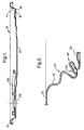
- Figure 3 is a side section of the end of the present invention;
- Figure 4 is the enlarged view of IV in figure 3; and
- Figure 5 is the enlarged view of V in figure 3.
- The easy open can end 10 of figure 1 includes a
seaming panel 12,wall 14 joining theseaming panel 12 to acountersink bead 16 andinner wall 18 of the countersink bead which supports acentre panel 20 of the can end. A line of weakness, typically in the form of a score, extends around thecentre panel 10 near thewall 14 to define a removable panel. - In the easy open end of figure 1, a
pull tab 22 is fixed to anintegral rivet 24 raised from the metal of thecentre panel 20. The tab is raised to break or "pop" the score line and is then pulled progressively to remove the removable panel by tearing the rest of the score line. European patent application EP-98921661.9 describes how selective positioning of the tab with respect to the grain orientation of the metal of the can end reduces tear force requirements without adversely affecting the pop force needed to break the score. Orienting of the can end during manufacture, however, necessitates extra tooling and, possibly, additional tooling stations. Whilst the resultant can end may be more readily opened than conventional easy open ends, the extra capital costs involved may deter some manufacturers. - The enlarged section of figure 2 shows the part of a can end which included
seaming panel 12,centre panel 20 andscore 30. In this can end, however, there is no countersink and the wall 14' is joined to thecentre panel 20 by adouble fold Score 30 is situated inlower fold 34, rather than on the centre panel, and is partially covered byupper fold 32. This means that the aperture obtained on opening the can end is maximised as not onlycentre panel 20, but also most oflower fold 34 is removed. Nonetheless, the abuse resistance of this can end is poor (i.e. when the can is dropped) as distortion of the double fold is transmitted directly through the score, causing score rupture. Furthermore, during processing of product (such as food) within a can which is closed by the end of figure 2, pressure changes within the can may lead to rotation of the tab until it becomes hooked over the seam and risks hook-up on parts of the retort apparatus. - In figure 1, the outer wall of the
countersink 16 is integral with thewall 14. In the can end of the invention, as shown in figures 3 to 5, thewall 14 andouter wall 17 of thecountersink 16, are separated by a flat "stepped"portion 19. Thenose 23 ofpull tab 22 overlies thescore 26 in thecentre panel 20, as in figure 1. - In contrast in particular with the prior art design of figure 2, the provision of a countersink, i.e. radiused
portion 16, gives improved abuse and pressure performance and avoids "tab over seam" hook-up. - A most important aspect of the present invention is that the can end of figure 3 to 5 not only gives better performance than the prior art design of figure 2 and equal pressure resistance to the design of figure 1, but it also offers an alternative opening method to the consumer. Thus, although it is expected that the majority of customers will use the pull tab to break the score and remove the
centre panel 20 in conventional manner, there is an alternative available to those unwilling or unable to use the tab. - Specifically, the "stepped portion" 19 between
wall 14 andouter wall 17 of thecountersink 16 comprises a flat annulus of approximately 4 mm in width (difference between inner and outer diameter). By use of a can opener, the user is able to engage the wheel blade of the can opener on the flat portion and, by progressive cutting of thestepped portion 19 around the whole of the can end, removal of thecentre panel 20 andcountersink 16 is possible. - The height of wall 14 (distance h in figure 4) must be no more than 4 mm or a can opener will be unable to engage the
annulus 19. This height should be from 3 mm to 4 mm, typically about 3.5 mm. - The annulus can be up to 10 mm although clearly the larger the annulus, the smaller the aperture of an end of the same overall diameter will be. Furthermore, a can end having an annulus of much greater than 4 mm may have unacceptable pressure performance. The annulus should be at least 1 mm in width and ideally not be less than 2 mm to allow sufficient width of flat portion for engagement with a can opener.
- By providing a combination of opening methods to the consumer, the applicant has found that the consumer is offered more choice in opening. Furthermore, there is not only no adverse affect on performance but also potential improvements in abuse and pressure performance.
Claims (5)
- A can end (10) comprising a seaming panel (12), a wall (14) depending from the seaming panel and a centre panel (20); in which:the centre panel (20) includes a circumferential score and a tab (22) adjacent the score; and the can end further includes a substantially flat portion (19) extending radially inwardly from the wall (14);such that the can end is adapted for opening either by raising the tab to rupture the score and thereby remove the centre panel, or by engaging the flat portion with a can opener blade and cutting around an annulus defined by the flat portion to remove the radially inward part of the can end;characterised by the height of wall (14) being from 3 to 4 mm; and by a countersink bead (16), the outer wall of the countersink bead being connected to a radially inward edge of the flat portion (19), and the inner wall of the countersink bead supporting the centre panel (20).
- A can end according to claim 1, in which the substantially flat portion (19) is 2 mm or more in width.
- A can end according to claim 1 or claim 2, in which the substantially flat portion is 10 mm or less in width.
- A can end according to any one of claims 1 to 3, in which the substantially flat portion is 4 mm in width.
- A two piece can comprising a can body with integral base, and the can end of any one of claims 1 to 4.
Priority Applications (1)
| Application Number | Priority Date | Filing Date | Title |
|---|---|---|---|
| EP03739439A EP1474338B1 (en) | 2002-02-15 | 2003-01-20 | Can end |
Applications Claiming Priority (4)
| Application Number | Priority Date | Filing Date | Title |
|---|---|---|---|
| EP02251059 | 2002-02-15 | ||
| EP02251059A EP1336570A1 (en) | 2002-02-15 | 2002-02-15 | Can end |
| EP03739439A EP1474338B1 (en) | 2002-02-15 | 2003-01-20 | Can end |
| PCT/EP2003/000521 WO2003068615A1 (en) | 2002-02-15 | 2003-01-20 | Can end |
Publications (2)
| Publication Number | Publication Date |
|---|---|
| EP1474338A1 EP1474338A1 (en) | 2004-11-10 |
| EP1474338B1 true EP1474338B1 (en) | 2007-03-28 |
Family
ID=27619186
Family Applications (2)
| Application Number | Title | Priority Date | Filing Date |
|---|---|---|---|
| EP02251059A Withdrawn EP1336570A1 (en) | 2002-02-15 | 2002-02-15 | Can end |
| EP03739439A Expired - Lifetime EP1474338B1 (en) | 2002-02-15 | 2003-01-20 | Can end |
Family Applications Before (1)
| Application Number | Title | Priority Date | Filing Date |
|---|---|---|---|
| EP02251059A Withdrawn EP1336570A1 (en) | 2002-02-15 | 2002-02-15 | Can end |
Country Status (6)
| Country | Link |
|---|---|
| US (1) | US20050082292A1 (en) |
| EP (2) | EP1336570A1 (en) |
| AT (1) | ATE358059T1 (en) |
| AU (1) | AU2003210171A1 (en) |
| DE (1) | DE60312823T2 (en) |
| WO (1) | WO2003068615A1 (en) |
Families Citing this family (4)
| Publication number | Priority date | Publication date | Assignee | Title |
|---|---|---|---|---|
| ES2568435T3 (en) * | 2007-12-24 | 2016-04-29 | Ardagh Mp Group Netherlands B.V. | Tin can and a method to make such a can |
| EP2157023B1 (en) * | 2008-08-21 | 2014-10-22 | Ardagh MP Group Netherlands B.V. | Lid for a can and method for orientating such a lid |
| US8939308B2 (en) * | 2009-09-04 | 2015-01-27 | Crown Packaging Technology, Inc. | Full aperture beverage end |
| US9714114B2 (en) | 2013-11-08 | 2017-07-25 | Crown Packaging Technology, Inc. | Full aperture can end |
Family Cites Families (4)
| Publication number | Priority date | Publication date | Assignee | Title |
|---|---|---|---|---|
| GB2168672B (en) * | 1984-12-11 | 1989-01-11 | Toyo Seikan Kaisha Ltd | Lid for readily openable can |
| US5169017A (en) * | 1990-09-05 | 1992-12-08 | H. J. Heinz Company | Can end closure apparatus |
| DK173974B1 (en) * | 1996-09-26 | 2002-03-18 | Glud & Marstrand As | Box with lid, which is fitted with a lifting ring |
| US6234337B1 (en) * | 1998-08-14 | 2001-05-22 | H.J. Heinz Company | Safe container end closure and method for fabricating a safe container end closure |
-
2002
- 2002-02-15 EP EP02251059A patent/EP1336570A1/en not_active Withdrawn
-
2003
- 2003-01-20 EP EP03739439A patent/EP1474338B1/en not_active Expired - Lifetime
- 2003-01-20 AT AT03739439T patent/ATE358059T1/en not_active IP Right Cessation
- 2003-01-20 AU AU2003210171A patent/AU2003210171A1/en not_active Abandoned
- 2003-01-20 WO PCT/EP2003/000521 patent/WO2003068615A1/en not_active Ceased
- 2003-01-20 DE DE60312823T patent/DE60312823T2/en not_active Expired - Lifetime
- 2003-01-20 US US10/503,218 patent/US20050082292A1/en not_active Abandoned
Also Published As
| Publication number | Publication date |
|---|---|
| US20050082292A1 (en) | 2005-04-21 |
| WO2003068615A1 (en) | 2003-08-21 |
| DE60312823T2 (en) | 2007-08-16 |
| AU2003210171A1 (en) | 2003-09-04 |
| EP1336570A1 (en) | 2003-08-20 |
| DE60312823D1 (en) | 2007-05-10 |
| ATE358059T1 (en) | 2007-04-15 |
| EP1474338A1 (en) | 2004-11-10 |
Similar Documents
| Publication | Publication Date | Title |
|---|---|---|
| EP2160332B1 (en) | Can end and method of making same | |
| AU620156B2 (en) | Improved easy open can end and method of manufacture thereof | |
| EP0220820B1 (en) | Metal can end with plastics closure | |
| US5816428A (en) | Easy-open can end and spout | |
| CA1225345A (en) | Can end with retained tear strip | |
| EP2081709B1 (en) | Easy open can end with high pressure venting | |
| AU2001273746B2 (en) | Can lid | |
| EP0986500A1 (en) | Can with easy open end | |
| WO1991008143A1 (en) | Container end member | |
| US3796344A (en) | Non-detachable tear strip and pull tab structure for easy opening container | |
| US5950859A (en) | Container with sealing member | |
| WO1998042582A9 (en) | Container with sealing member | |
| US20050082292A1 (en) | Can end | |
| US3715051A (en) | Easy opening container | |
| AU761490B2 (en) | End closure with improved non-detachable opening panel | |
| KR101747986B1 (en) | A panel for a container, a container provided with such container and a method for making same | |
| US3454185A (en) | Easy opening can end | |
| US3172558A (en) | Container with improved easy-open end | |
| EP0090809B1 (en) | Closure for containers | |
| MX2012001906A (en) | Conversion of existing open top container to reclosable can. | |
| US7909555B2 (en) | Tool for making easy open can end with high pressure venting | |
| EP0993347A1 (en) | Tab manufacture | |
| EP0638043A1 (en) | Vacuum container with easy open closure | |
| AU2004222748A1 (en) | Sheet metal containers |
Legal Events
| Date | Code | Title | Description |
|---|---|---|---|
| PUAI | Public reference made under article 153(3) epc to a published international application that has entered the european phase |
Free format text: ORIGINAL CODE: 0009012 |
|
| 17P | Request for examination filed |
Effective date: 20040708 |
|
| AK | Designated contracting states |
Kind code of ref document: A1 Designated state(s): AT BE BG CH CY CZ DE DK EE ES FI FR GB GR HU IE IT LI LU MC NL PT SE SI SK TR |
|
| AX | Request for extension of the european patent |
Extension state: AL LT LV MK RO |
|
| 17Q | First examination report despatched |
Effective date: 20050405 |
|
| GRAP | Despatch of communication of intention to grant a patent |
Free format text: ORIGINAL CODE: EPIDOSNIGR1 |
|
| GRAS | Grant fee paid |
Free format text: ORIGINAL CODE: EPIDOSNIGR3 |
|
| GRAA | (expected) grant |
Free format text: ORIGINAL CODE: 0009210 |
|
| AK | Designated contracting states |
Kind code of ref document: B1 Designated state(s): AT BE BG CH CY CZ DE DK EE ES FI FR GB GR HU IE IT LI LU MC NL PT SE SI SK TR |
|
| PG25 | Lapsed in a contracting state [announced via postgrant information from national office to epo] |
Ref country code: AT Free format text: LAPSE BECAUSE OF FAILURE TO SUBMIT A TRANSLATION OF THE DESCRIPTION OR TO PAY THE FEE WITHIN THE PRESCRIBED TIME-LIMIT Effective date: 20070328 Ref country code: CH Free format text: LAPSE BECAUSE OF FAILURE TO SUBMIT A TRANSLATION OF THE DESCRIPTION OR TO PAY THE FEE WITHIN THE PRESCRIBED TIME-LIMIT Effective date: 20070328 Ref country code: SI Free format text: LAPSE BECAUSE OF FAILURE TO SUBMIT A TRANSLATION OF THE DESCRIPTION OR TO PAY THE FEE WITHIN THE PRESCRIBED TIME-LIMIT Effective date: 20070328 Ref country code: LI Free format text: LAPSE BECAUSE OF FAILURE TO SUBMIT A TRANSLATION OF THE DESCRIPTION OR TO PAY THE FEE WITHIN THE PRESCRIBED TIME-LIMIT Effective date: 20070328 Ref country code: FI Free format text: LAPSE BECAUSE OF FAILURE TO SUBMIT A TRANSLATION OF THE DESCRIPTION OR TO PAY THE FEE WITHIN THE PRESCRIBED TIME-LIMIT Effective date: 20070328 |
|
| REG | Reference to a national code |
Ref country code: GB Ref legal event code: FG4D |
|
| REG | Reference to a national code |
Ref country code: CH Ref legal event code: EP |
|
| REF | Corresponds to: |
Ref document number: 60312823 Country of ref document: DE Date of ref document: 20070510 Kind code of ref document: P |
|
| REG | Reference to a national code |
Ref country code: IE Ref legal event code: FG4D |
|
| PG25 | Lapsed in a contracting state [announced via postgrant information from national office to epo] |
Ref country code: SE Free format text: LAPSE BECAUSE OF FAILURE TO SUBMIT A TRANSLATION OF THE DESCRIPTION OR TO PAY THE FEE WITHIN THE PRESCRIBED TIME-LIMIT Effective date: 20070628 |
|
| PG25 | Lapsed in a contracting state [announced via postgrant information from national office to epo] |
Ref country code: ES Free format text: LAPSE BECAUSE OF FAILURE TO SUBMIT A TRANSLATION OF THE DESCRIPTION OR TO PAY THE FEE WITHIN THE PRESCRIBED TIME-LIMIT Effective date: 20070709 |
|
| PG25 | Lapsed in a contracting state [announced via postgrant information from national office to epo] |
Ref country code: PT Free format text: LAPSE BECAUSE OF FAILURE TO SUBMIT A TRANSLATION OF THE DESCRIPTION OR TO PAY THE FEE WITHIN THE PRESCRIBED TIME-LIMIT Effective date: 20070828 |
|
| ET | Fr: translation filed | ||
| REG | Reference to a national code |
Ref country code: CH Ref legal event code: PL |
|
| PG25 | Lapsed in a contracting state [announced via postgrant information from national office to epo] |
Ref country code: SK Free format text: LAPSE BECAUSE OF FAILURE TO SUBMIT A TRANSLATION OF THE DESCRIPTION OR TO PAY THE FEE WITHIN THE PRESCRIBED TIME-LIMIT Effective date: 20070328 |
|
| PG25 | Lapsed in a contracting state [announced via postgrant information from national office to epo] |
Ref country code: CZ Free format text: LAPSE BECAUSE OF FAILURE TO SUBMIT A TRANSLATION OF THE DESCRIPTION OR TO PAY THE FEE WITHIN THE PRESCRIBED TIME-LIMIT Effective date: 20070328 |
|
| PG25 | Lapsed in a contracting state [announced via postgrant information from national office to epo] |
Ref country code: DK Free format text: LAPSE BECAUSE OF FAILURE TO SUBMIT A TRANSLATION OF THE DESCRIPTION OR TO PAY THE FEE WITHIN THE PRESCRIBED TIME-LIMIT Effective date: 20070328 |
|
| PLBE | No opposition filed within time limit |
Free format text: ORIGINAL CODE: 0009261 |
|
| STAA | Information on the status of an ep patent application or granted ep patent |
Free format text: STATUS: NO OPPOSITION FILED WITHIN TIME LIMIT |
|
| 26N | No opposition filed |
Effective date: 20080102 |
|
| PG25 | Lapsed in a contracting state [announced via postgrant information from national office to epo] |
Ref country code: GR Free format text: LAPSE BECAUSE OF FAILURE TO SUBMIT A TRANSLATION OF THE DESCRIPTION OR TO PAY THE FEE WITHIN THE PRESCRIBED TIME-LIMIT Effective date: 20070629 |
|
| PG25 | Lapsed in a contracting state [announced via postgrant information from national office to epo] |
Ref country code: MC Free format text: LAPSE BECAUSE OF NON-PAYMENT OF DUE FEES Effective date: 20080131 |
|
| PG25 | Lapsed in a contracting state [announced via postgrant information from national office to epo] |
Ref country code: IE Free format text: LAPSE BECAUSE OF NON-PAYMENT OF DUE FEES Effective date: 20080121 Ref country code: EE Free format text: LAPSE BECAUSE OF FAILURE TO SUBMIT A TRANSLATION OF THE DESCRIPTION OR TO PAY THE FEE WITHIN THE PRESCRIBED TIME-LIMIT Effective date: 20070328 |
|
| PG25 | Lapsed in a contracting state [announced via postgrant information from national office to epo] |
Ref country code: CY Free format text: LAPSE BECAUSE OF FAILURE TO SUBMIT A TRANSLATION OF THE DESCRIPTION OR TO PAY THE FEE WITHIN THE PRESCRIBED TIME-LIMIT Effective date: 20070328 |
|
| PG25 | Lapsed in a contracting state [announced via postgrant information from national office to epo] |
Ref country code: BG Free format text: LAPSE BECAUSE OF FAILURE TO SUBMIT A TRANSLATION OF THE DESCRIPTION OR TO PAY THE FEE WITHIN THE PRESCRIBED TIME-LIMIT Effective date: 20070628 |
|
| PG25 | Lapsed in a contracting state [announced via postgrant information from national office to epo] |
Ref country code: LU Free format text: LAPSE BECAUSE OF NON-PAYMENT OF DUE FEES Effective date: 20080120 Ref country code: HU Free format text: LAPSE BECAUSE OF FAILURE TO SUBMIT A TRANSLATION OF THE DESCRIPTION OR TO PAY THE FEE WITHIN THE PRESCRIBED TIME-LIMIT Effective date: 20070929 |
|
| PG25 | Lapsed in a contracting state [announced via postgrant information from national office to epo] |
Ref country code: TR Free format text: LAPSE BECAUSE OF FAILURE TO SUBMIT A TRANSLATION OF THE DESCRIPTION OR TO PAY THE FEE WITHIN THE PRESCRIBED TIME-LIMIT Effective date: 20070328 |
|
| PGFP | Annual fee paid to national office [announced via postgrant information from national office to epo] |
Ref country code: DE Payment date: 20110121 Year of fee payment: 9 Ref country code: IT Payment date: 20110127 Year of fee payment: 9 Ref country code: NL Payment date: 20110117 Year of fee payment: 9 Ref country code: FR Payment date: 20110202 Year of fee payment: 9 |
|
| PGFP | Annual fee paid to national office [announced via postgrant information from national office to epo] |
Ref country code: BE Payment date: 20110104 Year of fee payment: 9 |
|
| PGFP | Annual fee paid to national office [announced via postgrant information from national office to epo] |
Ref country code: GB Payment date: 20110120 Year of fee payment: 9 |
|
| BERE | Be: lapsed |
Owner name: CROWN PACKAGING TECHNOLOGY INC Effective date: 20120131 |
|
| REG | Reference to a national code |
Ref country code: NL Ref legal event code: V1 Effective date: 20120801 |
|
| GBPC | Gb: european patent ceased through non-payment of renewal fee |
Effective date: 20120120 |
|
| REG | Reference to a national code |
Ref country code: DE Ref legal event code: R082 Ref document number: 60312823 Country of ref document: DE Representative=s name: RAINER CALLIES, DE Ref country code: DE Ref legal event code: R082 Ref document number: 60312823 Country of ref document: DE Representative=s name: CALLIES, RAINER, DIPL.-PHYS. DR.RER.NAT., DE |
|
| REG | Reference to a national code |
Ref country code: FR Ref legal event code: ST Effective date: 20120928 |
|
| PG25 | Lapsed in a contracting state [announced via postgrant information from national office to epo] |
Ref country code: GB Free format text: LAPSE BECAUSE OF NON-PAYMENT OF DUE FEES Effective date: 20120120 Ref country code: DE Free format text: LAPSE BECAUSE OF NON-PAYMENT OF DUE FEES Effective date: 20120801 |
|
| REG | Reference to a national code |
Ref country code: DE Ref legal event code: R119 Ref document number: 60312823 Country of ref document: DE Effective date: 20120801 |
|
| PG25 | Lapsed in a contracting state [announced via postgrant information from national office to epo] |
Ref country code: IT Free format text: LAPSE BECAUSE OF NON-PAYMENT OF DUE FEES Effective date: 20120120 |
|
| PG25 | Lapsed in a contracting state [announced via postgrant information from national office to epo] |
Ref country code: BE Free format text: LAPSE BECAUSE OF NON-PAYMENT OF DUE FEES Effective date: 20120131 Ref country code: FR Free format text: LAPSE BECAUSE OF NON-PAYMENT OF DUE FEES Effective date: 20120131 |
|
| PG25 | Lapsed in a contracting state [announced via postgrant information from national office to epo] |
Ref country code: NL Free format text: LAPSE BECAUSE OF NON-PAYMENT OF DUE FEES Effective date: 20120801 |