EP1473936A1 - Système de distribution de signaux de télévision et procédé le mettant en oeuvre - Google Patents
Système de distribution de signaux de télévision et procédé le mettant en oeuvre Download PDFInfo
- Publication number
- EP1473936A1 EP1473936A1 EP04291096A EP04291096A EP1473936A1 EP 1473936 A1 EP1473936 A1 EP 1473936A1 EP 04291096 A EP04291096 A EP 04291096A EP 04291096 A EP04291096 A EP 04291096A EP 1473936 A1 EP1473936 A1 EP 1473936A1
- Authority
- EP
- European Patent Office
- Prior art keywords
- terminal
- inverter
- slope
- attenuator
- mhz
- Prior art date
- Legal status (The legal status is an assumption and is not a legal conclusion. Google has not performed a legal analysis and makes no representation as to the accuracy of the status listed.)
- Granted
Links
- 238000000034 method Methods 0.000 title claims abstract description 6
- 239000004020 conductor Substances 0.000 claims abstract description 18
- 230000003321 amplification Effects 0.000 claims abstract description 16
- 238000003199 nucleic acid amplification method Methods 0.000 claims abstract description 16
- 238000009434 installation Methods 0.000 description 7
- 238000012550 audit Methods 0.000 description 4
- 230000003313 weakening effect Effects 0.000 description 3
- 230000005540 biological transmission Effects 0.000 description 2
- 239000006185 dispersion Substances 0.000 description 2
- 240000008042 Zea mays Species 0.000 description 1
- 230000008602 contraction Effects 0.000 description 1
- 235000021183 entrée Nutrition 0.000 description 1
- 239000000463 material Substances 0.000 description 1
- 238000005259 measurement Methods 0.000 description 1
Images

Classifications
-
- A—HUMAN NECESSITIES
- A01—AGRICULTURE; FORESTRY; ANIMAL HUSBANDRY; HUNTING; TRAPPING; FISHING
- A01B—SOIL WORKING IN AGRICULTURE OR FORESTRY; PARTS, DETAILS, OR ACCESSORIES OF AGRICULTURAL MACHINES OR IMPLEMENTS, IN GENERAL
- A01B1/00—Hand tools
- A01B1/02—Spades; Shovels
- A01B1/022—Collapsible; extensible; combinations with other tools
-
- H—ELECTRICITY
- H04—ELECTRIC COMMUNICATION TECHNIQUE
- H04N—PICTORIAL COMMUNICATION, e.g. TELEVISION
- H04N7/00—Television systems
- H04N7/10—Adaptations for transmission by electrical cable
- H04N7/108—Adaptations for transmission by electrical cable the cable being constituted by a pair of wires
-
- A—HUMAN NECESSITIES
- A01—AGRICULTURE; FORESTRY; ANIMAL HUSBANDRY; HUNTING; TRAPPING; FISHING
- A01C—PLANTING; SOWING; FERTILISING
- A01C7/00—Sowing
- A01C7/02—Hand sowing implements
-
- A—HUMAN NECESSITIES
- A01—AGRICULTURE; FORESTRY; ANIMAL HUSBANDRY; HUNTING; TRAPPING; FISHING
- A01G—HORTICULTURE; CULTIVATION OF VEGETABLES, FLOWERS, RICE, FRUIT, VINES, HOPS OR SEAWEED; FORESTRY; WATERING
- A01G5/00—Floral handling
- A01G5/02—Apparatus for binding bouquets or wreaths
Definitions
- the invention relates to the distribution of television signals.
- the invention aims to enable such distribution to be carried out with a pair of twisted conductors, the length of which can vary over a wide range.
- a signal distribution system for television comprising a first connection terminal, adapted to receive a coaxial cable for television signal distribution, and at least a second connection terminal, suitable for receiving a pair of twisted conductors, characterized in that it comprises an amplification assembly provided with a selection between a first slope and a second growth slope, in function of the frequency, of the gain between the signal present on said first terminal and the signal present on said second terminal.
- the possibility of selecting one or the other amplification slope allows to best adjust the processing performed in the amplification assembly to the length of the twisted pair of conductors, and consequently allows distribute television signals longer than the limits conventionally accepted today, which are around 30 m.
- said set of amplification includes a linear amplifier, one input of which is connected to said first terminal, a positive slope attenuator, one input of which is connected to the output of said terminal amplifier, and a signal shaper having an input connected to the output of said amplifier positive slope attenuator and an output connected to said second terminal, with said conformator which is adapted to selectively insert a slope attenuator negative between its said entry and its said exit.
- the invention also relates, in a second aspect, to a method distribution of television signals, characterized in that it comprises the step of providing a system as set out above, the step of determining a threshold length of said twisted pair of conductors, and the step of selecting said first slope when the twisted pair has a length less than said threshold and said second slope when the twisted pair has a length greater than said threshold.
- said threshold is between 27 and 29 m.
- the installation 8 illustrated diagrammatically in FIG. 1 comprises a system 9 provided with a connection terminal 10 to which a coaxial cable 11 terminates and provided with eight connection terminals 12A to 12H to each of which leads to a respective of eight pairs of twisted conductors 13A to 13H, which are each connected, at the opposite end to the system 9, to a socket 14.
- the system 9 is here arranged in a technical sheath of the building residential or tertiary to which the installation belongs 8.
- Cable 11 is connected to a receiving antenna or to a cable network for the distribution of terrestrial television signals.
- the pairs of twisted conductors 13A to 13H are here each part a conventional local computer network cable.
- Each of these cables comprises, in addition to one of the pairs 13A to 13H, three other pairs of twisted conductors carrying signals of another kind, in this case local computer network signals and telephony signals.
- These cables run in the aforementioned building between system 9, which is part of a more complete set of signal distribution, and one of the sockets 14.
- Each of the sockets 14 is here of the RJ 45 type, in category 6.
- Each pairs 13A to 13H is connected, on the corresponding socket 14, to the pair of contacts conventionally called "7" and "8".
- a adapter plugged into this socket 14 and a coaxial cable plugged between the adapter and the television set.
- the coaxial cable and the adapter are combined in a single cord.
- This adapter is used to convert the balanced signal present on the pair of conductors twisted into an asymmetrical signal conveyable on a coaxial cable.
- the system 9 comprises a linear amplifier 15, an attenuator 16 to positive slope, an eight-way distributor 17 and eight signal conformers 18.
- the input of amplifier 15 is connected to terminal 10.
- the output of amplifier 15 is connected to the input of attenuator 16.
- the output of the attenuator 16 is connected to the input of the distributor 17.
- Each of the eight outputs of the distributor 17 is connected to the input of one conformers 18.
- each conformator 18 is connected to one of the terminals 12A to 12H.
- the signal television retains its conventional asymmetrical shape.
- the conformers 18 are identical. We will now describe one of them in more detail in support of Figure 2.
- Shaper 18 includes an inverter 19, an attenuator 20 to negative slope, an inverter 21, a switch 22 for controlling the inverters 19 and 21 and a converter 23 from asymmetric signal to symmetrical signal.
- the inverter 19 has three terminals, respectively 24, 25 and 26. In the position illustrated in Figure 2, the inverter 19 connects the terminals 24 and 26 while it isolates terminals 24 and 25 from one another. The inverter 19 admits another position or it connects terminals 24 and 25 while it isolates terminals 24 and 26 from each other.
- the inverter 21 has three terminals 27, 28 and 29.
- the inverter 21 connects the terminals 27 and 28 while it insulates terminals 27 and 29 from each other. In its other position, the inverter 21 connects the terminals 27 and 29 while it isolates the terminals 27 from one another and 28.
- Terminal 25 of inverter 19 and terminal 29 of inverter 21 are connected to each other.
- Terminal 26 is connected to the input of the attenuator 20.
- Terminal 28 is connected to the output of the attenuator 20.
- Terminal 27 is connected to the input of converter 23.
- the switch 22 has a cursor 30 with three positions, identified by 0, I and II respectively.
- the inverters 19 and 21 are controlled to each take the position other than that illustrated in FIG. 2, namely that the inverter 19 connects the terminals 24 and 25 while it isolates the terminals 24 from one another and 26 and that the switch 21 connects the terminals 27 and 29 while it isolates one of the other, terminals 27 and 28.
- the inverters 19 and 21 are controlled so that one of them adopts the position other than that illustrated in FIG. 2 and so that the other keeps this position, for example so that the inverter 19 connects the terminals 24 and 25 while it isolates terminals 24 and 26 from each other while the inverter 21 keep the position illustrated in figure 2.
- the shaper 18 In position I of the cursor 30, the shaper 18 is in the position illustrated in FIG. 2, where the signal present at the input of the unit 18 passes through of the attenuator 20 then of the converter 23.
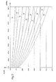
- the graph which forms figure 3 illustrates the weakening of a signal of terrestrial television during its propagation in one of the pairs 13A to 13H, following frequencies.
- the curves 31 to 40 correspond to a length respectively of 5, 10, 15, 20, 25, 30, 35, 40, 45 and 50 meters for the length of the twisted pair in question.
- the difference between the 47 MHz loss and the 862 MHz loss is thus 3.3 dB for a length of 5 m and 25.2 dB for a length of 50 m.
- system 9 is configurable for each of the pairs 13A to 13H so that the amplification to be carried out between the cable 11 and the twisted pair in question can be carried out according to a gain increasing as a function of frequency selectively with one of two slopes separate, depending on whether the length of the pair in question is less or greater than a predetermined threshold.
- the cursor 30 of switch 22 is placed in position I while that if the length of this pair is greater than 28 m, the cursor 30 is placed on position II.
- the linear amplifier 15 is followed by the only attenuator 16.
- the amplifier 15 which is linear in the sense that it provides the same gain over the entire frequency band of the signal terrestrial television (from 5 to 862 MHz), has a gain of 18.4 dB while, as illustrated very schematically in Figure 1, the slope of the attenuator 16 is such that there is a loss of 22 dB at 47 MHz and no loss at 862 MHz.
- the assembly formed by the amplifier 15 and by the attenuator 16 provides thus a gain increasing regularly from -3.6 dB at 47 MHz to +18.4 dB at 862 MHz.
- the attenuation provided by the attenuator 20 is zero at 47 MHz and gradually increases until the value of 14 dB at the frequency of 862 MHz.
- the overall gain provided by the amplifier 15, by the attenuator 16 and by the attenuator 20, i.e. the overall gain of the system 9 between its input and one of the twisted pairs 13A to 13H when the cursor 30 of unit 18 is in the position I, is therefore -3.6 dB at 47 MHz and +4.4 dB at 862 MHz.
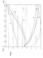
- the curves 41 to 44 correspond to a twisted pair length of 5 m, 18 m, 26 m and 27.9 respectively m.
- Curves 45 to 48 correspond to a length 28.1 m, 30 m, 38 m and 50 m respectively. Each of these lengths being greater than the threshold of 28 m, the cursor 30 is in position II.
- 862 MHz does not should not be considered as an upper limit beyond which the transmission of television signals is no longer possible, and on the contrary a such transmission is possible, if desired, for example up to 900 or 950 MHz or even beyond.
- the conformator 18 if it constitutes a set functional, does not necessarily constitute a one-piece material element, and even for system 9.
- the amplifier 15, the attenuator 16, the distributor 17 and the portion of each conformator 18 located between terminals 24 and 27 are combined in an active electronic unit, while the converter 23 and the terminals 10 as well as 12A to 12H are part of a cable concentrator provided with a connector to receive this unit active electronics.
- the switch 22 with manual slider 30 is replaced by an automated configuration device comprising means for measuring the length of the twisted pair, for example by resistivity or by reflection of a wave, and a switch controlled by this measuring member for automatically take position I or position II depending on whether the result of the link length measurement is less than or greater than the threshold.
- the amplifier 15 and the attenuator 16 common to each of the pairs 13A to 13H and the attenuator 20 specific to one of the pairs in question are replaced by individual sets of amplification to selectable slopes each disposed in one of the conformers 18.
- each amplification assembly specific to one of the twisted pairs has more than two slopes of growth, as a function of frequency, of the gain between the signal present on the terminal such as 10 and the signal present on the terminal such as 12A to 12H in question, so for example to be able to broadcast television signals on a twisted pair having a length greater than the threshold of 50m; and / or each twisted pair exhibits different signal weakening characteristics those illustrated in FIG. 3, in particular improved performance corresponding to curves similar to curves 31 to 40 but with the axis of abscissa which is contracted, i.e. with the numerical values appearing in Figure 3 which are replaced by larger numeric values.
Landscapes
- Life Sciences & Earth Sciences (AREA)
- Engineering & Computer Science (AREA)
- Soil Sciences (AREA)
- Environmental Sciences (AREA)
- Multimedia (AREA)
- Signal Processing (AREA)
- Mechanical Engineering (AREA)
- Details Of Television Systems (AREA)
- Cable Transmission Systems, Equalization Of Radio And Reduction Of Echo (AREA)
- Communication Cables (AREA)
- Two-Way Televisions, Distribution Of Moving Picture Or The Like (AREA)
Abstract
Description
- ledit conformateur comporte :
- un premier inverseur, présentant une première borne, une deuxième borne et une troisième borne, admettant une première position où il relie ladite première borne à ladite troisième borne tandis qu'il isole l'une de l'autre ladite première borne et ladite deuxième borne, et admettant une deuxième position où il relie ladite première borne à ladite deuxième borne tandis qu'il isole l'une de l'autre ladite première borne et ladite troisième borne, avec la troisième borne qui est reliée audit atténuateur à pente positive ;
- un deuxième inverseur, présentant une première borne, une deuxième borne et une troisième borne, admettant une première position où il relie la première borne et la deuxième borne tandis qu'il isole la première borne et la troisième borne, et admettant une deuxième position où il relie la première borne et la troisième borne tandis qu'il isole l'une de l'autre la première borne et la deuxième borne, avec la deuxième borne du deuxième inverseur qui est reliée audit atténuateur à pente négative et avec ladite troisième borne du deuxième inverseur qui est reliée à la deuxième borne du premier inverseur ; et
- un organe de pilotage dudit premier inverseur et dudit deuxième inverseur, adapté à mettre le premier inverseur et le deuxième inverseur sélectivement chacun dans sa première position et chacun dans sa deuxième position ; et éventuellement
- ledit organe est également adapté à faire prendre audit premier inverseur et audit deuxième inverseur respectivement l'une desdites première et deuxième positions et l'autre desdites première et deuxième positions ; et/ou
- ledit organe de configuration comporte un bouton de commande manuelle.
- ledit atténuateur à pente positive présente un gain dont l'écart entre sa valeur à 47 MHz et sa valeur à 862 MHz est compris entre 21 et 23 dB ; et éventuellement
- ledit atténuateur à pente négative dudit conformateur présente un gain dont l'écart entre sa valeur à 47 MHz et sa valeur à 862 MHz est compris entre 13 et 15 dB ; et/ou
- le gain dudit amplificateur linéaire est compris entre 17,4 et 19,4 dB.
- le système selon l'invention comporte plusieurs deuxièmes bornes de connexion avec ledit ensemble d'amplification qui est muni d'un dit conformateur de signal pour chaque dite deuxième borne ; et éventuellement
- le système selon l'invention comporte un répartiteur présentant une entrée reliée à la sortie dudit atténuateur à pente positive et présentant des sorties reliées chacune à un dit conformateur de signal respectif.
- ledit système comporte plusieurs deuxièmes bornes de connexion avec ledit ensemble d'amplification qui est muni d'un dit organe de sélection pour chaque dite deuxième borne ; et/ou
- ledit conformateur comporte un convertisseur de signal asymétrique en signal symétrique.
- la figure 1 est une représentation schématique d'une installation de distribution de signaux de télévision comportant une système conforme à l'invention ;
- la figure 2 est une représentation schématique donnant le détail de l'un des conformateurs de signal que comporte ce système entre un répartiteur et une borne de connexion à une paire de conducteurs torsadée ;
- la figure 3 est un graphe illustrant l'affaiblissement des signaux de télévision terrestre lors de leur propagation dans une paire de conducteurs torsadée, ce graphe portant en abscisses les fréquences, exprimées en MHz, portant en ordonnée le gain, exprimé en dB, et donnant une série de courbes pour différentes longueurs de paires de conducteurs torsadées ; et
- la figure 4 est un graphe similaire, mais pour la propagation dans l'ensemble de l'installation illustrée sur la figure 1, avec l'axe des ordonnées qui est dilaté par rapport à celui de la figure 3.
- pour l'atténuateur 16, un gain dont l'écart entre sa valeur à 47 MHz et sa valeur à 862 MHz est compris entre 21 et 23 dB ;
- pour l'atténuateur 20, un gain dont l'écart entre sa valeur à 47 MHz et sa valeur à 862 MHz est compris entre 13 et 15 dB ;
- pour l'amplificateur linéaire 15, un gain compris entre 17,4 et 19,4 dB ; et
- pour la longueur des paires torsadées, un seuil compris entre 27 et 29 m, et plus précisément l'emploi de la pente à petite amplitude pour des longueurs comprises entre 5 m et ce seuil et l'emploi de la pente à grande amplitude pour des longueurs comprises entre le seuil et 50 m.
Claims (15)
- Système de distribution de signaux de télévision, comportant une première borne de connexion (10), adaptée à recevoir un câble coaxial (11) de distribution de signaux de télévision, et au moins une deuxième borne de connexion (12A-12H), adaptée à recevoir une paire (13A-13H) de conducteurs torsadée, caractérisé en ce qu'il comporte un ensemble d'amplification (15, 16, 18) muni d'un organe (22) de sélection entre une première pente et une deuxième pente de croissance, en fonction de la fréquence, du gain entre le signal présent sur ladite première borne (10) et le signal présent sur ladite deuxième borne (12A-12H).
- Système selon la revendication 1, caractérisé en ce que ledit ensemble d'amplification comporte un amplificateur linéaire (15) dont une entrée est reliée à ladite première borne (10), un atténuateur à pente positive (16) dont une entrée est reliée à la sortie dudit amplificateur (15), et un conformateur de signal (18) ayant une entrée reliée à la sortie dudit atténuateur à pente positive (16) et une sortie reliée à ladite deuxième borne (12A-12H), avec ledit conformateur (18) qui est adapté à insérer sélectivement un atténuateur (20) à pente négative entre sa dite entrée et sa dite sortie.
- Système selon la revendication 2, caractérisé en ce que ledit conformateur (18) comporte :un premier inverseur (19), présentant une première borne (24), une deuxième borne (25) et une troisième borne (26), admettant une première position où il relie ladite première borne (24) à ladite troisième borne (26) tandis qu'il isole l'une de l'autre ladite première borne (24) et ladite deuxième borne (25), et admettant une deuxième position où il relie ladite première borne (24) à ladite deuxième borne (25) tandis qu'il isole l'une de l'autre ladite première borne (24) et ladite troisième borne (26), avec la troisième borne (26) qui est reliée audit atténuateur à pente positive (20) ;un deuxième inverseur (21), présentant une première borne (27), une deuxième borne (28) et une troisième borne (29), admettant une première position où il relie la première borne (27) et la deuxième borne (28) tandis qu'il isole la première borne (27) et la troisième borne (29), et admettant une deuxième position où il relie la première borne (27) et la troisième borne (29) tandis qu'il isole l'une de l'autre la première borne (27) et la deuxième borne (28), avec la deuxième borne (28) du deuxième inverseur (21) qui est reliée audit atténuateur à pente négative (20) et avec ladite troisième borne (29) du deuxième inverseur (21) qui est reliée à la deuxième borne (25) du premier inverseur (19) ; etun organe (22) de pilotage dudit premier inverseur (19) et dudit deuxième inverseur (21), adapté à mettre le premier inverseur et le deuxième inverseur sélectivement chacun dans sa première position et chacun dans sa deuxième position.
- Système selon la revendication 3, caractérisé en ce que ledit organe (22) est également adapté à faire prendre audit premier inverseur (19) et audit deuxième inverseur (21) respectivement l'une desdites première et deuxième positions et l'autre desdites première et deuxième positions.
- Système selon l'une quelconque des revendications 3 ou 4, caractérisé en ce que ledit organe de configuration (22) comporte un bouton (30) de commande manuelle.
- Système selon l'une quelconque des revendications 2 à 5, caractérisé en ce que ledit atténuateur (16) à pente positive présente un gain dont l'écart entre sa valeur à 47 MHz et sa valeur à 862 MHz est compris entre 21 et 23 dB.
- Système selon la revendication 6, caractérisé en ce que ledit atténuateur à pente négative (20) dudit conformateur (18) présente un gain dont l'écart entre sa valeur à 47 MHz et sa valeur à 862 MHz est compris entre 13 et 15 dB.
- Système selon l'une quelconque des revendications 6 ou 7, caractérisé en ce que le gain dudit amplificateur linéaire (15) est compris entre 17,4 et 19,4 dB.
- Système selon l'une quelconque des revendications 2 à 8, caractérisé en ce qu'il comporte plusieurs deuxièmes bornes de connexion (12A-12H) avec ledit ensemble d'amplification (15, 16, 18) qui est muni d'un dit conformateur de signal (18) pour chaque dite deuxième borne (12A-12H).
- Système selon la revendication 9, caractérisé en ce qu'il comporte un répartiteur (17) présentant une entrée reliée à la sortie dudit atténuateur à pente positive (16) et présentant des sorties reliées chacune à un dit conformateur de signal respectif (18).
- Système selon l'une quelconque des revendications 1 à 10, caractérisé en ce qu'il comporte plusieurs deuxièmes bornes de connexion (12A-12H) avec ledit ensemble d'amplification (15, 16, 18) qui est muni d'un dit organe de sélection (22) pour chaque dite deuxième borne (12A-12H).
- Système selon l'une quelconque des revendications 1 à 11, caractérisé en ce que chaque dit conformateur (18) comporte un convertisseur (23) de signal asymétrique en signal symétrique.
- Procédé de distribution de signaux de télévision, caractérisé en ce qu'il comporte l'étape de se procurer un système selon l'une quelconque des revendications 1 à 12, l'étape de déterminer un seuil de longueur de ladite paire de conducteurs torsadée (13A-13H), et l'étape de sélectionner ladite première pente lorsque la paire torsadée (13A-13H) a une longueur inférieure audit seuil et ladite deuxième pente lorsque la paire torsadée (13A-13H) a une longueur supérieure audit seuil.
- Procédé selon la revendication 13, caractérisé en ce que ledit seuil est compris entre 27 et 29 m.
- Procédé selon l'une quelconque des revendications 13 ou 14, caractérisé en ce que ladite étape de sélectionner comporte la sélection de ladite première pente lorsque la paire torsadée (13A-13H) a une longueur comprise entre 5m et ledit seuil et comporte la sélection de ladite deuxième pente lorsque ladite paire torsadée (13A-13H) a une longueur comprise entre ledit seuil et 50m.
Applications Claiming Priority (2)
| Application Number | Priority Date | Filing Date | Title |
|---|---|---|---|
| FR0305335 | 2003-04-30 | ||
| FR0305335A FR2854513B1 (fr) | 2003-04-30 | 2003-04-30 | Systeme de distribution de signaux de television et procede le mettant en oeuvre |
Publications (2)
| Publication Number | Publication Date |
|---|---|
| EP1473936A1 true EP1473936A1 (fr) | 2004-11-03 |
| EP1473936B1 EP1473936B1 (fr) | 2012-01-11 |
Family
ID=32982340
Family Applications (1)
| Application Number | Title | Priority Date | Filing Date |
|---|---|---|---|
| EP04291096A Expired - Lifetime EP1473936B1 (fr) | 2003-04-30 | 2004-04-28 | Système de distribution de signaux de télévision et procédé le mettant en oeuvre |
Country Status (4)
| Country | Link |
|---|---|
| US (1) | US7721319B2 (fr) |
| EP (1) | EP1473936B1 (fr) |
| KR (1) | KR101072840B1 (fr) |
| FR (1) | FR2854513B1 (fr) |
Citations (5)
| Publication number | Priority date | Publication date | Assignee | Title |
|---|---|---|---|---|
| US5305350A (en) * | 1990-06-08 | 1994-04-19 | Chipcom Corporation | Multimedia high speed network |
| WO1997001931A1 (fr) * | 1995-06-28 | 1997-01-16 | The Whitaker Corporation | Systeme de repartition des signaux en bande large |
| WO1998010590A1 (fr) * | 1996-09-02 | 1998-03-12 | Sony Corporation | Dispositif et procede de transmission d'un signal video |
| WO1999067880A1 (fr) * | 1998-06-22 | 1999-12-29 | Rafael Elul | Transmission electrique et emission de signaux via des cables coaxiaux, des cables a paire torsadee et d'autres cables electriques |
| US20030046706A1 (en) * | 2001-08-29 | 2003-03-06 | Rakib Selim Shlomo | Active cable modem outside customer premises servicing multiple customer premises |
Family Cites Families (1)
| Publication number | Priority date | Publication date | Assignee | Title |
|---|---|---|---|---|
| FR2830156B1 (fr) | 2001-09-25 | 2004-11-26 | Henri Lee | Systeme de distribution tv et unite de traitement utilisee dans ce systeme de distribution |
-
2003
- 2003-04-30 FR FR0305335A patent/FR2854513B1/fr not_active Expired - Fee Related
-
2004
- 2004-04-28 KR KR1020040029507A patent/KR101072840B1/ko not_active Expired - Fee Related
- 2004-04-28 EP EP04291096A patent/EP1473936B1/fr not_active Expired - Lifetime
- 2004-04-30 US US10/835,612 patent/US7721319B2/en not_active Expired - Fee Related
Patent Citations (6)
| Publication number | Priority date | Publication date | Assignee | Title |
|---|---|---|---|---|
| US5305350A (en) * | 1990-06-08 | 1994-04-19 | Chipcom Corporation | Multimedia high speed network |
| WO1997001931A1 (fr) * | 1995-06-28 | 1997-01-16 | The Whitaker Corporation | Systeme de repartition des signaux en bande large |
| WO1998010590A1 (fr) * | 1996-09-02 | 1998-03-12 | Sony Corporation | Dispositif et procede de transmission d'un signal video |
| US6567988B1 (en) * | 1996-09-02 | 2003-05-20 | Sony Corporation | Video signal transmission apparatus and video signal transmission method |
| WO1999067880A1 (fr) * | 1998-06-22 | 1999-12-29 | Rafael Elul | Transmission electrique et emission de signaux via des cables coaxiaux, des cables a paire torsadee et d'autres cables electriques |
| US20030046706A1 (en) * | 2001-08-29 | 2003-03-06 | Rakib Selim Shlomo | Active cable modem outside customer premises servicing multiple customer premises |
Also Published As
| Publication number | Publication date |
|---|---|
| KR101072840B1 (ko) | 2011-10-14 |
| FR2854513B1 (fr) | 2006-12-22 |
| US7721319B2 (en) | 2010-05-18 |
| US20050081250A1 (en) | 2005-04-14 |
| EP1473936B1 (fr) | 2012-01-11 |
| KR20040094337A (ko) | 2004-11-09 |
| FR2854513A1 (fr) | 2004-11-05 |
Similar Documents
| Publication | Publication Date | Title |
|---|---|---|
| FR2723170A1 (fr) | Detecteur et procede de detection de defauts pour des tuyaux en metal | |
| FR2699352A1 (fr) | Ensemble et procédé de surveillance d'un système de transmissions optiques. | |
| FR2675579A1 (fr) | Detecteur de defauts pour un materiau metallique, notamment une canalisation, et capteur de courants de foucault a champ distant destine a ce detecteur. | |
| FR2657478A1 (fr) | Procede et appareil de transmission optique, et amplificateur pour leur mise en óoeuvre. | |
| EP2706676B1 (fr) | Méthode de caractérisation d'une antenne de transmission d'un satellite en orbite et système associé. | |
| EP2726888B1 (fr) | Procede et dispositif de controle d'un poste electrique haute tension isole au gaz | |
| EP1436991B1 (fr) | Syteme de distribution tv et unite de traitement utilisee dans ce systeme de distribution | |
| CH629632A5 (fr) | Dispositif de controle automatique du gain d'une voie de reception d'une installation de transmission comportant des liaisons optiques. | |
| EP1473936B1 (fr) | Système de distribution de signaux de télévision et procédé le mettant en oeuvre | |
| CN107276669B (zh) | 超高速率超密集波分复用光信噪比监测方法及系统 | |
| CA2067546C (fr) | Procede et dispositif pour optimiser les debits de transmission des signaux sur des cables de puits multi-fonctions | |
| EP0637147A1 (fr) | Dispositif d'accord de filtre optique accordable utilisable notamment en réception dans un système de transmission optique | |
| EP1353458A1 (fr) | Dispositif de mesure et/ou de controle dynamique de perte de puissance dans une ligne de transmission optique, et procede associe | |
| EP0337868B1 (fr) | Procédé et dispositif de discrimination de signal | |
| WO2006131678A1 (fr) | Module de test de compatibilite electromagnetique d'une interface ethernet haut debit embarquee sur avion | |
| FR2817620A1 (fr) | Dispositif de caracterisation electromagnetique d'une structure sous test | |
| EP1421683A2 (fr) | Systeme d'amplification d'un signal hertzien et decodeur de signaux de television comportant un tel systeme | |
| EP0991215A1 (fr) | Système apériodique modulaire de réémission multicanaux numériques | |
| EP1150534B1 (fr) | Procédé de communication entre deux terminaux radio multimodes et terminal correspondant | |
| FR2814008A1 (fr) | Dispositif d'amplification a linearite optimisee | |
| EP1159795B1 (fr) | Procede de controle de la qualite d'un signal audionumerique diffuse avec un programme audiovisuel | |
| FR2773425A1 (fr) | Amplificateur optique a excursion de gain optimale pour differentes puissances d'entree | |
| FR3026259A1 (fr) | Systeme de communication comprenant un reseau de communication sans fil | |
| CH709225B1 (fr) | Prise de transfert de données numériques. | |
| FR3112617A1 (fr) | Système d’analyse électro-physiologique de plantes |
Legal Events
| Date | Code | Title | Description |
|---|---|---|---|
| PUAI | Public reference made under article 153(3) epc to a published international application that has entered the european phase |
Free format text: ORIGINAL CODE: 0009012 |
|
| AK | Designated contracting states |
Kind code of ref document: A1 Designated state(s): AT BE BG CH CY CZ DE DK EE ES FI FR GB GR HU IE IT LI LU MC NL PL PT RO SE SI SK TR |
|
| AX | Request for extension of the european patent |
Extension state: AL HR LT LV MK |
|
| 17P | Request for examination filed |
Effective date: 20050221 |
|
| AKX | Designation fees paid |
Designated state(s): BE DE FR IT |
|
| 17Q | First examination report despatched |
Effective date: 20050930 |
|
| RAP1 | Party data changed (applicant data changed or rights of an application transferred) |
Owner name: LEGRAND FRANCE |
|
| GRAP | Despatch of communication of intention to grant a patent |
Free format text: ORIGINAL CODE: EPIDOSNIGR1 |
|
| GRAS | Grant fee paid |
Free format text: ORIGINAL CODE: EPIDOSNIGR3 |
|
| GRAA | (expected) grant |
Free format text: ORIGINAL CODE: 0009210 |
|
| AK | Designated contracting states |
Kind code of ref document: B1 Designated state(s): BE DE FR IT |
|
| REG | Reference to a national code |
Ref country code: DE Ref legal event code: R096 Ref document number: 602004036071 Country of ref document: DE Effective date: 20120308 |
|
| PLBE | No opposition filed within time limit |
Free format text: ORIGINAL CODE: 0009261 |
|
| STAA | Information on the status of an ep patent application or granted ep patent |
Free format text: STATUS: NO OPPOSITION FILED WITHIN TIME LIMIT |
|
| 26N | No opposition filed |
Effective date: 20121012 |
|
| REG | Reference to a national code |
Ref country code: DE Ref legal event code: R097 Ref document number: 602004036071 Country of ref document: DE Effective date: 20121012 |
|
| PGFP | Annual fee paid to national office [announced via postgrant information from national office to epo] |
Ref country code: DE Payment date: 20130409 Year of fee payment: 10 |
|
| PGFP | Annual fee paid to national office [announced via postgrant information from national office to epo] |
Ref country code: IT Payment date: 20130423 Year of fee payment: 10 |
|
| REG | Reference to a national code |
Ref country code: DE Ref legal event code: R119 Ref document number: 602004036071 Country of ref document: DE |
|
| REG | Reference to a national code |
Ref country code: DE Ref legal event code: R119 Ref document number: 602004036071 Country of ref document: DE Effective date: 20141101 |
|
| PG25 | Lapsed in a contracting state [announced via postgrant information from national office to epo] |
Ref country code: DE Free format text: LAPSE BECAUSE OF NON-PAYMENT OF DUE FEES Effective date: 20141101 |
|
| PG25 | Lapsed in a contracting state [announced via postgrant information from national office to epo] |
Ref country code: IT Free format text: LAPSE BECAUSE OF NON-PAYMENT OF DUE FEES Effective date: 20140428 |
|
| REG | Reference to a national code |
Ref country code: FR Ref legal event code: PLFP Year of fee payment: 13 |
|
| REG | Reference to a national code |
Ref country code: FR Ref legal event code: PLFP Year of fee payment: 14 |
|
| REG | Reference to a national code |
Ref country code: FR Ref legal event code: PLFP Year of fee payment: 15 |
|
| PGFP | Annual fee paid to national office [announced via postgrant information from national office to epo] |
Ref country code: FR Payment date: 20200316 Year of fee payment: 17 |
|
| PGFP | Annual fee paid to national office [announced via postgrant information from national office to epo] |
Ref country code: BE Payment date: 20200415 Year of fee payment: 17 |
|
| REG | Reference to a national code |
Ref country code: BE Ref legal event code: MM Effective date: 20210430 |
|
| PG25 | Lapsed in a contracting state [announced via postgrant information from national office to epo] |
Ref country code: FR Free format text: LAPSE BECAUSE OF NON-PAYMENT OF DUE FEES Effective date: 20210430 |
|
| PG25 | Lapsed in a contracting state [announced via postgrant information from national office to epo] |
Ref country code: BE Free format text: LAPSE BECAUSE OF NON-PAYMENT OF DUE FEES Effective date: 20210430 |