EP1473895A2 - Multiplex transmission apparatus and multiplex transmission method - Google Patents
Multiplex transmission apparatus and multiplex transmission method Download PDFInfo
- Publication number
- EP1473895A2 EP1473895A2 EP04017725A EP04017725A EP1473895A2 EP 1473895 A2 EP1473895 A2 EP 1473895A2 EP 04017725 A EP04017725 A EP 04017725A EP 04017725 A EP04017725 A EP 04017725A EP 1473895 A2 EP1473895 A2 EP 1473895A2
- Authority
- EP
- European Patent Office
- Prior art keywords
- atm cell
- packet
- atm
- header information
- depending
- Prior art date
- Legal status (The legal status is an assumption and is not a legal conclusion. Google has not performed a legal analysis and makes no representation as to the accuracy of the status listed.)
- Granted
Links
Images




Classifications
-
- H—ELECTRICITY
- H04—ELECTRIC COMMUNICATION TECHNIQUE
- H04L—TRANSMISSION OF DIGITAL INFORMATION, e.g. TELEGRAPHIC COMMUNICATION
- H04L12/00—Data switching networks
- H04L12/54—Store-and-forward switching systems
- H04L12/56—Packet switching systems
- H04L12/5601—Transfer mode dependent, e.g. ATM
-
- H—ELECTRICITY
- H04—ELECTRIC COMMUNICATION TECHNIQUE
- H04Q—SELECTING
- H04Q11/00—Selecting arrangements for multiplex systems
- H04Q11/04—Selecting arrangements for multiplex systems for time-division multiplexing
- H04Q11/0428—Integrated services digital network, i.e. systems for transmission of different types of digitised signals, e.g. speech, data, telecentral, television signals
- H04Q11/0435—Details
- H04Q11/0457—Connection protocols
-
- H—ELECTRICITY
- H04—ELECTRIC COMMUNICATION TECHNIQUE
- H04Q—SELECTING
- H04Q11/00—Selecting arrangements for multiplex systems
- H04Q11/04—Selecting arrangements for multiplex systems for time-division multiplexing
- H04Q11/0428—Integrated services digital network, i.e. systems for transmission of different types of digitised signals, e.g. speech, data, telecentral, television signals
- H04Q11/0478—Provisions for broadband connections
-
- H—ELECTRICITY
- H04—ELECTRIC COMMUNICATION TECHNIQUE
- H04L—TRANSMISSION OF DIGITAL INFORMATION, e.g. TELEGRAPHIC COMMUNICATION
- H04L12/00—Data switching networks
- H04L12/54—Store-and-forward switching systems
- H04L12/56—Packet switching systems
- H04L12/5601—Transfer mode dependent, e.g. ATM
- H04L2012/5638—Services, e.g. multimedia, GOS, QOS
- H04L2012/5646—Cell characteristics, e.g. loss, delay, jitter, sequence integrity
- H04L2012/5651—Priority, marking, classes
-
- H—ELECTRICITY
- H04—ELECTRIC COMMUNICATION TECHNIQUE
- H04L—TRANSMISSION OF DIGITAL INFORMATION, e.g. TELEGRAPHIC COMMUNICATION
- H04L12/00—Data switching networks
- H04L12/54—Store-and-forward switching systems
- H04L12/56—Packet switching systems
- H04L12/5601—Transfer mode dependent, e.g. ATM
- H04L2012/5638—Services, e.g. multimedia, GOS, QOS
- H04L2012/5646—Cell characteristics, e.g. loss, delay, jitter, sequence integrity
- H04L2012/5652—Cell construction, e.g. including header, packetisation, depacketisation, assembly, reassembly
- H04L2012/5653—Cell construction, e.g. including header, packetisation, depacketisation, assembly, reassembly using the ATM adaptation layer [AAL]
- H04L2012/5656—Cell construction, e.g. including header, packetisation, depacketisation, assembly, reassembly using the ATM adaptation layer [AAL] using the AAL2
-
- H—ELECTRICITY
- H04—ELECTRIC COMMUNICATION TECHNIQUE
- H04L—TRANSMISSION OF DIGITAL INFORMATION, e.g. TELEGRAPHIC COMMUNICATION
- H04L12/00—Data switching networks
- H04L12/54—Store-and-forward switching systems
- H04L12/56—Packet switching systems
- H04L12/5601—Transfer mode dependent, e.g. ATM
- H04L2012/5638—Services, e.g. multimedia, GOS, QOS
- H04L2012/5665—Interaction of ATM with other protocols
- H04L2012/5667—IP over ATM
-
- H—ELECTRICITY
- H04—ELECTRIC COMMUNICATION TECHNIQUE
- H04L—TRANSMISSION OF DIGITAL INFORMATION, e.g. TELEGRAPHIC COMMUNICATION
- H04L12/00—Data switching networks
- H04L12/54—Store-and-forward switching systems
- H04L12/56—Packet switching systems
- H04L12/5601—Transfer mode dependent, e.g. ATM
- H04L2012/5672—Multiplexing, e.g. coding, scrambling
-
- H—ELECTRICITY
- H04—ELECTRIC COMMUNICATION TECHNIQUE
- H04Q—SELECTING
- H04Q2213/00—Indexing scheme relating to selecting arrangements in general and for multiplex systems
- H04Q2213/13103—Memory
-
- H—ELECTRICITY
- H04—ELECTRIC COMMUNICATION TECHNIQUE
- H04Q—SELECTING
- H04Q2213/00—Indexing scheme relating to selecting arrangements in general and for multiplex systems
- H04Q2213/13166—Fault prevention
-
- H—ELECTRICITY
- H04—ELECTRIC COMMUNICATION TECHNIQUE
- H04Q—SELECTING
- H04Q2213/00—Indexing scheme relating to selecting arrangements in general and for multiplex systems
- H04Q2213/13174—Data transmission, file transfer
-
- H—ELECTRICITY
- H04—ELECTRIC COMMUNICATION TECHNIQUE
- H04Q—SELECTING
- H04Q2213/00—Indexing scheme relating to selecting arrangements in general and for multiplex systems
- H04Q2213/13178—Control signals
-
- H—ELECTRICITY
- H04—ELECTRIC COMMUNICATION TECHNIQUE
- H04Q—SELECTING
- H04Q2213/00—Indexing scheme relating to selecting arrangements in general and for multiplex systems
- H04Q2213/13196—Connection circuit/link/trunk/junction, bridge, router, gateway
-
- H—ELECTRICITY
- H04—ELECTRIC COMMUNICATION TECHNIQUE
- H04Q—SELECTING
- H04Q2213/00—Indexing scheme relating to selecting arrangements in general and for multiplex systems
- H04Q2213/13204—Protocols
-
- H—ELECTRICITY
- H04—ELECTRIC COMMUNICATION TECHNIQUE
- H04Q—SELECTING
- H04Q2213/00—Indexing scheme relating to selecting arrangements in general and for multiplex systems
- H04Q2213/13206—User-to-user signaling, UUS
-
- H—ELECTRICITY
- H04—ELECTRIC COMMUNICATION TECHNIQUE
- H04Q—SELECTING
- H04Q2213/00—Indexing scheme relating to selecting arrangements in general and for multiplex systems
- H04Q2213/13209—ISDN
-
- H—ELECTRICITY
- H04—ELECTRIC COMMUNICATION TECHNIQUE
- H04Q—SELECTING
- H04Q2213/00—Indexing scheme relating to selecting arrangements in general and for multiplex systems
- H04Q2213/13216—Code signals, frame structure
-
- H—ELECTRICITY
- H04—ELECTRIC COMMUNICATION TECHNIQUE
- H04Q—SELECTING
- H04Q2213/00—Indexing scheme relating to selecting arrangements in general and for multiplex systems
- H04Q2213/1329—Asynchronous transfer mode, ATM
-
- H—ELECTRICITY
- H04—ELECTRIC COMMUNICATION TECHNIQUE
- H04Q—SELECTING
- H04Q2213/00—Indexing scheme relating to selecting arrangements in general and for multiplex systems
- H04Q2213/13292—Time division multiplexing, TDM
-
- H—ELECTRICITY
- H04—ELECTRIC COMMUNICATION TECHNIQUE
- H04Q—SELECTING
- H04Q2213/00—Indexing scheme relating to selecting arrangements in general and for multiplex systems
- H04Q2213/13296—Packet switching, X.25, frame relay
-
- H—ELECTRICITY
- H04—ELECTRIC COMMUNICATION TECHNIQUE
- H04Q—SELECTING
- H04Q2213/00—Indexing scheme relating to selecting arrangements in general and for multiplex systems
- H04Q2213/13389—LAN, internet
Definitions
- the present invention relates to a multiplex transmission apparatus and a multiplex transmission method for ATM (Asynchronous Transfer Mode) communication.
- the traffic control method in the ATM network is conducted according to a service category of a VC (Virtual Channel) connection defined in an ATM layer.
- VC Virtual Channel
- CBR Constant Bit Rate
- VBR Variable Bit Rate
- ABR Atrialable Bit Rate
- UBR Unspecified Bit Rate
- GFR Guard Bit Rate
- a QoS (Quality of Service) condition requested by the user is satisfied by controlling traffic so as to satisfy the "QoS condition" of each service category.
- the service category of a VC connection is determined according to the traffic characteristic and the QoS request at the time of VC connection setting.
- the ATM network When transferring IP (Internet Protocol) packets, the ATM network-transfers IP packets of a plurality of destinations on a single VC connection.
- IP Internet Protocol
- a method in which an ATM network uses a Diffserv (Differentiated Services) system which is a QoS control technique in IP communication, when transferring IP packets having a plurality of QoS conditions set therein.
- Diffserv Differentiated Services
- the QoS condition of each IP packet is set in the IP packet header by "DSCP (Diffserv Code Point) information".
- DSCP Diffserv Code Point
- processing on IP packets is conducted according to the DSCP every IP packet switching apparatus (router, switch, or the like). This processing of IP packets is called "PHB (Per Hop Behavior)”.
- PHB such as EF (Expedited Forwarding), AF (Assured Forwarding), or Default
- EF Exposured Forwarding
- AF Exposured Forwarding
- Default is defined by the DSCP.
- an ATM network uses an "AAL2 (ATM Adaptation Layer Type 2)" system in an upper layer above an ATM layer, when transferring IP packets having a plurality of QoS conditions set therein.
- ATM Adaptation Layer Type 2 ATM Adaptation Layer Type 2
- the AAL2 system aims at multiplexing a plurality of user connections on a single VC connection by using a frame that is shorter than an ATM cell of high efficiency coded audio information or the like.
- an AAL2 connection used in the AAL2 system it is possible to ensure a communication bandwidth with signaling. Furthermore, in the AAL2 system, it is possible to set a plurality of QoS conditions for each AAL2 connection.
- a technique of setting a plurality of Qos conditions in the AAL2 connection level is disclosed in Japanese Patent No. 3016400.
- a discard priority indication capability (three kinds can be set in AF PHB) in the Diffserv system is different from a discard priority indication capability (two kinds can be set by CLP (Cell Loss Priority)) in the ATM layer.
- CLP Cell Loss Priority
- the above described second traffic control method has a problem that the traffic control and discard priority control using CLP per ATM cell can be conducted, but traffic control and discard priority control per CPS (Commonpart Sublayer) packet cannot be conducted.
- CPS Common Sublayer
- An object of the present invention is to provide a multiplex transmission apparatus and a multiplex transmission method that make it possible to conduct a traffic control and a discard priority control corresponding to the Diffserv system when transferring IP packets having a plurality of QoS conditions set therein in an ATM network.
- an intermediately generated packet generator implemented, depending on first header information of the IP packet, to generate an intermediately generated packet having second header information
- a buffer storage implemented, depending on the second header information, to store the intermediately generated packet in one of a plurality of transmission waiting buffers
- a extractor implemented, depending on the second header information, to extract the intermediately generated packet from the transmission waiting buffer
- an ATM cell transmitter implemented to load the ATM cell with the intermediately generated packet
- a multiplex transmission apparatus comprises a discarder implemented, as an amount of the intermediately generated packets stored in the transmission waiting buffer exceeds a predetermined amount, to conduct a discard control on the intermediately generated packets depending on the second header information.
- a multiplex transmission apparatus comprises a discarder implemented, as an amount of the ATM cells stored in the transmission waiting buffer exceeds a predetermined amount, to conduct a discard control on the ATM cells depending on fourth header information of the ATM cell.
- an ATM cell generator loads the ATM cell with one intermediately generated packet.
- an ATM cell generator loads the ATM cell with the intermediately generated packets having the same second header information.
- a multiplex transmission method of loading an ATM cell with an IP packet and transmitting the ATM cell to an ATM network comprises the steps of:A) generating, depending on first header information of the IP packet, an intermediately generated packet having second header information, B) storing, depending on the second header information, the intermediately generated packet in one of a plurality of transmission waiting buffers, C) extracting, depending on the second header information, the intermediately generated packet from the transmission waiting buffer, and D) loading the ATM cell with the intermediately generated packet extracted and transmitting the ATM cell to the ATM network.
- a multiplex transmission method comprises the step of E) conducting a discard control on the intermediately generated packets depending on the second header information, as an amount of the intermediately generated packets stored in the transmission waiting buffer exceeds a predetermined amount.
- a multiplex transmission method of loading an ATM cell with an IP packet and transmitting the ATM cell to an ATM network comprises the steps of A) generating, depending on first header information of the IP packet, an intermediately generated packet having second header information, B) loading the ATM cell with the intermediately generated packet, C) storing, depending on third header information of the ATM cell, the ATM cell in one of a plurality of transmission waiting buffers, D) extracting, depending on the third header information of the ATM cell, the ATM cell from the transmission waiting buffer, and E) transmitting the ATM cell extracted, to the ATM network.
- a multiplex transmission method comprises the step of F) conducting a discard control on the ATM cells depending on fourth header information of the ATM cell, as an amount of the ATM cells stored in the transmission waiting buffer exceeds a predetermined amount.
- the ATM cell is loaded with one intermediately generated packet.
- the ATM cell is loaded with the intermediately generated packets having the same second header information.
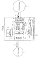
- Fig. 1 is a diagram showing a network configuration in which an IP network 1 and an ATM network 2 are connected to each other via a multiplex transmission apparatus 10.
- the multiplex transmission apparatus 10 loads an ATM cell 4 with an IP packet 3 transmitted from the IP network 1, and transmits the ATM cell 4 to the ATM network 2.
- the multiplex transmission apparatus 10 includes an IP packet receiver 11, a CPS packet generator 12, a QoS distributor 13, a buffer 14, a priority discard controller 15, a QoS controller 16, an ATM cell generator 17, and an ATM cell transmitter 18.
- the IP packet receiver 11 is connected to the CPS packet generator 12.
- the IP packet receiver 11 receives the IP packet 3 transmitted from the IP network 1, and transfers the received IP packet 3 to the CPS packet generator 12.
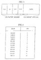
- Fig. 2 shows a configuration of the IP packet 3 received by the IP packet receiver 11.
- IPv4 IP Version 4
- IPv6 IP Version 6
- a "version” field has 4 bits, and indicates a version number (IPv4 or IPv6) of an IP protocol.
- a "data length” field has 4 bits, and indicates a size of an IP packet header.
- a "service type” field has 6 bits, and indicates information concerning the service quality (QoS) requested by an IP packet.
- a "whole data length” field has 16 bits, and indicates the whole length of the IP packet header and an IP packet payload collectively.
- An “identifier (ID)” field has 16 bits, and indicates identification information used for an upper layer to distinguish each IP packet.
- a "flag" field has 3 bits, and indicates information concerning fragment (division) of an IP packet.
- the fragment means dividing a long IP packet and transferring the divided parts.
- a "fragment offset” field has 13 bits, and indicates a location of each fragment in original data.
- a “lifetime (TTL)” field has 8 bits, and indicates time during which existence of an IP packet in the IP network 1 is allowed.
- a "protocol type” field has 8 bits, and indicates a protocol kind of an upper layer.
- a "header check sum" field has 16 bits, and indicates information for conducting a detection check of a transfer error in a header of an IP packet.
- a “source IP address” field has 32 bits, and indicates an IP address of a source terminal.
- a “destination IP address” field has 32 bits, and indicates an IP address of a destination terminal.
- the CPS packet generator 12 is connected to the IP packet receiver 11 and the QoS distributor 13.
- the CPS packet generator 12 generates a CPS packet depending on an IP packet 3 transferred from the IP packet receiver 11, and transmits the generated CPS packet to the QoS distributor 13.
- Fig. 3 shows a configuration of a CPS packet generated by the CPS packet generator 12.
- the CPS packet is an intermediately generated packet of a unit multiplexed onto the VC connection in the AAL2 system.
- a "CID (Channel Identifier)" field has 8 bits, and indicates identification information for identifying an AAL2 connection.
- An “LI” field has 6 bits, and indicates a CPS packet payload length.
- a "UUI (User-to-User Interface)” field has 5 bits, and indicates information concerning division of a SDU (service data unit) processed in the upper layer.
- An “HEC” field is an error correction field having 5 bits.
- the CPS packet generator 12 determines a "CID” corresponding to the "DSCP” and generates a CPS packet in which the determined "CID” is set in the "CID” field.
- the CPS packet generator 12 refers to a table that associates the "DSCP" with the "CID" when determining the "CID". An example of the table is shown in Fig. 4.
- the CPS packet generator 12 is intermediately generated packet generator implemented, depending on first header information of the IP packet 3, to generate an intermediately generated packet (CPS packet) having second header information.
- first header information is the "DSCP”
- second header information is the "CID.”
- the "DSCP” is set in 6 high-order bits of the "service type” field.
- the "DSCP” is set in 6 high-order bits of a "Traffic_Class” field.
- the QoS distributor 13 is connected to the CPS packet generator 12 and the buffer 14.
- the QoS distributor 13 determines a "QoS class" depending on the "CID" set in the CPS packet generated by the CPS packet generator 12, and distributes the CPS packet among buffers 14 1 to 14 n respectively prepared for "QoS classes", depending on the determined "QoS class.”
- the QoS distributor 13 refers to a table that associates the "CID" with the "QoS class" when determining the "QoS class.” An example of the table is shown in Fig. 5.
- the QoS distributor 13 is buffer storage implemented, depending on the second header information (CID), to store the intermediately generated packet (CPS packet) in one of a plurality of buffers 14 1 to 14 n .
- the buffer 14 is connected to the QoS distributor 13, the priority discard controller 15, the QoS controller 16 and the ATM cell generator 17.
- the buffer 14 is a transmission waiting buffer including buffers 14 1 to 14 n for storing CPS packets of respective "QoS classes.”
- the buffer 14 1 stores a CPS packet having a "QoS class" of "1" distributed by the QoS controller 13.
- the priority discard controller 15 is connected to the buffer 14.
- the priority discard controller 15 monitors the number of CPS packets or the amount of data stored in the buffers 14 1 to 14 n .
- the priority discard controller 15 effects a control so as to preferentially discard CPS packets stored in the pertinent buffer included in the buffers 14 1 to 14 n .
- the priority discard controller 15 can set the "discard priorities" of respective CPS packets depending on the "CID” and set a different threshold for each "discard priority.” At this time, the priority discard controller 15 refers to a table that associates the "CID” with the "discard priority” and "threshold.” An example of the table is shown in Fig. 6.
- the priority discard controller 15 conducts a discard control so as to discard CPS packets in which the "CID" is in the range of "1 to 4" (i.e., CPS packets in which the "discard priority” is "1.")
- the priority discard controller 15 conducts a discard control so as to discard CPS packets in which the "CID" is in the range of "1 to 4" (i.e., CPS packets in which the "discard priority” is “1") and CPS packets in which the "CID” is in the range of "5 to 8" (i.e., CPS packets in which the "discard priority” is "2").
- the priority discard controller 15 conducts a discard control so as to discard CPS packets in which the "CID” is in the range of "1 to 4" (i.e., CPS packets in which the "discard priority” is “1"), CPS packets in which the "CID” is in the range of "5 to 8" (i.e., CPS packets in which the "discard priority” is “2”), and CPS packets in which the "CID” is in the range of "9 to 12" (i.e., CPS packets in which the "discard priority” is "3").
- the priority discard controller 15 is discarder implemented, as an amount of intermediately generated packets (CPS packets) stored in the buffers 14 1 to 14 n exceeds a predetermined amount (a threshold concerning the number of packets or the packet data amount), to conduct a discard control on intermediately generated packets (CPS packets) depending on the second header information (CID).
- a predetermined amount a threshold concerning the number of packets or the packet data amount
- the QoS controller 16 is connected to the buffer 14.
- the QoS controller 16 in an order according to QoS conditions that are set by using the "QoS classes" respectively associated with the buffers 14 1 to 14 n , extracts CPS packets from the buffers 14 1 to 14 n into the ATM cell generator 17.
- the order in which the QoS controller 16 extracts CPS packets may correspond to the order of priority set for each "QoS class" or may be subject to scheduling control conducted so as to secure a communication bandwidth set for each "QoS class.”
- the QoS controller 16 is extractor implemented, depending on the QoS class, to extract intermediately generated packets (CPS packets) from the buffers 14 1 to 14 n .
- the ATM cell generator 17 is connected to the buffer 14 and the ATM cell transmitter 18.
- the ATM cell generator 17 generates an ATM cell 4 by loading an ATM cell payload with a CPS packet extracted from the buffer 14, and transmits the generated ATM cell 4 to the ATM cell transmitter 18.
- the ATM cell transmitter 18 is connected to the ATM cell generator 17.
- the ATM cell transmitter 18 transfers the ATM cell 4 transmitted from the ATM cell generator 17 to the ATM network 2 on the VC connection.
- theATM cell generator 17 and theATM cell transmitter 18 form an ATM cell transmitter implemented to load the ATM cell 4 with the intermediately generated packet (CPS) extracted, and transmit the ATM cell 4 to the ATM network 2.
- CPS intermediately generated packet
- the QoS controller 16 successively extracts only CPS packets that generate ATM cells 4 which can be transmitted to the ATM network 2. As a result, it is possible to minimize the delay in the ATM cell transmitter 18 and prevent the communication quality from being degraded.
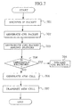
- Fig. 7 is a flow chart showing an operation conducted when the multiplex transmission apparatus 10 transfers an IP packet transmitted from the IP network 1, to the ATM network 2.
- the IP packet receiver 11 receives an IP packet 3 transmitted from the IP network 1 at step 701.
- the CPS packet generator 12 refers to the table shown in Fig. 4 depending on a "DSCP” set in the "service type” field of the IP packet 3, and generates a CPS packet having a "CID” corresponding to the "DSCP” set in its "CID” field.
- the QoS distributor 13 refers to the table shown in Fig. 5 depending on the "CID" set in the CPS packet generated by the CPS packet generator 12, and determines a "QoS class" corresponding to the "CID.”
- the QoS distributor 13 distributes the CPS packet among the buffers 141 to 14n respectively prepared for "QoS classes.”
- the priority discard controller 15 refers to the table shown in Fig. 6 when the CPS packet is distributed among the buffers 14 1 to 14 n , and effects monitoring to determine whether the number of CPS packets or data amount exceeds a threshold of each "discard priority" for each of the buffers 14 1 to 14 n .
- the priority discard controller 15 preferentially discards CPS packets of the "discard priority" stored in the pertinent buffer included in the buffers 14 1 to 14n.
- the QoS controller 16 in an order according to QoS conditions that are set by using the "QoS classes" respectively associated with the buffers 14 1 to 14 n , extracts CPS packets from the buffers 14 1 to 14 n into the ATM cell generator 17.
- the ATM cell generator 17 generates an ATM cell 4 by loading an ATM cell payload with the CPS packet extracted from the buffer 14, and transmits the generated ATM cell 4 to the ATM cell transmitter 18.
- the ATM cell transmitter 18 transfers the ATM cell 4 transmitted from the ATM cell generator 17 to the ATM network 2 on the VC connection.
- the CPS packet generator 12 generates, depending on the "DSCP" (first header information) of the IP packet 3, a CPS packet (intermediately generated packet) having a different "CID" (second header information).
- the ATM cell generator 17 loads an ATM cell 4 with the generated CPS packet (intermediately generated packet). In the ATM network 2, therefore, it is possible to conduct a traffic control according to the QoS condition set in the IP packet 3.
- the priority discard controller 15 conducts a discard control according to the "CID" (second header information) generated based on the "DSCP" (first header information) of the IP packet 3.
- CID second header information
- DSCP first header information
- Fig. 8 is a diagram showing a network configuration in which an IP network 1 and an ATM network 2 are connected to each other via a multiplex transmission apparatus 20.
- the multiplex transmission apparatus 20 loads an ATM cell 4 with an IP packet 3 transmitted from the IP network 1, and transmits the ATM cell 4 to the ATM network 2.
- the multiplex transmission apparatus 20 includes an IP packet receiver 21, a CPS packet generator 22, a QoS distributor 23, a buffer 24, a priority discard controller 25, a QoS controller 26, an ATM cell generator 27, and an ATM cell transmitter 28.
- the IP packet receiver 21 is connected to the CPS packet generator 22.
- the IP packet receiver 21 receives the IP packet 3 transmitted from the IP network 1, and transfers the received IP packet 3 to the CPS packet generator 22.
- the CPS packet generator 22 is connected to the IP packet receiver 21 and the ATM cell generator 27.
- the CPS packet generator 22 refers to the table shown in Fig. 4, and generates a CPS packet based on an IP packet 3 transferred from the IP packet receiver 21, and then transmits the generated CPS packet to the ATM cell generator 27.
- the CPS packet generator 22 is an intermediately generated packet generator implemented, depending on first header information (DSCP) of the IP packet 3, to generate an intermediately generated packet (CPS packet) having second header information (CID).
- DSCP first header information
- CID second header information
- the ATM cell generator 27 is connected to the CPS packet generator 22 and the QoS distributor 23.
- the ATM cell generator 27 determines a "VCI (third header information)" based on the "CID" set in the CPS packet transmitted from the CPS packet generator 22, generates an ATM cell 4 by using the determined "VCI,” and transmits the generated ATM cell 4 to the QoS distributor 23.
- VCI third header information
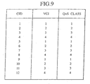
- the ATM cell generator 27 refers to a table that associates the "CID" with the "VCI” when determining the "VCI.” An example of the table is shown in Fig. 9.
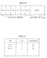
- Fig. 10 shows an example of a configuration of an ATM cell 4 generated by the ATM cell generator 27.
- a "GFC (Generic Flow Control)" field has 4 bits, and indicates flow control information for preventing cell collision in a user-network interface (UNI).
- a "VPI” field has 8 bits, and indicates identification information for identifying a VP (Virtual Path).
- a "VCI” field has 16 bits, and indicates identification information for identifying a VC (Virtual Channel).
- a "PT (Payload Type)" field has 3 bits, and indicates an information kind included in an ATM cell payload.
- a "CLP” field has 1 bit, and indicates an ATM cell to be discarded preferentially at the time of congestion in the ATM network.
- An “HEC” field is an error correction field having 8 bits.
- the ATM cell generator 27 determines a "CLP (fourth header information)" corresponding to the "CID" of the CPS packet transmitted from the CPS packet generator 22.
- the ATM cell generator 27 When determining the "CLP,” the ATM cell generator 27 refers to a table that associates the "CID" with the "CLP.” An example of the table is shown in Fig. 11.
- the ATM cell generator 27 sets the determined "CLP" and generates an ATM cell 4.
- the ATM cell generator 27 is ATM cell generator implemented to load the ATM cell 4 with the intermediately generated packet (CPS packet).
- the ATM cell generator 27 generates an ATM cell 4 by loading an ATM cell payload with one CPS packet. Furthermore, the ATM cell generator 27 can also generate an ATM cell 4 by loading an ATM cell payload collectively with CPS packets having the same "CID.”
- the QoS distributor 23 is connected to the ATM cell generator 27 and the buffer 24.
- the QoS distributor 23 determines a "QoS class" based on the "VCI” set in the ATM cell generated by the ATM cell generator 27, and distributes the ATM cell among buffers 24 1 to 24 n respectively prepared for "QoS classes", based on the determined "QoS class.”
- the QoS distributor 23 When determining the "QoS class,” the QoS distributor 23 refers to a table that associates the "VCI" with the "QoS class.” An example of the table is shown in Fig. 9.
- the QoS distributor 23 is buffer storage implemented, depending on the third header information (VCI), to store the ATM cell 4 in one of a plurality of buffers 24 1 to 24 n
- the buffer 24 is connected to the QoS distributor 23, the priority discard controller 25, the QoS controller 26 and the ATM cell transmitter 28.
- the buffer 24 is a transmission waiting buffer including buffers 24 1 to 24 n for storing ATM cells 4 of respective "QoS classes.”
- the buffer 24 1 stores an ATM cell 4 having a "QoS class" of "1" distributed by the QoS controller 23.
- the priority discard controller 25 is connected to the buffer 24.
- the priority discard controller 25 monitors the number of ATM cells 4 stored in the buffers 24 1 to 24 n . When the number of ATM cells 4 has exceeded a threshold, the priority discard controller 25 effects a control so as to preferentially discard ATM cells 4 stored in the pertinent buffer included in the buffers 24 1 to 24 n .
- the priority discard controller 25 can set a different threshold for each "CLP" of the ATM cell 4.
- the priority discard controller 25 conducts a discard control so as to preferentially discard ATM cells 4 in which the "CLP" is "0.”
- the priority discard controller 25 conducts a discard control so as to preferentially discard ATM cells 4 in which the "CLP" is "0" and ATM cells 4 in which the "CLP” is "1.”
- the priority discard controller 25 is discarder implemented, as an amount of ATM cells 4 stored in the buffers 24 1 to 24 n exceeds a predetermined amount (a threshold concerning the number of packets), to conduct a discard control on ATM cells 4 depending on the fourth header information (CLP) of the ATM cells 4.
- a predetermined amount a threshold concerning the number of packets
- the QoS controller 26 is connected to the buffer 24.
- the order in which the QoS controller 26 extracts the ATM cells 4 may correspond to the order of priority set every "QoS class" or may be subject to scheduling control conducted so as to secure a communication bandwidth set for each "QoS class.”
- the QoS controller 26 is extractor implemented, depending on the QoS class, to extract ATM cells 4 from the buffers 24 1 to 24 n .
- the ATM cell transmitter 28 is connected to the buffer 24.
- the ATM cell transmitter 28 transfers an ATM cell 4 extracted from the buffer 24, to the ATM network 2 on the VC connection.
- the ATM cell transmitter 28 is ATM cell transmitter implemented to transmit the ATM cell 4 extracted, to the ATM network 2.
- Fig. 12 is a flow chart showing an operation conducted when the multiplex transmission apparatus 20 transfers an IP packet transmitted from the IP network 1, to the ATM network 2.
- the IP packet receiver 21 receives an IP packet 3 transmitted from the IP network 1 at step 1001.
- the CPS packet generator 22 refers to the table shown in Fig. 4 based on a "DSCP" set in the "service type” field of the IP packet 3, and generates a CPS packet having a "CID” corresponding to the "DSCP” set in its "CID” field.
- the ATM cell generator 27 refers to the table shown in Fig. 9, determines a "VCI” based on the "CID" set in the CPS packet transmitted from the CPS packet generator 22, and generates an ATM cell 4 by using the determined "VCI.”
- the ATM cell generator 27 determines a "discard priority" corresponding to the "CID" of the CPS packet transmitted from the CPS packet generator 22. And the ATM cell generator 27 determines a "CLP” according to the determined “discard priority,” sets the determined “CLP,” and generates an ATM cell 4.
- the QoS distributor 23 refers to the table shown in Fig. 9 based on the "VCI" set in the ATM cell generated by the ATM cell generator 27, and determines a "QoS class" corresponding to the "VCI.” Depending on the determined "QoS class,” the QoS distributor 23 distributes the ATM cell 4 among the buffers 24 1 to 24 n prepared for respective "QoS classes.”
- the priority discard controller 25 effects monitoring to determine, when the ATM cell 4 is distributed among the buffers 24 1 to 24 n , whether the number of ATM cells 4 exceeds a threshold corresponding to each "CLP", for each of the buffers 24 1 to 24 n .
- the priority discard controller 25 preferentially discards ATM cells 4 having a "CLP" equivalent to "0" stored in the pertinent buffer included in the buffers 24 1 to 24 n .
- the QoS controller 26 in an order according to QoS conditions that are set by using the "QoS classes" respectively associated with the buffers 24 1 to 24 n , extracts ATM cells from the buffers 24 1 to 24 n into the ATM cell transmitter 28.
- the ATM cell transmitter 28 transfers the ATM cell 4 extracted from the buffer 24, to the ATM network 2 on the VC connection.
- the CPS packet generator 22 generates, depending on the "DSCP" (first header information) of the IP packet 3, a CPS packet (intermediately generated packet) having a different "CID" (second header information).
- the ATM cell generator 27 loads an ATM cell 4 with the generated CPS packet (intermediately generated packet). In the ATM network 2, therefore, it is possible to conduct a traffic control according to the QoS condition set in the IP packet 3.
- the priority discard controller 25 conducts a discard control according to the "CLP" (fourth header information) generated based on the "DSCP" (first header information) of the IP packet 3. In the ATM network 2, therefore, it is possible to conduct a discard priority control according to the QoS condition set in the IP packet 3.
- the ATM cell generator 27 loads an ATM cell 4 with one CPS packet (intermediately generated packet). Therefore, it is possible to prevent a delay caused by generating the ATM cell 4.
- the ATM cell generator 27 loads one ATM cell 4 with CPS packets (intermediately generated packets) having the same "CID" (second header information). Therefore, it is possible to discard CPS packets having the same discard priority when discarding an ATM cell 4.
- the QoS class management and the discard priority control are conducted at the ATM cell level. Therefore, it is not necessary to conduct the QoS class management and the discard priority control using the AAL2 system.
- the present invention it becomes possible to provide a multiplex transmission apparatus and a multiplex transmission method that make it possible to conduct a traffic control and discard priority control corresponding to the Diffserv system when transferring IP packets 3 having a plurality of QoS conditions set therein, in the ATM network 2.
Landscapes
- Engineering & Computer Science (AREA)
- Computer Networks & Wireless Communication (AREA)
- Signal Processing (AREA)
- Data Exchanges In Wide-Area Networks (AREA)
- Time-Division Multiplex Systems (AREA)
Abstract
Description
Claims (20)
- A multiplex transmission apparatus (20) implemented to load an ATM cell (4) with an IP packet (3) and transmit the ATM cell (4) to an ATM network (2), characterized by comprising:an intermediately generated packet generator (22) implemented, depending on DiffServ Code Point (DSCP) header information of the IP packet (3), to generate an intermediately generated packet having Channel Identifier (CID) header information;an ATM cell generator (27) implemented to load the ATM cell (4) with the intermediately generated packet;a buffer storage (24) implemented, depending on Virtual Channel Identifier (VCI) header information of the ATM cell (4), to store the ATM cell (4) in one of a plurality of transmission waiting buffers (241, 242, 24n);an extractor (26) implemented, depending on the VCI header information of the ATM cell (4), to extract the ATM cell (4) from the transmission waiting buffer (241, 242, 24n); andan ATM cell transmitter (28) implemented to transmit the ATM cell (4) extracted, to the ATM network (2).
- The multiplex transmission apparatus (20) according to claim 1, comprising a discarder (25) implemented, as an amount of the ATM cells (4) stored in the transmission waiting buffer (241, 242, 24n) exceeds a predetermined amount, to conduct a discard control on the ATM cells (4) depending on Cell Loss Priority (CLP) header information of the ATM cell (4).
- The multiplex transmission apparatus (20) according to claim 1 or 2, wherein the ATM cell generator (22) loads the ATM cell (4) with one intermediately generated packet.
- The multiplex transmission apparatus (20) according to claim 1 or 2, wherein the ATM cell generator (22) loads the ATM cell (4) with the intermediately generated packets having the same CID header information.
- A multiplex transmission method of loading an ATM cell (4) with an IP packet (3) and transmitting the ATM cell (4) to an ATM network (2), characterized by comprising:A) generating, depending on DiffServ Code Point (DSCP) header information of the IP packet (3), an intermediately generated packet having Channel Identifier (CID) header information;B) loading the ATM cell (4) with the intermediately generated packet;C) storing, depending on Virtual Channel Identifier (VCI) header information of the ATM cell (4), the ATM cell (4) in one of a plurality of transmission waiting buffers (241, 242, 24n);D) extracting, depending on the VCI header information of the ATM cell (4), the ATM cell (4) from the transmission waiting buffer (241, 242, 24n); andE) transmitting the ATM cell (4) extracted, to the ATM network (2).
- The multiplex transmission method according to Claim 5 comprising:F) conducting a discard control on the ATM cells (4) depending on Cell Loss Priority (CLP) header information of the ATM cell (4), as an amount of the ATM cells (4) stored in the transmission waiting buffer (141, 142, 14n) exceeds a predetermined amount.
- The Multiplex transmission method according to claim 5 or 6, wherein, in the step B) the ATM cell (4) is loaded with one intermediately generated packet.
- The multiplex transmission method according to claim 5 or 6, wherein, in the step B), the ATM cell (4) is loaded with the intermediately generated packets having the same VCI header information.
- A multiplex transmission apparatus implemented to load an ATM cell with an IP packet and transmit the ATM cell to an ATM network, the multiplex transmission apparatus comprising:an intermediately generated packet generator implemented, depending on first header information of the IP packet, to generate an intermediately generated packet having second header information;a buffer storage implemented, depending on the second header information, to store the intermediately generated packet in one of a plurality of transmission waiting buffers;a extractor implemented, depending on the second header information, to extract the intermediately generated packet from the transmission waiting buffer; andan ATM cell transmitter implemented to load the ATM cell with the intermediately generated packet extracted and transmit the ATM cell to the ATM network.
- The multiplex transmission apparatus according to claim 9 ,comprising a discarder implemented, as an amount of the intermediately generated packets stored in the transmission waiting buffer exceeds a predetermined amount, to conduct a discard control on the intermediately generated packets depending on the second header information.
- A multiplex transmission apparatus implemented to load an ATM cell with an IP packet and transmit the ATM cell to an ATM network, the multiplex transmission apparatus comprising:an intermediately generated packet generator implemented, depending on first header information of the IP packet, to generate an intermediately generated packet having second header information;an ATM cell generator implemented to load the ATM cell with the intermediately generated packet;a buffer storage implemented, depending on third header information of the ATM cell, to store the ATM cell in one of a plurality of transmission waiting buffers;a extractor implemented, depending on the third header information of the ATM cell, to extract the ATM cell from the transmission waiting buffer; andan ATM cell transmitter implemented to transmit the ATM cell extracted, to the ATM network.
- The multiplex transmission apparatus according to claim 11, comprising a discarder implemented, as an amount of the ATM cells stored in the transmission waiting buffer exceeds a predetermined amount, to conduct a discard control on the ATM cells depending on fourth header information of the ATM cell.
- The multiplex transmission apparatus according to claim 11 wherein the ATM cell generator loads the ATM cell with one intermediately generated packet.
- The multiplex transmission apparatus according to claim 11, wherein the ATM cell generator loads the ATM cell with the intermediately generated packets having the same second header information.
- A multiplex transmission method of loading an ATM cell with an IP packet and transmitting the ATM cell to an ATM network, comprising the steps of:A) generating, depending on first header information of the IP packet, an intermediately generated packet having second header information;B) storing, depending on the second header information, the intermediately generated packet in one of a plurality of transmission waiting buffers;C) extracting, depending on the second header information, the intermediately generated packet from the transmission waiting buffer; andD) loading the ATM cell with the intermediately generated packet extracted and transmitting the ATM cell to the ATM network.
- The multiplex transmission method according to claim 15, comprising the step of:E) conducting a discard control on the intermediately generated packets depending on the second header information, as an amount of the intermediately generated packets stored in the transmission waiting buffer exceeds a predetermined amount.
- A multiplex transmission method of loading an ATM cell with an IP packet and transmitting the ATM cell to an ATM network, comprising the steps of:A) generating, depending on first header information of the IP packet, an intermediately generated packet having second header information;B) loading the ATM cell with the intermediately generated packet;C) storing, depending on third header information of the ATM cell, the ATM cell in one of a plurality of transmission waiting buffers;D) extracting, depending on the third header information of the ATM cell, the ATM cell from the transmission waiting buffer; andE) transmitting the ATM cell extracted, to the ATM network.
- The multiplex transmission method according to claim 17, comprising the step of;F) conducting a discard control on the ATM cells depending on fourth header information of the ATM cell, as an amount of the ATM cells stored in the transmission waiting buffer exceeds a predetermined amount.
- The multiplex transmission method according to claim 17, wherein, in the step B), the ATM cell is loaded with one intermediately generated packet.
- The multiplex transmission method according to claim 17, wherein, in the step B), the ATM cell is loaded with the intermediately generated packets having the same second header information.
Applications Claiming Priority (3)
| Application Number | Priority Date | Filing Date | Title |
|---|---|---|---|
| JP2001258582A JP3808736B2 (en) | 2001-08-28 | 2001-08-28 | Multiplex transmission apparatus and multiple transmission method |
| JP2001258582 | 2001-08-28 | ||
| EP20020018299 EP1289334B1 (en) | 2001-08-28 | 2002-08-26 | Multiplex transmission apparatus and multiplex transmission method |
Related Parent Applications (2)
| Application Number | Title | Priority Date | Filing Date |
|---|---|---|---|
| EP20020018299 Division EP1289334B1 (en) | 2001-08-28 | 2002-08-26 | Multiplex transmission apparatus and multiplex transmission method |
| EP02018299.4 Division | 2002-08-26 |
Publications (3)
| Publication Number | Publication Date |
|---|---|
| EP1473895A2 true EP1473895A2 (en) | 2004-11-03 |
| EP1473895A3 EP1473895A3 (en) | 2005-06-15 |
| EP1473895B1 EP1473895B1 (en) | 2011-10-05 |
Family
ID=19086075
Family Applications (2)
| Application Number | Title | Priority Date | Filing Date |
|---|---|---|---|
| EP20020018299 Expired - Lifetime EP1289334B1 (en) | 2001-08-28 | 2002-08-26 | Multiplex transmission apparatus and multiplex transmission method |
| EP20040017725 Expired - Lifetime EP1473895B1 (en) | 2001-08-28 | 2002-08-26 | Multiplex transmission apparatus and multiplex transmission method |
Family Applications Before (1)
| Application Number | Title | Priority Date | Filing Date |
|---|---|---|---|
| EP20020018299 Expired - Lifetime EP1289334B1 (en) | 2001-08-28 | 2002-08-26 | Multiplex transmission apparatus and multiplex transmission method |
Country Status (9)
| Country | Link |
|---|---|
| US (1) | US7382783B2 (en) |
| EP (2) | EP1289334B1 (en) |
| JP (1) | JP3808736B2 (en) |
| CN (1) | CN100433671C (en) |
| AT (2) | ATE527826T1 (en) |
| AU (1) | AU2002300741B2 (en) |
| CA (1) | CA2399935C (en) |
| DE (1) | DE60221472T2 (en) |
| ES (2) | ES2372278T3 (en) |
Families Citing this family (12)
| Publication number | Priority date | Publication date | Assignee | Title |
|---|---|---|---|---|
| US7286483B2 (en) * | 2002-11-14 | 2007-10-23 | Intel Corporation | Electronic data transfer based on selective storage of incoming packets |
| US7324517B1 (en) * | 2003-04-16 | 2008-01-29 | Cisco Technology, Inc. | Converting data packets in a communication network |
| WO2004112318A1 (en) * | 2003-06-11 | 2004-12-23 | Ntt Docomo, Inc. | Packet communication method, controller and mobile station |
| WO2004112406A1 (en) * | 2003-06-18 | 2004-12-23 | Utstarcom (China) Co. Ltd. | Method for implementing diffserv in the wireless access network of the universal mobile telecommunication system |
| CN1788463A (en) * | 2003-07-07 | 2006-06-14 | Ut斯达康(中国)有限公司 | Method for realizing differentiated service code point marking in UMTS Radio Access Network (RAN) based on IP |
| WO2005009060A1 (en) * | 2003-07-16 | 2005-01-27 | Utstarcom (China) Co., Ltd. | A distributing radio network controller based on ip switch |
| WO2005009065A1 (en) * | 2003-07-17 | 2005-01-27 | Utstarcom (China) Co., Ltd. | A method for improving service quality in universal mobile telecomunications system (umts) radio |
| CN100377545C (en) * | 2004-03-13 | 2008-03-26 | 鸿富锦精密工业(深圳)有限公司 | Network quality service system and method |
| US7102194B2 (en) * | 2004-08-16 | 2006-09-05 | System General Corp. | High voltage and low on-resistance LDMOS transistor having radiation structure and isolation effect |
| US7606158B2 (en) * | 2004-09-24 | 2009-10-20 | Cisco Technology, Inc. | Hierarchical flow control for router ATM interfaces |
| KR100955154B1 (en) | 2007-11-29 | 2010-04-28 | 엘지노텔 주식회사 | CD allocation management method of AAL2 node |
| CN102137008B (en) * | 2011-01-24 | 2013-08-07 | 华为技术有限公司 | Method, device and system for maintaining quality of service (QoS) |
Family Cites Families (15)
| Publication number | Priority date | Publication date | Assignee | Title |
|---|---|---|---|---|
| US5408472A (en) * | 1993-09-20 | 1995-04-18 | Motorola, Inc. | Device and method for cell processing in cell relay nodes |
| US6021263A (en) * | 1996-02-16 | 2000-02-01 | Lucent Technologies, Inc. | Management of ATM virtual circuits with resources reservation protocol |
| JPH1141293A (en) * | 1997-07-15 | 1999-02-12 | Nec Corp | Exchange equipment |
| US6041054A (en) * | 1997-09-24 | 2000-03-21 | Telefonaktiebolaget Lm Ericsson | Efficient transport of internet protocol packets using asynchronous transfer mode adaptation layer two |
| WO1999034558A1 (en) * | 1997-12-25 | 1999-07-08 | Kabushiki Kaisha Toshiba | Atm repeater and network including the same |
| US6219339B1 (en) * | 1998-02-20 | 2001-04-17 | Lucent Technologies Inc. | Method and apparatus for selectively discarding packets |
| WO2000030401A1 (en) * | 1998-11-13 | 2000-05-25 | Nortel Networks Corporation | Method and apparatus for support of ip differentiated service over mpoa |
| US6385170B1 (en) * | 1998-12-29 | 2002-05-07 | At&T Corp. | Method and system for dynamically triggering flow-based quality of service shortcuts through a router |
| US6430154B1 (en) * | 1999-08-13 | 2002-08-06 | Fujitsu Network Communications, Inc. | Supporting multiple application traffic types over connection oriented networks |
| US6757249B1 (en) * | 1999-10-14 | 2004-06-29 | Nokia Inc. | Method and apparatus for output rate regulation and control associated with a packet pipeline |
| JP3478218B2 (en) * | 1999-12-27 | 2003-12-15 | 日本電気株式会社 | Edge node exchanges and exchanges |
| US6654376B1 (en) * | 1999-12-28 | 2003-11-25 | Nortel Networks Limited | ATM packet scheduler |
| JP3386117B2 (en) * | 2000-01-11 | 2003-03-17 | 日本電気株式会社 | Multilayer class identification communication device and communication device |
| US6940862B2 (en) * | 2001-06-25 | 2005-09-06 | Mark Goudreau | Apparatus and method for classifying packets |
| JP2003143189A (en) * | 2001-10-31 | 2003-05-16 | Fujitsu Ltd | Communications system |
-
2001
- 2001-08-28 JP JP2001258582A patent/JP3808736B2/en not_active Expired - Fee Related
-
2002
- 2002-08-26 AT AT04017725T patent/ATE527826T1/en not_active IP Right Cessation
- 2002-08-26 EP EP20020018299 patent/EP1289334B1/en not_active Expired - Lifetime
- 2002-08-26 ES ES04017725T patent/ES2372278T3/en not_active Expired - Lifetime
- 2002-08-26 EP EP20040017725 patent/EP1473895B1/en not_active Expired - Lifetime
- 2002-08-26 AT AT02018299T patent/ATE369025T1/en not_active IP Right Cessation
- 2002-08-26 CN CNB021420858A patent/CN100433671C/en not_active Expired - Fee Related
- 2002-08-26 ES ES02018299T patent/ES2289034T3/en not_active Expired - Lifetime
- 2002-08-26 DE DE2002621472 patent/DE60221472T2/en not_active Expired - Lifetime
- 2002-08-27 AU AU2002300741A patent/AU2002300741B2/en not_active Ceased
- 2002-08-27 US US10/228,137 patent/US7382783B2/en not_active Expired - Fee Related
- 2002-08-28 CA CA 2399935 patent/CA2399935C/en not_active Expired - Fee Related
Also Published As
| Publication number | Publication date |
|---|---|
| DE60221472T2 (en) | 2008-04-30 |
| ATE369025T1 (en) | 2007-08-15 |
| EP1473895A3 (en) | 2005-06-15 |
| ES2372278T3 (en) | 2012-01-18 |
| JP2003069633A (en) | 2003-03-07 |
| US20030043809A1 (en) | 2003-03-06 |
| DE60221472D1 (en) | 2007-09-13 |
| CA2399935A1 (en) | 2003-02-28 |
| CA2399935C (en) | 2008-07-22 |
| CN1402483A (en) | 2003-03-12 |
| US7382783B2 (en) | 2008-06-03 |
| CN100433671C (en) | 2008-11-12 |
| EP1289334A2 (en) | 2003-03-05 |
| JP3808736B2 (en) | 2006-08-16 |
| AU2002300741B2 (en) | 2005-12-15 |
| ES2289034T3 (en) | 2008-02-01 |
| EP1289334B1 (en) | 2007-08-01 |
| EP1289334A3 (en) | 2003-10-01 |
| EP1473895B1 (en) | 2011-10-05 |
| ATE527826T1 (en) | 2011-10-15 |
Similar Documents
| Publication | Publication Date | Title |
|---|---|---|
| US6611522B1 (en) | Quality of service facility in a device for performing IP forwarding and ATM switching | |
| EP0761053B1 (en) | Method and equipment for prioritizing traffic in an atm network | |
| US6618378B1 (en) | Method and apparatus for supporting multiple class of service connections in a communications network | |
| JP3607017B2 (en) | Feedback control device and cell scheduling device in cell switch | |
| US6411617B1 (en) | System and method for managing data traffic associated with various quality of service principles using a conventional network node switch | |
| AU783314B2 (en) | Router device and priority control method for use in the same | |
| US7382783B2 (en) | Multiplex transmission apparatus and multiplex transmission method for encapsulating data within a connectionless payload | |
| US20030120796A1 (en) | Method for controlling congestion in connection section between ATM network and NON-ATM network | |
| US6567378B1 (en) | Cell discard scheme for IP traffic over a cell relay infrastructure | |
| US8780898B2 (en) | Processor for packet switching between cell streams with optional virtual channel and channel identification modification | |
| US6665302B2 (en) | Method and system for handling a loop back connection using a priority unspecified bit rate in ADSL interface | |
| US6788706B1 (en) | Frame handling system, and frame handling method | |
| KR100369369B1 (en) | A Virtual Channel Merge Apparatus MutiProtocol Label Switch System | |
| JP3382517B2 (en) | Priority control circuit | |
| Ng et al. | Incorporating priority scheme in IPv6 over ATM networks | |
| JP2001007808A (en) | Traffic shaping device | |
| KR19990048607A (en) | Device and control method of cell buffer in ATM switch | |
| KR19990058026A (en) | Traffic Control Method Using Cell Priority of Hybrid Protocol Converter |
Legal Events
| Date | Code | Title | Description |
|---|---|---|---|
| PUAI | Public reference made under article 153(3) epc to a published international application that has entered the european phase |
Free format text: ORIGINAL CODE: 0009012 |
|
| AC | Divisional application: reference to earlier application |
Ref document number: 1289334 Country of ref document: EP Kind code of ref document: P |
|
| AK | Designated contracting states |
Kind code of ref document: A2 Designated state(s): AT BE BG CH CY CZ DE DK EE ES FI FR GB GR IE IT LI LU MC NL PT SE SK TR |
|
| AX | Request for extension of the european patent |
Extension state: AL LT LV MK |
|
| PUAL | Search report despatched |
Free format text: ORIGINAL CODE: 0009013 |
|
| AK | Designated contracting states |
Kind code of ref document: A3 Designated state(s): AT BE BG CH CY CZ DE DK EE ES FI FR GB GR IE IT LI LU MC NL PT SE SK TR |
|
| AX | Request for extension of the european patent |
Extension state: AL LT LV MK |
|
| RIC1 | Information provided on ipc code assigned before grant |
Ipc: 7H 04Q 11/04 A Ipc: 7H 04L 12/56 B |
|
| 17P | Request for examination filed |
Effective date: 20050727 |
|
| AKX | Designation fees paid |
Designated state(s): AT BE BG CH CY CZ DE DK EE ES FI FR GB GR IE IT LI LU MC NL PT SE SK TR |
|
| GRAP | Despatch of communication of intention to grant a patent |
Free format text: ORIGINAL CODE: EPIDOSNIGR1 |
|
| GRAS | Grant fee paid |
Free format text: ORIGINAL CODE: EPIDOSNIGR3 |
|
| RAP1 | Party data changed (applicant data changed or rights of an application transferred) |
Owner name: NTT DOCOMO, INC. |
|
| GRAA | (expected) grant |
Free format text: ORIGINAL CODE: 0009210 |
|
| AC | Divisional application: reference to earlier application |
Ref document number: 1289334 Country of ref document: EP Kind code of ref document: P |
|
| AK | Designated contracting states |
Kind code of ref document: B1 Designated state(s): AT BE BG CH CY CZ DE DK EE ES FI FR GB GR IE IT LI LU MC NL PT SE SK TR |
|
| REG | Reference to a national code |
Ref country code: GB Ref legal event code: FG4D |
|
| REG | Reference to a national code |
Ref country code: CH Ref legal event code: EP |
|
| REG | Reference to a national code |
Ref country code: IE Ref legal event code: FG4D |
|
| REG | Reference to a national code |
Ref country code: DE Ref legal event code: R096 Ref document number: 60241274 Country of ref document: DE Effective date: 20111201 |
|
| REG | Reference to a national code |
Ref country code: SE Ref legal event code: TRGR |
|
| REG | Reference to a national code |
Ref country code: ES Ref legal event code: FG2A Ref document number: 2372278 Country of ref document: ES Kind code of ref document: T3 Effective date: 20120118 |
|
| REG | Reference to a national code |
Ref country code: NL Ref legal event code: VDEP Effective date: 20111005 |
|
| REG | Reference to a national code |
Ref country code: AT Ref legal event code: MK05 Ref document number: 527826 Country of ref document: AT Kind code of ref document: T Effective date: 20111005 |
|
| PG25 | Lapsed in a contracting state [announced via postgrant information from national office to epo] |
Ref country code: BE Free format text: LAPSE BECAUSE OF FAILURE TO SUBMIT A TRANSLATION OF THE DESCRIPTION OR TO PAY THE FEE WITHIN THE PRESCRIBED TIME-LIMIT Effective date: 20111005 |
|
| PG25 | Lapsed in a contracting state [announced via postgrant information from national office to epo] |
Ref country code: NL Free format text: LAPSE BECAUSE OF FAILURE TO SUBMIT A TRANSLATION OF THE DESCRIPTION OR TO PAY THE FEE WITHIN THE PRESCRIBED TIME-LIMIT Effective date: 20111005 Ref country code: PT Free format text: LAPSE BECAUSE OF FAILURE TO SUBMIT A TRANSLATION OF THE DESCRIPTION OR TO PAY THE FEE WITHIN THE PRESCRIBED TIME-LIMIT Effective date: 20120206 Ref country code: GR Free format text: LAPSE BECAUSE OF FAILURE TO SUBMIT A TRANSLATION OF THE DESCRIPTION OR TO PAY THE FEE WITHIN THE PRESCRIBED TIME-LIMIT Effective date: 20120106 |
|
| PG25 | Lapsed in a contracting state [announced via postgrant information from national office to epo] |
Ref country code: CY Free format text: LAPSE BECAUSE OF FAILURE TO SUBMIT A TRANSLATION OF THE DESCRIPTION OR TO PAY THE FEE WITHIN THE PRESCRIBED TIME-LIMIT Effective date: 20111005 |
|
| PG25 | Lapsed in a contracting state [announced via postgrant information from national office to epo] |
Ref country code: EE Free format text: LAPSE BECAUSE OF FAILURE TO SUBMIT A TRANSLATION OF THE DESCRIPTION OR TO PAY THE FEE WITHIN THE PRESCRIBED TIME-LIMIT Effective date: 20111005 Ref country code: SK Free format text: LAPSE BECAUSE OF FAILURE TO SUBMIT A TRANSLATION OF THE DESCRIPTION OR TO PAY THE FEE WITHIN THE PRESCRIBED TIME-LIMIT Effective date: 20111005 Ref country code: CZ Free format text: LAPSE BECAUSE OF FAILURE TO SUBMIT A TRANSLATION OF THE DESCRIPTION OR TO PAY THE FEE WITHIN THE PRESCRIBED TIME-LIMIT Effective date: 20111005 Ref country code: BG Free format text: LAPSE BECAUSE OF FAILURE TO SUBMIT A TRANSLATION OF THE DESCRIPTION OR TO PAY THE FEE WITHIN THE PRESCRIBED TIME-LIMIT Effective date: 20120105 Ref country code: DK Free format text: LAPSE BECAUSE OF FAILURE TO SUBMIT A TRANSLATION OF THE DESCRIPTION OR TO PAY THE FEE WITHIN THE PRESCRIBED TIME-LIMIT Effective date: 20111005 |
|
| PLBE | No opposition filed within time limit |
Free format text: ORIGINAL CODE: 0009261 |
|
| STAA | Information on the status of an ep patent application or granted ep patent |
Free format text: STATUS: NO OPPOSITION FILED WITHIN TIME LIMIT |
|
| PG25 | Lapsed in a contracting state [announced via postgrant information from national office to epo] |
Ref country code: IT Free format text: LAPSE BECAUSE OF FAILURE TO SUBMIT A TRANSLATION OF THE DESCRIPTION OR TO PAY THE FEE WITHIN THE PRESCRIBED TIME-LIMIT Effective date: 20111005 |
|
| 26N | No opposition filed |
Effective date: 20120706 |
|
| PGFP | Annual fee paid to national office [announced via postgrant information from national office to epo] |
Ref country code: GB Payment date: 20120822 Year of fee payment: 11 |
|
| REG | Reference to a national code |
Ref country code: DE Ref legal event code: R097 Ref document number: 60241274 Country of ref document: DE Effective date: 20120706 |
|
| PGFP | Annual fee paid to national office [announced via postgrant information from national office to epo] |
Ref country code: DE Payment date: 20120822 Year of fee payment: 11 |
|
| PG25 | Lapsed in a contracting state [announced via postgrant information from national office to epo] |
Ref country code: AT Free format text: LAPSE BECAUSE OF FAILURE TO SUBMIT A TRANSLATION OF THE DESCRIPTION OR TO PAY THE FEE WITHIN THE PRESCRIBED TIME-LIMIT Effective date: 20111005 |
|
| REG | Reference to a national code |
Ref country code: CH Ref legal event code: PL |
|
| PG25 | Lapsed in a contracting state [announced via postgrant information from national office to epo] |
Ref country code: MC Free format text: LAPSE BECAUSE OF NON-PAYMENT OF DUE FEES Effective date: 20120831 |
|
| PG25 | Lapsed in a contracting state [announced via postgrant information from national office to epo] |
Ref country code: CH Free format text: LAPSE BECAUSE OF NON-PAYMENT OF DUE FEES Effective date: 20120831 Ref country code: LI Free format text: LAPSE BECAUSE OF NON-PAYMENT OF DUE FEES Effective date: 20120831 |
|
| REG | Reference to a national code |
Ref country code: IE Ref legal event code: MM4A |
|
| PG25 | Lapsed in a contracting state [announced via postgrant information from national office to epo] |
Ref country code: IE Free format text: LAPSE BECAUSE OF NON-PAYMENT OF DUE FEES Effective date: 20120826 |
|
| PGFP | Annual fee paid to national office [announced via postgrant information from national office to epo] |
Ref country code: FI Payment date: 20130812 Year of fee payment: 12 Ref country code: SE Payment date: 20130813 Year of fee payment: 12 Ref country code: ES Payment date: 20130711 Year of fee payment: 12 |
|
| PGFP | Annual fee paid to national office [announced via postgrant information from national office to epo] |
Ref country code: FR Payment date: 20130808 Year of fee payment: 12 |
|
| GBPC | Gb: european patent ceased through non-payment of renewal fee |
Effective date: 20130826 |
|
| PG25 | Lapsed in a contracting state [announced via postgrant information from national office to epo] |
Ref country code: TR Free format text: LAPSE BECAUSE OF FAILURE TO SUBMIT A TRANSLATION OF THE DESCRIPTION OR TO PAY THE FEE WITHIN THE PRESCRIBED TIME-LIMIT Effective date: 20111005 Ref country code: DE Free format text: LAPSE BECAUSE OF NON-PAYMENT OF DUE FEES Effective date: 20140301 |
|
| PG25 | Lapsed in a contracting state [announced via postgrant information from national office to epo] |
Ref country code: LU Free format text: LAPSE BECAUSE OF NON-PAYMENT OF DUE FEES Effective date: 20120826 |
|
| REG | Reference to a national code |
Ref country code: DE Ref legal event code: R119 Ref document number: 60241274 Country of ref document: DE Effective date: 20140301 |
|
| PG25 | Lapsed in a contracting state [announced via postgrant information from national office to epo] |
Ref country code: GB Free format text: LAPSE BECAUSE OF NON-PAYMENT OF DUE FEES Effective date: 20130826 |
|
| REG | Reference to a national code |
Ref country code: SE Ref legal event code: EUG |
|
| PG25 | Lapsed in a contracting state [announced via postgrant information from national office to epo] |
Ref country code: FI Free format text: LAPSE BECAUSE OF NON-PAYMENT OF DUE FEES Effective date: 20140826 |
|
| PG25 | Lapsed in a contracting state [announced via postgrant information from national office to epo] |
Ref country code: SE Free format text: LAPSE BECAUSE OF NON-PAYMENT OF DUE FEES Effective date: 20140827 |
|
| REG | Reference to a national code |
Ref country code: FR Ref legal event code: ST Effective date: 20150430 |
|
| PG25 | Lapsed in a contracting state [announced via postgrant information from national office to epo] |
Ref country code: FR Free format text: LAPSE BECAUSE OF NON-PAYMENT OF DUE FEES Effective date: 20140901 |
|
| REG | Reference to a national code |
Ref country code: ES Ref legal event code: FD2A Effective date: 20160427 |
|
| PG25 | Lapsed in a contracting state [announced via postgrant information from national office to epo] |
Ref country code: ES Free format text: LAPSE BECAUSE OF NON-PAYMENT OF DUE FEES Effective date: 20140827 |
|
| P01 | Opt-out of the competence of the unified patent court (upc) registered |
Effective date: 20230520 |