EP1473840A1 - Radio communication apparatus - Google Patents
Radio communication apparatus Download PDFInfo
- Publication number
- EP1473840A1 EP1473840A1 EP02711383A EP02711383A EP1473840A1 EP 1473840 A1 EP1473840 A1 EP 1473840A1 EP 02711383 A EP02711383 A EP 02711383A EP 02711383 A EP02711383 A EP 02711383A EP 1473840 A1 EP1473840 A1 EP 1473840A1
- Authority
- EP
- European Patent Office
- Prior art keywords
- radio communication
- communication equipment
- antenna
- panel
- main body
- Prior art date
- Legal status (The legal status is an assumption and is not a legal conclusion. Google has not performed a legal analysis and makes no representation as to the accuracy of the status listed.)
- Granted
Links
Images




Classifications
-
- H—ELECTRICITY
- H01—ELECTRIC ELEMENTS
- H01Q—ANTENNAS, i.e. RADIO AERIALS
- H01Q1/00—Details of, or arrangements associated with, antennas
- H01Q1/12—Supports; Mounting means
- H01Q1/22—Supports; Mounting means by structural association with other equipment or articles
- H01Q1/2291—Supports; Mounting means by structural association with other equipment or articles used in Bluetooth® or Wi-Fi® devices of Wireless Local Area Networks [WLAN]
-
- H—ELECTRICITY
- H01—ELECTRIC ELEMENTS
- H01Q—ANTENNAS, i.e. RADIO AERIALS
- H01Q21/00—Antenna arrays or systems
- H01Q21/29—Combinations of different interacting antenna units for giving a desired directional characteristic
-
- H—ELECTRICITY
- H01—ELECTRIC ELEMENTS
- H01Q—ANTENNAS, i.e. RADIO AERIALS
- H01Q3/00—Arrangements for changing or varying the orientation or the shape of the directional pattern of the waves radiated from an antenna or antenna system
- H01Q3/02—Arrangements for changing or varying the orientation or the shape of the directional pattern of the waves radiated from an antenna or antenna system using mechanical movement of antenna or antenna system as a whole
Definitions
- the present invention relates to short-distance radio communication equipment having a so-called Bluetooth communication function of being able to communicate with other communication equipment at a speed of 1 Mbps by using an electric wave of 2.4 GHz band.
- Fig. 1 is a functional block diagram showing the structure of prior art short-distance radio communication equipment (referred to as radio communication equipment or a main body of radio communication equipment from here on), which is applied to a vehicle-mounted navigation apparatus, for example.
- reference numeral 101 denotes a display for displaying a map screen generated by a navigation apparatus, a TV picture, or the like thereon
- reference numeral 102 denotes an operation button for switching among various functions
- reference numeral 103 denotes a panel in which the display 101 and the operation button 102 are accommodated
- reference numeral 104 denotes an antenna disposed in the radio communication equipment, for sending and receiving electric waves
- reference numeral 105 denotes a sending and receiving circuit for encoding and decoding radio signals to be sent and received by way of the antenna 104
- reference numeral 106 denotes a microprocessor (abbreviated as a ⁇ computer from here on) for controlling the radio communication equipment
- reference numeral 107 denotes a sound signal processing
- Fig. 2 is a flow chart for explaining the operation of the prior art main body of radio communication equipment.
- the radio communication equipment searches for the party at the other end of the radio communication connection (in step ST101), and displays the party with which the radio communication equipment can communication by radio on the display 101 based on the searching result (in step ST102).
- the radio communication equipment starts carrying out radio communications with the selected party (in step ST104).
- a sound signal generated by the microphone 113 is to be sent out through radio communications
- the sound signal is passed through the sound signal processing circuit 107, the ⁇ computer 106, the sending and receiving circuit 105, and the antenna 104, and is then transmitted to the party at the other end of the radio communication connection.
- a sound signal from the party at the other end of the radio communication connection flows opposite in direction to the travel of the outgoing sound signal from the radio communication equipment and is input to the sound signal processing circuit 107, and a reproduced sound is then output from the speaker 114.
- the ⁇ computer 106 determines whether the user has performed radio communication end operation by pressing the operation button 102 or the sending and receiving circuit has received a radio communication end signal indicating an instruction of ending the communication operation from the party at the other end of the radio communication connection (in step ST105). If YES, the ⁇ computer 106 ends the radio communication operation.
- the TV signal processing circuit 108 processes a TV signal received by the TV antenna 115, and the video signal processing circuit 111 then generates a video signal, which conforms to the display 101, from the processed TV signal from the TV signal processing circuit 108.
- the medium drive mechanism 110 reads map data from a medium (e.g., a DVD-ROM), and generates and delivers a map signal for navigation to the navigation signal processing circuit 109
- the navigation signal processing circuit 109 processes the map signal and the video signal processing circuit 111 generates a video signal, which conforms to the display 101, from the processed map signal from the navigation signal processing circuit 109.
- the antenna for radio communication is uniquely placed at a position that seems to be a desired one and that is within or outside the equipment regardless of the performance of the party at the other end of the radio communication connection and radio communication environments.
- a problem encountered with the prior art short-distance radio communication equipment is therefore that when the performance of the party at the other end of the radio communication connection is bad or the radio communication environment is bad, the radio communication environment remains to be bad fixedly and the radio communication equipment cannot maintain the status of radio communication good.
- the present invention is proposed to solve the above-mentioned problem, and it is therefore an object of the present invention to provide short-distance radio communication equipment that can notify that the level of received signals from the party at the other end of the radio communication connection is equal to or less than a predetermined value, automatically change the environment specification of an antenna for radio communication, which is disposed within or outside the radio communication equipment, thereby improving the level of received signals from the party at the other end of the radio communication connection and maintaining the status of radio communication good regardless of the performance of the party at the other end of the radio communication connection and the radio communication environment.
- Radio communication equipment in accordance with the present invention includes a reception status determining means for determining a received level of a signal received through radio communications, and a radio communication status adjusting means for automatically adjusting a radio communication status so that the radio communication status is optimum according to the received signal level determined by the reception status determining means.
- the radio communication equipment can prevent the received signal level from decreasing due to a change in the position of the party at the other end of communication connection with which the radio communication equipment communicates, and can maintain the communication status good at all times.
- Radio communication equipment in accordance with the present invention includes a panel provided with an antenna and tiltably mounted on a main body of radio communication equipment, a reception status determining means for determining a received level of a signal received through radio communications, and a tilting angle adjusting means for, when the received signal level determined by the reception status determining means is equal to or less than a predetermined value, automatically adjusting a tilting angle of the panel so that the received signal level is increased to a maximum.
- the radio communication equipment can prevent the received signal level from decreasing due to a change in the position of the party at the other end of communication connection with which the radio communication equipment communicates, and can maintain the communication status good at all times.
- the panel tiltably mounted on the main body of radio communication equipment is provided with a plurality of antennas having different directivities.
- the radio communication equipment can provide a maximum received signal level by selecting an optimum antenna from among the plurality of antennas having different directivities. Furthermore, by sharpening the directional characteristics (i.e., by selecting a directivity toward a specific direction, i.e., a direction of a transmitting station), the radio communication equipment can significantly communicate with the party that can be placed at a further distance.
- Radio communication equipment in accordance with the present invention includes an antenna disposed in a main body of radio communication equipment, a panel tiltably mounted on the main body of radio communication equipment so as to cover the antenna, a reception status determining means for determining a received level of a signal received by the antenna, and a tilting angle adjusting means for, when the received signal level determined by the reception status determining means is equal to or less than a predetermined value, opening the panel so that a front side of the antenna can be viewed from outside the main body of radio communication equipment.
- a radio communication circuit can be placed in the vicinity of the antenna and therefore it becomes easier to design the radio communication equipment.
- a good radio communication environment can be established without providing a special specification of the panel.
- the radio communication equipment includes an internal antenna disposed in the main body of the radio communication equipment and an external antenna, a reception status determining means for determining a received level of a signal received by the internal antenna, and a display means for, when the received signal level determined by the reception status determining means is equal to or less than a predetermined value, opening the panel so that a front side of the internal antenna can be viewed from outside the main body, and for, when the reception status determining means determines that the received signal level is still equal to or less than the predetermined value after further radio communications are carried out, generating a display screen that urges use of the external antenna.
- the radio communication equipment can establish a good radio communication environment by using the plurality of antennas that are a received signal level improvement means.
- the radio communication equipment includes a connector disposed in part of the main body of the radio communication equipment, which is not covered by the panel, for connecting with the internal and external antennas.
- the antennas are not influenced by the opening and closing of the panel, it is not necessary to install a cable for connecting the antennas to the radio communication equipment.
- specification conditions required for display and operation of the panel have no relation to the radio communication environment.
- the radio communication equipment includes a stretchable antenna disposed in part of the main body of the radio communication equipment, which is not covered by the panel.
- the antenna is not influenced by the opening and closing of the panel, it is not necessary to install a cable for connecting the antenna to the radio communication equipment.
- specification conditions required for display and operation of the panel have no relation to the radio communication environment.
- the received signal level can be continuously adjusted according to the amount of expansion or contraction of the stretchable antenna.
- Fig. 3 is a functional block diagram showing the structure of radio communication equipment in accordance with embodiment 1 of the present invention, which is applied to a vehicle-mounted navigation apparatus, for example.
- reference numeral 1 denotes a display for displaying a map screen intended for vehicle navigation, a TV picture, or the like thereon
- reference numeral 2 denotes an operation button for switching among various functions
- reference numeral 4 denotes an antenna for sending and receiving electric waves through radio communications
- reference numeral 3 denotes a panel in which the display 1, the operation button 2, and the antenna 4 are accommodated
- reference numeral 5 denotes a sending and receiving circuit for encoding and decoding radio signals to be sent and received by way of the antenna 4
- reference numeral 6 denotes a received level determining circuit (i.e., a reception status determining means) for measuring the received level of a received electric wave, and for determining whether or not the received signal level is greater than a predetermined value
- reference numeral 7 denotes a ⁇ computer (i
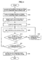
- Fig. 4 is a flow chart for explaining the operation of the radio communication equipment.
- the radio communication equipment searches for one or more possible parties at the other end of radio communication connection (in step ST1), and displays the one or more possible parties with which the radio communication equipment can communication by radio on the display 1 based on the searching result (in step ST2).
- the radio communication equipment When the user then selects a desired party with which the radio communication equipment will communicate by radio by operating the operation button 2 (in step ST3), and the radio communication equipment starts carrying out radio communications with the selected party (in step ST4).
- the radio communication equipment decodes the received signal by using the sending and receiving circuit 5 and determines whether or not the level of the decoded received signal is greater than a predetermined value by using the received level determining circuit 6 (in step ST5).
- the radio communication equipment then delivers the determination result to the ⁇ computer 7 so as to check to see whether the determination result shows that the signal level of the decoded received signal is greater than the predetermined value (in step ST6), and further determines whether the radio communication processing has been finished when the determination result shows that the level of the decoded received signal is greater than the predetermined value (i.e., if YES as the result of performing ST6) (in step ST7).
- the radio communication equipment returns to step ST5 in which it repeats the measurement of the received signal level.
- step ST6 When the determination result of step ST6 shows that the measured received signal level is equal to or less than the predetermined value (i.e., if NO as the result of performing step ST6), the radio communication equipment carries out radio communication equipment adjustment (i.e., adjustment of a tilting angle of the panel 3 with respect to the main body 15 of radio communication equipment) (in step ST9). After adjusting the tilting angle of the panel 3 with respect to the main body 15, the radio communication equipment returns to step ST5 in which it measures the received signal level again. The radio communication equipment then, in step ST6, determines again whether or not the received signal level is greater than the predetermined value.
- radio communication equipment adjustment i.e., adjustment of a tilting angle of the panel 3 with respect to the main body 15 of radio communication equipment
- the sound signal When a sound signal generated by the microphone 16 is to be sent out through radio communications, the sound signal is passed through the sound signal processing circuit 10, the ⁇ computer 7, the sending and receiving circuit 5, and the antenna 4, and is then transmitted to the party at the other end of the radio communication connection.
- a sound signal from the party at the other end of the radio communication connection flows opposite in direction to the travel of the outgoing sound signal from the radio communication equipment and is then input to the sound signal processing circuit 10, and a reproduced sound is output from the speaker 17.
- the ⁇ computer 7 determines whether the user has performed a radio communication end operation by operating the operation button 2 or the sending and receiving circuit 5 has received a radio communication end signal indicating an instruction of ending the radio communication processing from the party at the other end of the radio communication connection. If YES as the result of performing step ST7, the ⁇ computer 7 returns the radio communication equipment to its original state (in step ST8), and then ends the sequence of radio communication operations.
- the TV signal processing circuit 11 processes a TV signal received by the TV antenna 18, and the video signal processing circuit 14 then generates a video signal, which conforms to the display 1, from the processed TV signal from the TV signal processing circuit 11.
- the medium drive mechanism 13 reads map data from a medium such as a DVD-ROM, and generates and delivers a map signal used for vehicle navigation to the navigation signal processing circuit 12, the navigation signal processing circuit 12 processes the map signal and the video signal processing circuit 14 generates a video signal which conforms to the display 1, from the processed map signal from the navigation signal processing circuit 12.
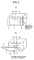
- Fig. 5 is an explanatory drawing showing the structure of a main body 15 of radio communication equipment in which an antenna 4 for sending and receiving electric waves for radio communication is mounted.
- an insertion opening 15a for cassette tapes and an insertion opening 15b for CDs are disposed in a front surface of the main body 15 of radio communication equipment.
- a lower edge of a panel 3 accommodating a display 1 in a frame 19 thereof is attached to the main body 15 of radio communication equipment by way of a hinge (not shown in the figure), for example, so that the panel 3 can cover the insertion openings 15a and 15b and can be opened and closed.
- the directivity pattern of the antenna 4 for radio communication accommodated in the opening and closing panel 3 mounted on the main body 15 of radio communication equipment is oriented in a direction of the front of the main body 15, the directivity pattern roughly confronts mobile equipment (not shown in the figure), which is put in a driver's breast pocket, for example, and good conditions must be therefore satisfied when the radio communication equipment communicates by radio with this mobile equipment (see Fig. 5(a)).
- the direction of the directivity pattern of the antenna 4 is not necessarily ideal.
- the radio communication equipment causes the panel opening and closing mechanism 9 to work based on an output signal of an antenna status adjusting circuit 8 that runs from an output of a ⁇ computer 7 that has processed an output of a received level determining circuit 6.
- a panel opening and closing mechanism 9 then tilts the panel 3 in a slightly-downward direction so that the directivity pattern of the antenna 4 is inclined in a direction of where the mobile equipment is located.
- the radio communication equipment can provide a good condition for radio communications (see Fig. 5(b)).
- the radio communication equipment can display the status of signals received from the party with which the radio communication equipment communicates by radio on the display 1 mounted in the panel 3. When the panel 3 moves, the radio communication equipment can also display the fact that the panel 3 moves on the display 1. As previously mentioned, the radio communication equipment can automatically adjust a tilting angle of the panel 3 attached to the main body 15 of radio communication equipment so that the panel 3 is oriented in a slightly-downward direction by activating the panel opening and closing mechanism 9 based on the output of the received level determining circuit 6 that determines the level of signals received from the party with which the radio communication equipment communicates by radio.
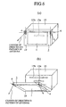
- Fig. 6 is an explanatory drawing showing the structure of a main body 15 of radio communication equipment in which an antenna 4 for sending and receiving electric waves for radio communication is mounted.
- the main body 15 of radio communication equipment is the one that is provided as an extension of that in accordance with embodiment 2 shown in Fig. 5, and is provided with two antennas 4 built in a panel 3 and having directivity patterns whose central directions are different from each other.
- Fig. 6 (a) is a state diagram showing the panel 3 which is closed
- Fig. 6(b) is a state diagram showing the panel 3 which is opened and inclined in a slightly-downward direction.
- Either a method of selectively using one of the two antennas 4 with a higher received signal level or a method of using the two antennas 4 and combining the levels of signals received by the two antennas 4 can be adopted. Consequently, the radio communication equipment can finely adjust a tilting angle of the panel with respect to the main body 15 of radio communication equipment according to the position of the party with which the radio communication equipment communicates by radio.
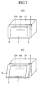
- Fig. 7 is an explanatory drawing showing the structure of a main body of radio communication equipment in which an antenna 4 for sending and receiving electric waves for radio communication is mounted.
- a panel 3 is slidably attached to a front side of the radio communication equipment 15 so that the panel can be opened or closed, and an antenna 4 is disposed in the main body of radio communication equipment so that it can be covered by the panel 3 when the panel is closed.
- the radio communication equipment in accordance with this embodiment 4 differs from the radio communication equipment in accordance with embodiment 2 as shown in Fig. 5 in that the antenna 4 is disposed in the main body 15 of radio communication equipment, and the other components of the radio communication equipment in accordance with embodiment 4 are the same as those of the radio communication equipment in accordance with embodiment 2.
- the radio communication equipment Under normal conditions, the radio communication equipment carries out radio communications with the panel 3 being closed, as shown in Fig. 7(a).
- the radio communication equipment automatically makes the panel 3 slightly slide, as shown in Fig. 7(b), so that a front side of the antenna 4 can be viewed from outside the main body of radio communication equipment and send/receive signals can be easily passed through the panel. Because the radio communication equipment makes the panel 3 slightly slide, the user can see information displayed on the display 1 in the panel 4 as before even in this state.
- Fig. 8 is an explanatory drawing showing the structure of a main body of radio communication equipment in which an antenna 4 for sending and receiving electric waves for radio communication is mounted.
- the main body of radio communication equipment is the one that is provided as an extension of that in accordance with embodiment 4 shown in Fig. 7. In this embodiment 5, as shown in Figs.
- the radio communication equipment when the deterioration of the received signal level is not improved even though the radio communication equipment automatically makes a panel 3 slide based on a result of determination from a received level determining circuit 6 so that the panel 3 is slightly opened with respect to the main body 15 of radio communication equipment, the radio communication equipment allows the user to connect an external antenna (not shown in the figure) with a connector 20 disposed in the main body 15 of radio communication equipment, so that the user can place the external antenna at an optimum position where the received signal level is improved and the radio communication equipment can properly carry out radio communications.
- an external antenna not shown in the figure
- Fig. 9 is an explanatory drawing showing the structure of a main body 15 of radio communication equipment in which an antenna 4 for sending and receiving electric waves for radio communication is mounted.
- a panel 3 is so formed as to have a size smaller than a size of a front side of the main body 15 of radio communication equipment.
- the radio communication equipment Under normal conditions, the radio communication equipment carries out radio communications by way of the antenna 4 built in the main body 15 of radio communication equipment, as shown in Fig. 9(a).
- the radio communication equipment allows the user to connect an external antenna 21 with a connector 20 disposed in the main body 15 of radio communication equipment, so that the user can place the external antenna 21 at an optimum position where the received signal level is improved and the radio communication equipment can properly carry out radio communications.
- an improvement in the received signal level can be obtained regardless of opening or closing of the panel 3 with respect to the main body 15 of radio communication equipment.
- the panel 3 When attaching or detaching a cassette tape or CD to or from the main body 15 of radio communication equipment, for example, the panel 3 is opened as shown in Fig. 9(b).
- Fig. 10 is an explanatory drawing showing the structure of a main body 15 of radio communication equipment in which an antenna 4 for sending and receiving electric waves for radio communication is mounted.
- This embodiment 7 is another example in which a panel 3 is so formed as to have a size smaller than a size of a front side of the main body 15 of radio communication equipment.
- a stretchable antenna 4a is placed in the main body 15 of radio communication equipment in the vicinity of a lateral side of the panel 3, as shown in Fig. 10(a).
- the radio communication equipment Under normal conditions, the radio communication equipment carries out radio communications with the stretchable antenna 4a being contracted, as shown in Fig. 10(a).
- the radio communication equipment allows the user to extend the antenna 4a, as shown in Fig. 10(b), based on a detection signal indicating the deterioration of the received signal level or operates a driving unit for driving the antenna, such as a motor (not shown in the figure), so as to automatically extend the stretchable antenna 4a, thereby improving the received signal level.
- a driving unit for driving the antenna such as a motor (not shown in the figure)
- the panel 3 When attaching or detaching a cassette tape or CD to or from the main body 15 of radio communication equipment, for example, the panel 3 is opened as shown in Fig. 10(b).
- the radio communication equipment of the present invention is applied to a vehicle-mounted navigation apparatus whose receiving status changes as the vehicle moves.
- the radio communication equipment of the present invention can be similarly applied to a TV set whose receiving status changes when it is moved to another installation place or when TV channel switching or the like is carried out.
- the radio communication equipment in accordance with the present invention is suitable for obtaining an improvement in the performance of short-distance radio communication equipment having a so-called Bluetooth communication function.
Landscapes
- Engineering & Computer Science (AREA)
- Computer Networks & Wireless Communication (AREA)
- Mobile Radio Communication Systems (AREA)
- Variable-Direction Aerials And Aerial Arrays (AREA)
- Support Of Aerials (AREA)
- Structure Of Receivers (AREA)
- Input Circuits Of Receivers And Coupling Of Receivers And Audio Equipment (AREA)
- Transceivers (AREA)
Abstract
Description
Claims (7)
- Radio communication equipment comprising: a reception status determining means for determining a received level of a signal received through radio communications; and a radio communication status adjusting means for automatically adjusting a radio communication status so that the radio communication status is optimum according to the received signal level determined by said reception status determining means.
- Radio communication equipment comprising: a panel provided with an antenna and tiltably mounted on a main body of radio communication equipment; a reception status determining means for determining a received level of a signal received through radio communications; and a tilting angle adjusting means for, when the received signal level determined by said reception status determining means is equal to or less than a predetermined value, automatically adjusting a tilting angle of said panel so that the received signal level is increased to a maximum.
- The radio communication equipment according to Claim 2, characterized in that said panel tiltably mounted on said main body of radio communication equipment is provided with a plurality of antennas having different directivities.
- Radio communication equipment comprising: an antenna disposed in a main body of radio communication equipment; a panel tiltably mounted on said main body of radio communication equipment so as to cover said antenna; a reception status determining means for determining a received level of a signal received by said antenna; and a tilting angle adjusting means for, when the received signal level determined by said reception status determining means is equal to or less than a predetermined value, opening said panel so that a front side of said antenna can be viewed from outside said main body of radio communication equipment.
- The radio communication equipment according to Claim 4, characterized in that said equipment includes an internal antenna disposed in the main body of said radio communication equipment and an external antenna; a reception status determining means for determining a received level of a signal received by said internal antenna; and a display means for, when the received signal level determined by said reception status determining means is equal to or less than a predetermined value, opening said panel so that a front side of said internal antenna can be viewed from outside said main body, and for, when said reception status determining means determines that the received signal level is still equal to or less than the predetermined value after further radio communications are carried out, generating a display screen that urges use of said external antenna.
- The radio communication equipment according to Claim 5, characterized in that said equipment includes a connector disposed in part of said main body of said radio communication equipment, which is not covered by said panel, for connecting with said internal and external antennas.
- The radio communication equipment according to Claim 5, characterized in that said equipment includes a stretchable antenna disposed in part of said main body of said radio communication equipment, which is not covered by said panel.
Applications Claiming Priority (1)
| Application Number | Priority Date | Filing Date | Title |
|---|---|---|---|
| PCT/JP2002/001044 WO2003067771A1 (en) | 2002-02-07 | 2002-02-07 | Radio communication apparatus |
Publications (3)
| Publication Number | Publication Date |
|---|---|
| EP1473840A1 true EP1473840A1 (en) | 2004-11-03 |
| EP1473840A4 EP1473840A4 (en) | 2005-03-09 |
| EP1473840B1 EP1473840B1 (en) | 2007-04-18 |
Family
ID=27677650
Family Applications (1)
| Application Number | Title | Priority Date | Filing Date |
|---|---|---|---|
| EP02711383A Expired - Lifetime EP1473840B1 (en) | 2002-02-07 | 2002-02-07 | Radio communication apparatus |
Country Status (6)
| Country | Link |
|---|---|
| US (1) | US7389127B2 (en) |
| EP (1) | EP1473840B1 (en) |
| JP (1) | JP3884014B2 (en) |
| CN (1) | CN1271792C (en) |
| DE (1) | DE60219694T2 (en) |
| WO (1) | WO2003067771A1 (en) |
Families Citing this family (8)
| Publication number | Priority date | Publication date | Assignee | Title |
|---|---|---|---|---|
| JP4070745B2 (en) * | 2004-05-21 | 2008-04-02 | 三洋電機株式会社 | Broadcast receiving mobile terminal |
| KR100689544B1 (en) | 2004-10-23 | 2007-03-02 | 삼성전자주식회사 | Apparatus and method for selecting an antenna in a digital broadcast receiving terminal |
| US7616977B1 (en) * | 2005-01-28 | 2009-11-10 | Scott David Nortman | Method and apparatus for motorized control of an automobile radio cover |
| JP4747628B2 (en) * | 2005-03-28 | 2011-08-17 | 日産自動車株式会社 | Automotive antenna |
| US7535426B2 (en) * | 2005-06-20 | 2009-05-19 | Visteon Global Technologies, Inc. | Integrated antenna in display or lightbox |
| JP4547539B2 (en) * | 2006-03-06 | 2010-09-22 | アルパイン株式会社 | AV equipment and control method thereof |
| US8259684B1 (en) * | 2008-10-30 | 2012-09-04 | Clearwire Ip Holdings Llc | Seasonality optimization of wireless networks |
| CN101605403A (en) * | 2009-07-14 | 2009-12-16 | 中兴通讯股份有限公司 | Signal receiving device and its implementation |
Family Cites Families (27)
| Publication number | Priority date | Publication date | Assignee | Title |
|---|---|---|---|---|
| US3671969A (en) * | 1970-01-30 | 1972-06-20 | Vefik A Basman | Automatic antenna alignment system for enabling maximum signal reception |
| US4939792A (en) * | 1987-11-16 | 1990-07-03 | Motorola, Inc. | Moldable/foldable radio housing |
| US4894663A (en) * | 1987-11-16 | 1990-01-16 | Motorola, Inc. | Ultra thin radio housing with integral antenna |
| JPH04372209A (en) | 1991-06-21 | 1992-12-25 | Alpine Electron Inc | On-vehicle radio receiver |
| JP3217408B2 (en) | 1991-11-21 | 2001-10-09 | 松下電工株式会社 | Planar antenna |
| JPH06225230A (en) | 1992-07-03 | 1994-08-12 | Shiro Sugimura | On-vehicle television broadcast receiver |
| JPH0653848A (en) | 1992-07-29 | 1994-02-25 | Tokyo Electric Co Ltd | Radio data receiving equipment |
| JPH06152489A (en) | 1992-11-13 | 1994-05-31 | Ai Takagi | Antenna system for mobile object |
| JP3290322B2 (en) | 1994-01-20 | 2002-06-10 | システム.ユニークス株式会社 | Tracking control system for mobile antenna |
| US5561436A (en) * | 1994-07-21 | 1996-10-01 | Motorola, Inc. | Method and apparatus for multi-position antenna |
| US5617102A (en) | 1994-11-18 | 1997-04-01 | At&T Global Information Solutions Company | Communications transceiver using an adaptive directional antenna |
| US5819185A (en) * | 1995-06-07 | 1998-10-06 | Hitachi, Ltd. | Portable satellite communication apparatus |
| US5734716A (en) * | 1995-09-29 | 1998-03-31 | Qualcomm Incorporated | Magnetically driven vertically correcting antenna for portable telephones |
| JPH09153850A (en) | 1995-11-30 | 1997-06-10 | Sharp Corp | Portable receiver |
| US5797083A (en) * | 1995-12-22 | 1998-08-18 | Hughes Electronics Corporation | Self-aligning satellite receiver antenna |
| US5809403A (en) * | 1996-03-11 | 1998-09-15 | Erisson Inc. | Coaxial cable assembly for a portable phone |
| JPH09261749A (en) | 1996-03-26 | 1997-10-03 | Sony Corp | Automotive electronics |
| JPH10126286A (en) | 1996-10-23 | 1998-05-15 | Toshiba Corp | Receiver with ferrite bar antenna |
| KR100245626B1 (en) * | 1997-06-30 | 2000-02-15 | 강병호 | Keyboard tilting device for portable computer |
| JPH11186947A (en) * | 1997-12-22 | 1999-07-09 | Uniden Corp | Portable communication terminal device |
| JP2000015142A (en) | 1998-07-01 | 2000-01-18 | Tomy Seiko:Kk | Centrifugal separator |
| JP2000151452A (en) * | 1998-11-06 | 2000-05-30 | Kokusai Electric Co Ltd | Portable wireless terminal device |
| KR100273647B1 (en) | 1998-11-23 | 2000-12-15 | 윤종용 | Artificial intelligence antenna driving apparatus and control method thereof |
| KR20010073841A (en) * | 2000-01-21 | 2001-08-03 | 서평원 | Method and device for auto controlling antenna in mobile station |
| US6603425B1 (en) * | 2000-09-22 | 2003-08-05 | Rockwell Collins, Inc. | Method and system for suppressing ground clutter returns on an airborne weather radar |
| US6778844B2 (en) * | 2001-01-26 | 2004-08-17 | Dell Products L.P. | System for reducing multipath fade of RF signals in a wireless data application |
| US6653981B2 (en) * | 2001-11-01 | 2003-11-25 | Tia Mobile, Inc. | Easy set-up, low profile, vehicle mounted, satellite antenna |
-
2002
- 2002-02-07 US US10/472,480 patent/US7389127B2/en not_active Expired - Fee Related
- 2002-02-07 CN CNB028077660A patent/CN1271792C/en not_active Expired - Fee Related
- 2002-02-07 DE DE60219694T patent/DE60219694T2/en not_active Expired - Lifetime
- 2002-02-07 JP JP2003566994A patent/JP3884014B2/en not_active Expired - Fee Related
- 2002-02-07 WO PCT/JP2002/001044 patent/WO2003067771A1/en not_active Ceased
- 2002-02-07 EP EP02711383A patent/EP1473840B1/en not_active Expired - Lifetime
Also Published As
| Publication number | Publication date |
|---|---|
| EP1473840A4 (en) | 2005-03-09 |
| DE60219694T2 (en) | 2007-12-27 |
| CN1500310A (en) | 2004-05-26 |
| JP3884014B2 (en) | 2007-02-21 |
| DE60219694D1 (en) | 2007-05-31 |
| JPWO2003067771A1 (en) | 2005-06-02 |
| US7389127B2 (en) | 2008-06-17 |
| CN1271792C (en) | 2006-08-23 |
| EP1473840B1 (en) | 2007-04-18 |
| US20040104855A1 (en) | 2004-06-03 |
| WO2003067771A1 (en) | 2003-08-14 |
Similar Documents
| Publication | Publication Date | Title |
|---|---|---|
| US7800553B2 (en) | Information processing apparatus with antenna switching function, communication apparatus, antenna switching control unit, antenna switching control program, and computer-readable recording medium recording the same program | |
| US7424308B2 (en) | Mobile terminal device and antenna switch | |
| US20140044277A1 (en) | Wireless audio transmission system, receiver, video camera and audio mixer | |
| US7085538B2 (en) | Portable communication terminal with image transmission function | |
| EP1473840A1 (en) | Radio communication apparatus | |
| JP2005094532A (en) | Mobile terminal | |
| KR100610187B1 (en) | High-frequency receiving unit and high-frequency receiving method | |
| EP1662605A1 (en) | FM transmission antenna device in a portable terminal | |
| JP2003163956A (en) | Portable radio | |
| JP2005295312A (en) | Portable wireless device | |
| JP2003163529A (en) | Headphone serving as diversity antenna | |
| KR20010053811A (en) | Handsfree appratus utilizing car audio apparatus for mobile phone | |
| JP2877207B2 (en) | Satellite communication terminal with detachable handset cradle | |
| US20070021079A1 (en) | Wireless electronic device and method for controlling the wireless electronic device | |
| KR20040023331A (en) | Hands free apparatus for vehicle | |
| JP4265651B2 (en) | Mobile device | |
| JP2002290544A (en) | Portable wireless terminal | |
| JP2001177635A (en) | Intercom equipment | |
| JP2007288593A (en) | Cradle and electronic equipment | |
| JP2004072771A (en) | Portable transmitting and / or receiving device | |
| US20020103000A1 (en) | Mobile station, communication system, and transmission method | |
| JP4064683B2 (en) | Car radio | |
| KR20050019627A (en) | Apparatus and method for controlling antenna according to the degree of electric field in mobile communication terminal | |
| KR100655680B1 (en) | Control method of earphone device of portable wireless terminal | |
| JP2001086046A (en) | Portable telephone system with camera |
Legal Events
| Date | Code | Title | Description |
|---|---|---|---|
| PUAI | Public reference made under article 153(3) epc to a published international application that has entered the european phase |
Free format text: ORIGINAL CODE: 0009012 |
|
| 17P | Request for examination filed |
Effective date: 20030917 |
|
| AK | Designated contracting states |
Kind code of ref document: A1 Designated state(s): AT BE CH CY DE DK ES FI FR GB GR IE IT LI LU MC NL PT SE TR |
|
| A4 | Supplementary search report drawn up and despatched |
Effective date: 20050121 |
|
| RIC1 | Information provided on ipc code assigned before grant |
Ipc: 7H 01Q 1/32 B Ipc: 7H 01Q 21/28 B Ipc: 7H 04B 1/08 A Ipc: 7H 01Q 1/22 B |
|
| RAP1 | Party data changed (applicant data changed or rights of an application transferred) |
Owner name: MITSUBISHI DENKI KABUSHIKI KAISHA |
|
| GRAP | Despatch of communication of intention to grant a patent |
Free format text: ORIGINAL CODE: EPIDOSNIGR1 |
|
| RIN1 | Information on inventor provided before grant (corrected) |
Inventor name: NOMIYAMA, YASUHIKOC/O MITSUBISHI DENKI KABUSHIKI Inventor name: MIYAZAKI, HIDETOC/O MITSUBISHI DENKI KABUSHIKI |
|
| GRAS | Grant fee paid |
Free format text: ORIGINAL CODE: EPIDOSNIGR3 |
|
| GRAA | (expected) grant |
Free format text: ORIGINAL CODE: 0009210 |
|
| AK | Designated contracting states |
Kind code of ref document: B1 Designated state(s): DE |
|
| REF | Corresponds to: |
Ref document number: 60219694 Country of ref document: DE Date of ref document: 20070531 Kind code of ref document: P |
|
| PLBE | No opposition filed within time limit |
Free format text: ORIGINAL CODE: 0009261 |
|
| STAA | Information on the status of an ep patent application or granted ep patent |
Free format text: STATUS: NO OPPOSITION FILED WITHIN TIME LIMIT |
|
| 26N | No opposition filed |
Effective date: 20080121 |
|
| REG | Reference to a national code |
Ref country code: DE Ref legal event code: R084 Ref document number: 60219694 Country of ref document: DE Effective date: 20110706 Ref country code: DE Ref legal event code: R084 Ref document number: 60219694 Country of ref document: DE Effective date: 20110506 |
|
| PGFP | Annual fee paid to national office [announced via postgrant information from national office to epo] |
Ref country code: DE Payment date: 20140417 Year of fee payment: 13 |
|
| REG | Reference to a national code |
Ref country code: DE Ref legal event code: R119 Ref document number: 60219694 Country of ref document: DE |
|
| PG25 | Lapsed in a contracting state [announced via postgrant information from national office to epo] |
Ref country code: DE Free format text: LAPSE BECAUSE OF NON-PAYMENT OF DUE FEES Effective date: 20150901 |