EP1473602A1 - Method and device for cleaning liquid development electrophotographic device - Google Patents
Method and device for cleaning liquid development electrophotographic device Download PDFInfo
- Publication number
- EP1473602A1 EP1473602A1 EP03701895A EP03701895A EP1473602A1 EP 1473602 A1 EP1473602 A1 EP 1473602A1 EP 03701895 A EP03701895 A EP 03701895A EP 03701895 A EP03701895 A EP 03701895A EP 1473602 A1 EP1473602 A1 EP 1473602A1
- Authority
- EP
- European Patent Office
- Prior art keywords
- liquid
- cleaning
- intermediate transfer
- transfer member
- developer
- Prior art date
- Legal status (The legal status is an assumption and is not a legal conclusion. Google has not performed a legal analysis and makes no representation as to the accuracy of the status listed.)
- Withdrawn
Links
Images






Classifications
-
- G—PHYSICS
- G03—PHOTOGRAPHY; CINEMATOGRAPHY; ANALOGOUS TECHNIQUES USING WAVES OTHER THAN OPTICAL WAVES; ELECTROGRAPHY; HOLOGRAPHY
- G03G—ELECTROGRAPHY; ELECTROPHOTOGRAPHY; MAGNETOGRAPHY
- G03G15/00—Apparatus for electrographic processes using a charge pattern
- G03G15/14—Apparatus for electrographic processes using a charge pattern for transferring a pattern to a second base
- G03G15/16—Apparatus for electrographic processes using a charge pattern for transferring a pattern to a second base of a toner pattern, e.g. a powder pattern, e.g. magnetic transfer
- G03G15/1605—Apparatus for electrographic processes using a charge pattern for transferring a pattern to a second base of a toner pattern, e.g. a powder pattern, e.g. magnetic transfer using at least one intermediate support
- G03G15/161—Apparatus for electrographic processes using a charge pattern for transferring a pattern to a second base of a toner pattern, e.g. a powder pattern, e.g. magnetic transfer using at least one intermediate support with means for handling the intermediate support, e.g. heating, cleaning, coating with a transfer agent
-
- G—PHYSICS
- G03—PHOTOGRAPHY; CINEMATOGRAPHY; ANALOGOUS TECHNIQUES USING WAVES OTHER THAN OPTICAL WAVES; ELECTROGRAPHY; HOLOGRAPHY
- G03G—ELECTROGRAPHY; ELECTROPHOTOGRAPHY; MAGNETOGRAPHY
- G03G21/00—Arrangements not provided for by groups G03G13/00 - G03G19/00, e.g. cleaning, elimination of residual charge
- G03G21/0088—Arrangements not provided for by groups G03G13/00 - G03G19/00, e.g. cleaning, elimination of residual charge removing liquid developer
-
- G—PHYSICS
- G03—PHOTOGRAPHY; CINEMATOGRAPHY; ANALOGOUS TECHNIQUES USING WAVES OTHER THAN OPTICAL WAVES; ELECTROGRAPHY; HOLOGRAPHY
- G03G—ELECTROGRAPHY; ELECTROPHOTOGRAPHY; MAGNETOGRAPHY
- G03G2215/00—Apparatus for electrophotographic processes
- G03G2215/01—Apparatus for electrophotographic processes for producing multicoloured copies
- G03G2215/0103—Plural electrographic recording members
-
- G—PHYSICS
- G03—PHOTOGRAPHY; CINEMATOGRAPHY; ANALOGOUS TECHNIQUES USING WAVES OTHER THAN OPTICAL WAVES; ELECTROGRAPHY; HOLOGRAPHY
- G03G—ELECTROGRAPHY; ELECTROPHOTOGRAPHY; MAGNETOGRAPHY
- G03G2215/00—Apparatus for electrophotographic processes
- G03G2215/16—Transferring device, details
- G03G2215/1647—Cleaning of transfer member
- G03G2215/1661—Cleaning of transfer member of transfer belt
Definitions
- the present invention relates to a cleaning method and a cleaning apparatus for a liquid-development electrophotographic apparatus which uses a liquid developer (liquid toner), and particularly to a cleaning method and a cleaning apparatus for a liquid-development electrophotographic apparatus which are capable of effectively and stably cleaning off residual developer (residual toner) that coheres and firmly adheres to an intermediate transfer member.
- FIG. 11 shows a conceptual configuration of a conventional liquid-development electrophotographic apparatus.
- the conventional liquid-development electrophotographic apparatus has an intermediate transfer member 51 formed of a roller which is rotated at a predetermined speed; and a backup roller 59 which is in press contact with the intermediate transfer member 51 and is rotated such that a contact portion of the backup roller 59 and a contact portion of the intermediate transfer member 51 move in the same direction.
- An image formed of liquid toner on the surface of the intermediate transfer member 51 is transferred to a printing medium 60, which is moved while being nipped between the intermediate transfer member 51 and the backup roller 59.
- An image to be transferred to the printing medium 60 from the intermediate transfer member 51 consists of a yellow element image, which is in yellow toner and transfer-supplied from a developing unit 54; a red element image, which is in red toner and transfer-supplied from a developing unit 55; a blue element image, which is in blue toner and transfer-supplied from a developing unit 56; and a black element image, which is in black toner and transfer-supplied from a developing unit 57.
- the developing unit 54 which transfer-supplies a yellow element image to the intermediate transfer member 51, includes a toner supply pot 54d for storing a yellow liquid toner; a pattern roller 54c for taking out the liquid toner from the toner supply pot 54d; a developing roller 54b for leveling the liquid toner supplied from the pattern roller 54c so as to form a toner layer of uniform thickness; and a photoconductor drum 54a for forming a yellow element image by use of the toner layer transfer-supplied from the developing roller 54b.
- the yellow liquid toner stored in the toner supply pot 54d is supplied in a state of including a carrier, which is a nonvolatile liquid.
- the carrier which is a nonvolatile liquid, adheres to the surface of the intermediate transfer member 51 on which a yellow element image is formed.
- the intermediate transfer member 51 is similarly transfer-supplied with a red element image from the developing unit 55. Then, the intermediate transfer member 51 is sequentially transfer-supplied with a blue element image from the developing unit 56, and a black element image from the developing unit 57, thereby forming a color image as a whole.
- Each of the developing unit 55, the developing unit 56, and the developing unit 57 assumes a configuration similar to the aforementioned configuration of the yellow-related developing unit 54. Accordingly, a color image is formed on the surface of the intermediate transfer member 51 by means of yellow liquid toner, red liquid toner, blue liquid toner, and black liquid toner; and a carrier contained in the color toners adheres to the surface of the intermediate transfer member 51.
- the surface of the photoconductor drum associated with each of the colors is equipped with, for example, an image formation mechanism for electrostatically forming a latent image, and an accessory mechanism therefor; a mechanism for eliminating static electricity from the surface of the photoconductor drum after transfer-supply of the corresponding element image to the intermediate transfer member 51; and a mechanism for removing residual toner.
- the carrier-removing unit 58 When an image formed on the surface of the intermediate transfer member 51 passes a position of contact with a carrier-removing unit 58, the carrier is removed from the image. Then, the image ⁇ which is formed of the color toners ⁇ is transferred to the printing medium 60, which moves while being nipped under pressure between the backup roller 59 and the intermediate transfer member 51. The image transferred to the printing medium 60 is fixed in a fixing unit (not shown).
- a portion of the intermediate transfer member 51 on which an image is previously formed reaches the position of a cleaning unit 52.
- the cleaning unit 52 removes residues of toner (hereinafter, called “residual toner” or “residual developer”), whereby the intermediate transfer member 51 prepares for a next cycle of forming images in the corresponding colors by means of the developing units 54, 55, 56, and 57.
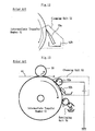
- the conventional cleaning unit 52 shown in FIG. 11 will be described in detail with reference to FIG. 12.
- the cleaning unit 52 includes a blade 52a which is in press contact with the intermediate transfer member 51, and a residual-toner pot 52b.
- the blade 52a scrapes off residual toner of firm adhesion from the surface of the intermediate transfer member 51, thereby collecting the residual toner in the residual-toner pot 52b.
- FIG. 13 shows another conventional cleaning unit.
- the cleaning unit 52 includes an electrically conductive elastic-body roller 62a in press contact with the intermediate transfer member 51, and an elastic cleaning blade 62b disposed downstream of the roller 62a.
- the electrically conductive elastic-body roller 62a is grounded, or a bias voltage opposite in polarity to an electrostatic latent image is applied to the electrically conductive elastic-body roller 62a.
- a bias voltage polarized in such a direction as to cause exfoliation of residual toner is applied between the electrically conductive elastic-body roller 62a and the intermediate transfer member 51 to thereby exfoliate from the intermediate transfer member 51 residual toner-which coheres/firmly adheres to the intermediate transfer member 51.
- the elastic cleaning blade 62b is adapted to remove, from the intermediate transfer member 51, the residual toner which is exfoliated from the intermediate transfer member 51 by means of the elastic-body roller 62a.
- a 4-color image formed on the intermediate transfer member 51 is not entirely transferred to a printing medium.
- Residual developer (residual toner) which remains on the intermediate transfer member 51 without being transferred to the printing medium is removed in a period of time ranging from the end of a transfer process in which the intermediate transfer member 51 makes one rotation to thereby transfer a toner image to the printing medium, to the start of a subsequent process in which a toner image is transferred from a photoconductor drum to the intermediate transfer member 51.
- the residual developer is removed by means of the cleaning unit located upstream of the developing unit 54 and downstream of the backup roller 59, which is disposed in opposition to the intermediate transfer member 51 provided for transferring a toner image to the printing medium.
- residual toner which the cleaning unit 52 has failed to collect gradually accumulates and begins to mix in an image formed on the surface of the intermediate transfer member 51, thereby affecting the quality of an image which the intermediate transfer member 51 forms.
- a cleaning operation as residual toner.
- the cleaning operation must handle a large amount of residual toner.
- the operation mode of the liquid-development electrophotographic apparatus must be changed over to a cleaning mode for removing residual toner.
- an operator changes over the operation mode of the apparatus to a cleaning mode and causes the apparatus to perform the cleaning operation a predetermined number of times, thereby preventing deterioration in the quality of an image formed by means of the intermediate transfer member 51.
- FIGS. 14 and 15 A configuration required for description of a control procedure will be described with reference to the block diagram of FIG. 14.
- An arithmetic control section B50 contained in a liquid-development electrophotographic apparatus B05 fetches a required program segment from a control program stored in a control program section B58 and executes a predetermined control procedure.
- a printing drive section B51 includes a drive system for driving the intermediate transfer member 51, and a press-contact drive system for driving the backup roller 59.
- An image formation section B52 includes drive systems for driving the corresponding developing units 54, 55, 56, and 57, and a drive system for driving the carrier-removing unit 58.
- An error detection section B55 reports to the arithmetic control section B50 signals obtained from various error detection sensors disposed in the liquid-development electrophotographic apparatus B05.
- a printing control section B56a specifies an operation which the printing drive section B51 is to perform, timing of performing the operation, and the like; and a development control section B56b specifies an operation which the image formation section B52 is to perform, timing of performing the operation, and the like.
- Control procedure will be described with reference to the flowchart of FIG. 15.
- the liquid-development electrophotographic apparatus B05 indicates necessity to perform cleaning.
- the degree of contamination of the intermediate transfer member depends on the contents of an image which the liquid-development electrophotographic apparatus B05 forms.
- an operator must monitor the conditions of printing media ejected from the liquid-development electrophotographic apparatus B05 and set an appropriate timing of performing cleaning.
- Step S51 the operator selects a cleaning mode as an operation mode of the liquid-development electrophotographic apparatus B05. This causes the arithmetic control section B50 to fetch a program segment associated with the cleaning mode from the control program section B58 and to execute the program segment.
- Step S52 the development control section B56b retreats the image formation section B52. Specifically, this retreat operation causes the developing units 54, 55, 56, and 57 and the carrier-removing unit 58 to separate from the intermediate transfer member 51.
- Step S53 the printing control section B56a retreats the printing drive section B51. Specifically, this retreat operation causes the backup roller 59 to separate from the intermediate transfer member 51.
- Step S54 the arithmetic control section B50 starts a cleaning operation. Specifically, in this cleaning operation, the intermediate transfer member 51 rotates for a predetermined period of time while remaining in contact with the cleaning unit 52.
- Step S55 the arithmetic control section B50 ends the cleaning operation. Then, proceeding to Step S56, the arithmetic control section B50 cancels the retreat operation of the image formation section B52 and the retreat operation of the printing drive section B51 performed for the cleaning mode. Then, proceeding to Step S57, the arithmetic control section B50 stands by in preparation for the subsequent image formation mode.
- a carrier liquid which is a liquid component of a liquid developer, must be appropriately removed from the liquid developer (toner image) transferred to the intermediate transfer member.
- toner solids toner containing pigment or dye contained in the liquid developer cohere/firmly adhere to the intermediate transfer member.
- Residual developer which remains on the intermediate transfer member without being transferred to the printing medium coheres/firmly adheres to the intermediate transfer member in a stubborn manner.
- the liquid developer is heated to a temperature equal to or higher than the softening point of toner solids (resin containing pigment or dye) contained in the liquid developer, and is subjected to high pressure. Accordingly, residual developer which remains on the intermediate transfer member without being transferred to the printing medium coheres/firmly adheres to the intermediate transfer member in a stubborn manner.
- the present invention has been accomplished in view of the foregoing, and an object of the invention is to effectively and stably clean off residual developer which coheres/firmly adheres to the intermediate transfer member in a stubborn manner, when a liquid-development electrophotographic apparatus using a liquid developer performs cleaning.
- another object of the present invention is to construct a foundation for optimally setting cleaning conditions for different degrees of contamination of the intermediate transfer member through performance of a cleaning operation suited for the details of an error arising in the liquid-development electrophotographic apparatus.
- a cleaning liquid is applied to the intermediate transfer member which has transferred an image to the printing medium, to thereby weaken cohesion/firm adhesion of residual developer to the intermediate transfer member and again liquefy the residual developer cohering/firmly adhering to the intermediate transfer member. Furthermore, in order to exfoliate residual developer, which coheres/firmly adheres to the intermediate transfer member, from the intermediate transfer member, a bias voltage is applied to the intermediate transfer member. The residual developer exfoliated from the intermediate transfer member is collected together with the cleaning liquid.
- a cleaning method of the present invention for a liquid-development electrophotographic apparatus using a liquid developer comprises a cleaning-liquid application step of applying a cleaning liquid to the intermediate transfer member which has transferred an image to the printing medium; a bias voltage application step of applying, to the intermediate transfer member, a bias voltage opposite in polarity to charged toner particles of the residual developer (a bias voltage polarized in such a direction as to cause exfoliation of the developer); and a collection step of removing, from the intermediate transfer member, the cleaning liquid which has been applied in the cleaning-liquid application step, and the residual developer which remains on the intermediate transfer member without transfer of an image to the printing medium, and collecting the removed cleaning liquid and residual developer.
- a cleaning apparatus of the present invention for a liquid-development electrophotographic apparatus using a liquid developer is configured such that a cleaning unit for removing residual developer from the intermediate transfer member is disposed upstream of a developing unit and downstream of a backup roller, which is disposed in opposition to the intermediate transfer member so as to transfer a toner image to a printing medium.
- This cleaning unit comprises a cleaning-liquid application mechanism for applying a cleaning liquid to the intermediate transfer member which has transferred an image to the printing medium; a bias voltage application mechanism for applying, to the intermediate transfer member, a bias voltage opposite in polarity to charged toner particles of the developer (a bias voltage polarized in such a direction as to cause exfoliation of the developer); and a collection mechanism for removing, from the intermediate transfer member, the cleaning liquid which has been applied by means of the cleaning-liquid application mechanism, and the residual developer which remains on the intermediate transfer member without transfer of an image to the printing medium, and collecting the removed cleaning liquid and residual developer.
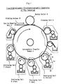
- FIG. 1 is a conceptual view showing the configuration of a liquid-development electrophotographic apparatus including a first example of a cleaning apparatus to which the present invention is applied.
- the liquid-development electrophotographic apparatus includes an intermediate transfer member 1 which is rotated at a predetermined speed and assumes a roller shape; and a backup roller 9 which is in press contact with the intermediate transfer member 1 and is rotated such that a contact portion of the backup roller 9 and a contact portion of the intermediate transfer member 1 move in the same direction.
- An image formed of liquid toner on the surface of the intermediate transfer member 1 is transferred to a printing medium 10, which is moved while being nipped between the intermediate transfer member 1 and the backup roller 9.
- An image to be transferred to the printing medium 10 from the intermediate transfer member 1 consists of a yellow element image, which is in yellow toner and transfer-supplied from a developing unit 4; a red element image, which is in red toner and transfer-supplied from a developing unit 5; a blue element image, which is in blue toner and transfer-supplied from a developing unit 6; and a black element image, which is in black toner and transfer-supplied from a developing unit 7.
- the developing unit 4 which transfer-supplies a yellow element image to the intermediate transfer member 1, includes a toner supply pot 4d for storing yellow liquid toner; a pattern roller 4c for taking out the liquid toner from the toner supply pot 4d; a developing roller 4b for leveling the liquid toner supplied from the pattern roller 4c so as to form a toner layer of uniform thickness; and a photoconductor drum 4a for forming a yellow element image by use of the toner layer transfer-supplied from the developing roller 4b.
- the surface of the photoconductor drum 4a is equipped with, for example, an image formation mechanism for electrostatically forming a latent image, along with an accessory mechanism therefor; a mechanism for eliminating static electricity from the surface of the photoconductor drum 4a after transfer-supply of a yellow element image to the intermediate transfer member 1; and a mechanism for removing residual toner.
- the yellow liquid toner stored in the toner supply pot 4d is supplied in a state including a carrier, which is a nonvolatile liquid.
- the carrier which is a nonvolatile liquid, adheres to the surface of the intermediate transfer member 1 on which a yellow element image is formed.
- the intermediate transfer member 1 is transfer-supplied with a red element image from the developing unit 5. Then, the intermediate transfer member 1 is sequentially transfer-supplied with a blue element image from the developing unit 6, and a black element image from the developing unit 7, thereby forming a color image as a whole.
- Each of the developing units 5, 6, and 7 assumes a configuration similar to the aforementioned configuration of the developing unit 4. Accordingly, an image is formed on the surface of the intermediate transfer member 1 by means of yellow liquid toner, red liquid toner, blue liquid toner, and black liquid toner; and the carrier contained in the color toners adheres to the surface of the intermediate transfer member 1.
- the carrier-removing unit 8 When an image formed on the surface of the intermediate transfer member 1 passes a position of contact with a carrier-removing unit 8, the carrier is separated and removed from the image. Then, the image, formed of the color toners, is transferred to the printing medium 10, which moves while being nipped under pressure between the backup roller 9 and the intermediate transfer member 1.
- the carrier-removing unit 8 is adapted to remove a carrier oil contained in an image which is formed on the intermediate transfer member 1 by means of liquid toners.
- the image transferred to the printing medium 10 is fixed in a fixing unit (not shown).
- the above-described liquid-development electrophotographic apparatus can be configured to have a structure similar to a conventionally known structure, or the structure described previously with reference to FIG. 11, except for the structure of the cleaning unit 2.
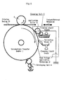
- FIG. 2 is a view showing the details of the cleaning unit 2 shown in FIG. 1.
- Residual developer which remains on the intermediate transfer member 1 without being transferred to a printing medium must be removed in a period to time ranging from the end of a transfer process in which the intermediate transfer member 1 makes one rotation to thereby transfer a toner image to the printing medium, to the start of a subsequent process in which a toner image is transferred from the photoconductor drum of the developing unit 4 to the intermediate transfer member 1.
- the cleaning unit 2 is located upstream of the developing unit 4 and downstream of the backup roller 9, which is disposed in opposition to the intermediate transfer member 1 provided for transferring a toner image to the printing medium.
- the cleaning unit 2 includes an application friction roller 21 and a bias roller 24, each of which presses the intermediate transfer member 1 at a predetermined pressure and is rotated in such a manner as to move at variable speed in an opposite direction with respect to movement of the intermediate transfer member 1.
- the expression "to move in opposite directions” means that mutually facing portions move in opposite directions. According to this definition, for example, when two rollers in contact with each other rotate in the same direction (for example, rotate clockwise), contact portions of the rollers move in mutually opposite directions.
- the application friction roller 21 also has a function to apply a shear force to residual toner so as to exfoliate and disperse the residual toner in a cleaning liquid.
- the bias roller 24 includes a bias voltage generation mechanism 24a for applying a bias voltage between the bias roller 24 and the intermediate transfer member 1.
- the bias roller 24 has a function to weaken the force of adhesion of residual toner firmly adhering to the surface of the intermediate transfer member 1 through application of a bias voltage to the intermediate transfer member 1; to exfoliate the residual toner of weakened adhesion from the intermediate transfer member 1; and to disperse the exfoliated residual toner in a cleaning liquid.
- a collection blade 25 has the function to collect the thus-exfoliated, dispersed residual toner.
- the application friction roller 21, intermediate rollers 22a and 22b, and a first pot 23 constitute an application mechanism for applying a cleaning liquid to the intermediate transfer member 1.
- the cleaning liquid is a substance substantially equal to a carrier liquid contained in a liquid toner used to form an image on the intermediate transfer member 1.
- a nonvolatile liquid such as silicone oil is used as the cleaning liquid.
- a cleaning liquid stored in the first pot 23 is taken out in such a manner as to adhere to the surface of the first intermediate roller 22b, which is rotated while being immersed in the stored cleaning liquid.
- the cleaning liquid is transferred to the surface of the application friction roller 21 via the second intermediate roller 22a.
- the cleaning liquid which is transferred and adheres to the surface of the application friction roller 21 is transferred to the surface of the intermediate transfer member 1.
- the cleaning liquid transferred to the surface of the intermediate transfer member 1 is a substance substantially equal to a carrier liquid.
- the cleaning liquid infiltrates into residual toner that firmly adheres to the surface of the intermediate transfer member 1, thereby weakening the force of adhesion of the residual toner.
- the application friction roller 21 and the intermediate transfer member 1 move in mutually opposite directions.
- residual toner firmly adhering to the surface of the intermediate transfer member 1 is subjected to a shear force which is induced by a frictional force of the application friction roller 21 and acts along the surface of the intermediate transfer member 1.
- the shear force induced by the frictional force of the application friction roller 21 and imposed on residual toner functions as a force of canceling the force of adhesion of the residual toner firmly adhering to the surface of the intermediate transfer member 1 to thereby exfoliate the residual toner from the intermediate transfer member 1.
- the residual toner exfoliated, by this shear force, from the surface of the intermediate transfer member 1 is dispersed in the cleaning liquid supplied from the application friction roller 21.
- the application friction roller 21 has a function to apply a cleaning liquid and a function to exfoliate residual toner through friction against the residual toner and disperse the residual toner in the cleaning liquid.
- the application friction roller 21, the intermediate roller 22a, and the intermediate roller 22b can be configured in such a manner as to be rotated at variable speed. For example, when the rotational speed of the application friction roller 21 in contact with the surface of the intermediate transfer member 1 is increased, the surface area of the application friction roller 21 in sliding contact with a unit area of the surface of the intermediate transfer member 1 increases, and thus the quantity of friction and the quantity of cleaning liquid transferring from the surface of the application friction roller 21 to the surface of the intermediate transfer member 1 increase. In other words, the capability to exfoliate and disperse residual toner can be controlled through control of the rotational speed of the application friction roller 21 and the intermediate rollers 22a and 22b.
- An outlet portion (distal end) of a drain mechanism 27 is located at height D above the bottom surface of the first pot 23.
- a supply port portion (distal end) of a reflux mechanism 28, which will be described later, is located above the liquid surface of the first pot 23.
- the maximum drain rate of the drain mechanism 27 is set higher than the maximum supply rate of the reflux mechanism 28. Through employment of this setting, the level of a cleaning liquid stored in the first pot 23 does not exceed a predetermined height (i.e., height D above the bottom surface) and does not drop below this predetermined height D.
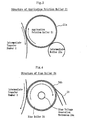
- a surface layer 21a is formed on the surface of the application friction roller 21.
- the surface layer 21a is formed of a resin-material or rubber-material foam or a member (nonwoven fabric, felt, or the like) made of fine fiber.
- the application friction roller 21 transfers a cleaning liquid-which is transferred to the application friction roller 21 from the intermediate roller 22a ⁇ to the intermediate transfer member 1, the application friction roller 21 holds the cleaning liquid in pits of the surface layer 21a formed of a foam or fine fiber and stably applies the cleaning liquid; and projections of the surface layer 21a impose a shear force on residual toner firmly adhering to the intermediate transfer member 1, by means of a frictional force generated through continuous sliding of the projections.
- the bias roller 24 and its peripheral structures will be described in terms of configuration, action, and effect.
- the bias roller 24, the blade 25, and a second pot 26 constitute a collection mechanism for collecting, from the surface of the intermediate transfer member 1, a cleaning liquid which contains residual toner in a dispersed condition.
- the surface of the bias roller 24 is in press contact with the surface of the intermediate transfer member 1 and moves in an opposite direction with respect to the surface of the intermediate transfer member 1; the bias roller 24 adsorbs residual toner through application of a bias voltage; and the bias roller 24 wipes off the cleaning liquid applied to the surface of the intermediate transfer member 1 to thereby collect the cleaning liquid. In so doing, residual toner dispersed in the cleaning liquid, together with the cleaning liquid, transfers from the surface of the intermediate transfer member 1 to the surface of the bias roller 24.
- the residual toner and the cleaning liquid transferred to the surface of the bias roller 24 is scraped together by means of the blade 25 in contact with the bias roller 24 and is collected in the second pot 26.
- the residual toner which, previously, firmly adheres to the intermediate transfer member 1 is collected, together with the cleaning liquid, in the second pot 26 via the bias roller 24.
- the bias roller 24 includes the bias voltage generation mechanism 24a, which applies a bias voltage between the bias roller 24 and the intermediate transfer member 1 located in opposition to the bias roller 24.
- This bias voltage weakens the force of adhesion of residual toner firmly adhering to the surface of the intermediate transfer member 1.
- the residual toner exfoliates from the intermediate transfer member 1; disperses in the cleaning liquid; and is adsorbed on the bias roller 24.
- the bias roller 24 has a function to collect residual toner and a function to exfoliate and disperse the residual toner by use of the bias voltage generation mechanism 24a.
- the reflux mechanism 28 is connected to the bottom of the second pot 26, which collects the cleaning liquid containing the residual toner dispersed therein.
- the reflux mechanism 28 transfers the cleaning liquid from the second pot 26 to the first pot 23 by means of a reflux pump 28a.
- the reflux mechanism 28 includes a cleaning-liquid regeneration mechanism 28c, which removes residual toner dispersing in the cleaning liquid so as to prevent deterioration of the cleaning liquid for reuse.
- the reflux pump 28a changes over the cleaning-liquid supply source to a replenishment mechanism 28b and transfers a new cleaning liquid to the first pot 23 from a replenishment pot (not shown) connected to the replenishment mechanism 28b.
- a surface resin layer 24b is formed on the bias roller 24.
- the surface roughness of the surface resin layer 24b is set such that a 10-point average roughness (Rz) is 3 ⁇ m or less. Through retainment of this surface roughness, appropriate smoothness is ensured to the surface of the bias roller 24, whereby the blade 25 in contact with the bias roller 24 can efficiently and stably scrape off a cleaning liquid.
- An electrical characteristic of the surface resin layer 24b formed on the surface of the bias roller 24 is set such that volume resistance substantially falls within a range of 10 k ⁇ to 10 G ⁇ . Through retainment of this volume resistance, the bias voltage generation mechanism 24a contained in the bias roller 24 can efficiently apply a bias voltage.
- the above-described cleaning unit employs a roller structure for the application friction roller 21 and the bias roller 24.
- a belt structure may be employed for the application friction roller 21 and/or the bias roller 24.
- rotary member means a structure in which continuously repetitive portions of a mobile member circulate and sequentially perform a predetermined operation, such as a structure implemented by the surface of, for example, such a roller or belt.
- FIG. 5 is a view showing a second example of a cleaning apparatus to which the present invention is applied.
- the cleaning unit 2 is located upstream of the developing unit 4 and downstream of the backup roller 9, which is disposed in opposition to the intermediate transfer member 1 provided for transferring a toner image to the printing medium 10.
- the cleaning unit 2 includes a cleaning-liquid application roller 11, a bias voltage application mechanism 12, and a collection blade 13.
- the cleaning unit 2 is configured in such a manner as to be able to come into contact with and retreat from the intermediate transfer member 1 by means of a contact/retreat mechanism.
- the cleaning-liquid application roller 11 applies a cleaning liquid to the intermediate transfer member 1 which has transferred an image to the printing medium 10.
- This cleaning-liquid application roller 11 is appropriately supplied with a cleaning liquid from a storage pot via an intermediate roller.
- the cleaning liquid applied by the cleaning-liquid application roller 11 is infiltrated into residual developer remaining on the intermediate transfer member 1 to thereby weaken cohesion/firm adhesion of residual developer to the intermediate transfer member 1 and again liquefies the residual developer cohering/firmly adhering to the intermediate transfer member.
- the bias voltage application mechanism 12 is adapted to apply, to the intermediate transfer member 1, a bias voltage opposite in polarity to charged toner particles of developer (a bias voltage polarized in such a direction as to cause exfoliation of developer). Notably, in the present embodiment, charged toner particles assume the plus polarity.
- the bias voltage application mechanism 12 applies, between the application roller 11 and the intermediate transfer member 1, a bias voltage polarized in such a direction as to cause exfoliation of developer, thereby weakening the force of cohesion/adhesion of residual developer and exfoliating from the intermediate transfer member 1 the residual developer remaining on the intermediate transfer member 1 or the liquefied residual developer.
- the collection blade 13 collects the cleaning liquid which has been applied by means of the cleaning-liquid application roller 11, and residual developer exfoliated from the intermediate transfer member 1 or liquefied residual developer.
- the collected cleaning liquid is drained as appropriate.
- the liquid-development electrophotographic apparatus using a liquid developer performs cleaning in the following manner.
- the force of cohesion/adhesion of residual developer remaining on the intermediate transfer member is weakened, and the residual developer of weakened cohesion/adhesion is exfoliated from the intermediate transfer member.
- residual developer cohering/firmly adhering to the intermediate transfer member is again liquefied.
- the thus-treated residual developer, together with a cleaning liquid, is collected. Accordingly, residual developer which coheres/firmly adheres to the intermediate transfer member in a stubborn manner can be effectively and stably cleaned off.
- FIG. 6 is a view showing a third example of a cleaning apparatus to which the present invention is applied.
- an application blade 15 formed of a felt material is provided at a position where it faces a portion of the intermediate transfer member 1 which has passed the position of image transfer to the printing medium.
- the application blade 15 is supplied with a cleaning liquid supplied to a supply pan 14.
- the cleaning liquid supplied to the supply pan 14 is controlled as appropriate so as to maintain a constant liquid level.
- a cleaning liquid heated to a predetermined temperature is supplied to the supply pan 14 for application thereof.
- An electrically conductive brush 16 is used at a position located downstream of the application blade 15 on the intermediate transfer member 1.
- the electrically conductive brush 16 is formed of an electrical conductor and adapted to apply, to the intermediate transfer member 1, a bias voltage opposite in polarity to charged toner particles of the developer (a bias voltage polarized in such a direction as to cause exfoliation of developer).
- the collection blade 13 for removing, from the intermediate transfer member 1, the cleaning liquid which has been applied by means of the application blade 15, and residual developer which remains on the intermediate transfer member 1 without being transferred to the printing medium is provided downstream of the electrically conductive brush 16 on the intermediate transfer member 1.
- the collection blade 13 is in elastic press contact with the intermediate transfer member 1 and collects, in a collection pan 17, residual developer exfoliated from the intermediate transfer member 1 and the cleaning liquid which has been applied by means of the application blade 15.
- FIG. 7 is a view showing a fourth example of a cleaning apparatus to which the present invention is applied.
- an application roller 31 for applying a cleaning liquid and rubbing residual toner remaining on the intermediate transfer member 1 is provided at a position where it faces a portion of the intermediate transfer member 1 which has passed the position of image transfer to the printing medium.
- the application roller 31 is rotated in such a direction that, in a contact zone where the application roller 31 is in contact with the intermediate transfer member 1, contact surfaces move in opposite directions.
- a cleaning liquid supplied to a supply pan 14 is supplied to the application roller 31 via a cleaning-liquid supply roller 34.
- the application roller 31 may be rotated in such a direction that, in a contact zone where the application roller 31 is in contact with the intermediate transfer member 1, contact surfaces move in the same direction.
- the application roller 31 contains a heater 35 which is heated beforehand to a predetermined temperature.
- An electrically conductive brush 32 is used at a position located downstream of the application roller 31 on the intermediate transfer member 1.
- the electrically conductive brush 32 assumes the form of a rotary member and is formed of an electrical conductor and adapted to apply, to the intermediate transfer member 1, a bias voltage opposite in polarity to charged toner particles of the developer (a bias voltage polarized in such a direction as to cause exfoliation of developer).
- the electrically conductive brush 32 which is a rotary member, is rotated in such a direction that, in a contact zone where the electrically conductive brush 32 is in contact with the intermediate transfer member 1, contact surfaces move in opposite directions.
- the electrically conductive brush 32 may be rotated in such a direction that, in a contact zone where the electrically conductive brush 32 is in contact with the intermediate transfer member 1, contact surfaces move in the same direction.
- the collection blade 13 for removing, from the intermediate transfer member 1, the cleaning liquid which has been applied by means of the application roller 31, and residual developer which remains on the intermediate transfer member 1 without being transferred to the printing medium.
- the collection blade 13 is in elastic press contact with the intermediate transfer member 1 and collects, in the collection pan 17, residual developer exfoliated from the intermediate transfer member 1 and the cleaning liquid which has been applied by means of the application roller 31.
- FIG. 8 is a view showing a fifth example of a cleaning apparatus to which the present invention is applied.
- an application roller 41 is provided at a position where it faces a portion of the intermediate transfer member 1 which has passed the position of image transfer to the printing medium.
- the application roller 41 is formed of an electrical conductor and adapted to apply, to the intermediate transfer member 1, a carrier liquid and a bias voltage opposite in polarity to charged toner particles of the developer (a bias voltage polarized in such a direction as to cause exfoliation of developer).
- An electrically conductive brush is provided on the surface of the application roller 41.
- the application roller 41 including the electrically conductive brush is rotated in such a direction that, in a contact zone where the application roller 41 is in contact with the intermediate transfer member 1, contact surfaces move in opposite directions.
- a cleaning liquid supplied to the supply pan 14 is supplied to the application roller 41 including the electrically conductive brush, via the cleaning-liquid supply roller 34.
- the application roller 41 may be rotated in such a direction that, in a contact zone where the application roller 41 is in contact with the intermediate transfer member 1, contact surfaces move in the same direction.
- the supply pan 14 contains the heater 35 for heating, to a predetermined temperature, the cleaning liquid to be supplied to the application roller 41.
- the collection blade 13 for removing, from the intermediate transfer member 1, the cleaning liquid which has been applied by means of the application roller 41, and residual developer which remains on the intermediate transfer member 1 without being transferred to the printing medium.
- the collection blade 13 is in elastic press contact with the intermediate transfer member 1 and collects, in the collection pan 17, residual developer exfoliated from the intermediate transfer member 1 and the cleaning liquid which has been applied by means of the application roller 41.
- the application roller 41 applies a cleaning liquid to the intermediate transfer member 1 which has transferred an image to the printing medium, and applies a bias voltage to the intermediate transfer member 1 in such a direction as to cause exfoliation of developer, whereby the structure can be simplified.
- the cleaning liquid or the cleaning-liquid application member is heated to a predetermined temperature, whereby residual developer remaining on the intermediate transfer member can be heated to a temperature equal to or higher than the softening point of resin contained in the developer, thereby weakening adhesion of the residual developer and enhancing cleaning performance.
- the heater may be contained in the cleaning-liquid application roller or the cleaning-liquid supply pan. Alternatively, the heater may be contained in the carrier-liquid application blade 15 (FIG. 6). This allows easy heating of a carrier liquid by means of a simple structure. Also, in the case where the application roller is rotated such that its surface moves in an opposite direction with respect to movement of the intermediate transfer member, friction in a contact zone between the intermediate transfer member and the rotary member increases, thereby enhancing cleaning performance.
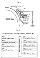
- FIG. 9 is a block diagram for explaining a control system configuration.
- An arithmetic control section B10 contained in a liquid-development electrophotographic apparatus B01 fetches a required program segment from a control program stored in a control program section B18 and executes a predetermined control procedure.
- a printing drive section B11 includes a drive system for driving the intermediate transfer member 1 illustrated in FIG. 1 and a press-contact drive system for driving the backup roller 9 illustrated in FIG. 1.
- An image formation section B12 includes drive systems for driving the corresponding developing units 4, 5, 6, and 7 illustrated in FIG. 1, and a drive system for driving the carrier-removing unit 8 illustrated in FIG. 1.
- a cleaning drive section B13 includes components of the cleaning unit 2, and mechanisms provided around the periphery of the components.
- a memory section B14 stores a cleaning condition table, which will be described later.
- An error detection section B15 reports to the arithmetic control section B10 signals obtained from various error detection sensors disposed in the liquid-development electrophotographic apparatus B01. On the basis of the type of an error detection signal reported from the error detection section B15, the arithmetic control section B10 sets an operation pattern of a cleaning mode.
- Step S01 an operator selects a cleaning mode as an operation mode of the liquid-development electrophotographic apparatus B01; and the arithmetic control section B10 fetches a program segment related to the cleaning mode from the control program section B18 and specifies a predetermined control procedure.
- the liquid-development electrophotographic apparatus B01 when the number of image formation operations performed by the liquid-development electrophotographic apparatus B01 reaches a predetermined value, or when the liquid-development electrophotographic apparatus B01 detects an error which requires cleaning for recovery, the liquid-development electrophotographic apparatus B01 indicates necessity to perform cleaning, thereby reporting to the operator.
- Step S02 the arithmetic control section B10 examines the contents of error data (data indicative of, for example, which sensor has detected an error) reported from the error detection section B15.
- Step S03 the arithmetic control section B10 references the cleaning condition table stored in the memory section B14. Then, proceeding to Step S04, the arithmetic control section B10 sets cleaning conditions corresponding to the combination of error data. Specifically, for example, when the error detection section B15 detects a paper jam, the intermediate transfer member 1 is considered to carry a large quantity of toner as residual toner because of nonexecution of transfer. Thus, the arithmetic control section B10 lowers the rotational speed of the intermediate transfer member 1 and raises the rotational speed of the application friction roller 21 so as to increase the quantity of application of a cleaning liquid. Notably, the correspondence between the status of an error and a remedial action is determined beforehand and written in the cleaning condition table.
- the liquid-development electrophotographic apparatus B01 can set a corresponding table which defines the correspondence between the contents of the obtained error data and cleaning conditions, to thereby construct a foundation for automatically setting cleaning conditions by classifying the error data.
- Step S05 the development control section B16b retreats the image formation section B12. Specifically, this retreat operation causes the developing units 4, 5, 6, and 7 and the carrier-removing unit 8 illustrated in FIG. 1 to separate from the intermediate transfer member 1.
- Step S06 the printing control section B16b retreats the printing drive section B11. Specifically, this retreat operation causes the backup roller 9 illustrated in FIG. 1 to separate from the intermediate transfer member 1.
- Step S07 the arithmetic control section B10 starts a cleaning operation. Specifically, in this cleaning operation, the intermediate transfer member 1 rotates for a predetermined period of time while remaining in contact with the cleaning unit 2.
- the cleaning unit 2 performs a cleaning operation at a rotational speed which is determined on the basis of the previously set cleaning conditions. For example, in the case where a cleaning mode for recovery is set upon detection of an error indicating that passage of a printing medium is not detected, in order to cope with a large quantity of untransferred toner, cleaning conditions are set in such a manner as to lower the rotational speed of the intermediate transfer member and to raise the rotational speed of the collection roller.
- cleaning conditions are set in such a manner as to lower the rotational speed of the intermediate transfer member and to increase the rotational speed of the application roller.
- Step S08 the arithmetic control section B10 ends a cleaning operation. Then, proceeding to Step S09, the arithmetic control section B10 cancels the retreat operation of the image formation section B12 and the retreat operation of the printing drive section B11, performed for the cleaning mode. Subsequently, the arithmetic control section B10 proceeds to Step S10 and stands by in preparation for the subsequent image formation mode.
- a cleaning liquid is applied to an intermediate transfer member which has transferred an image to a printing medium.
- the cleaning liquid infiltrates into residual developer remaining on the intermediate transfer member, thereby weakening cohesion/firm adhesion of the residual developer remaining on the intermediate transfer member. Furthermore, the cleaning liquid again liquefies the residual developer cohering/firmly adhering to the intermediate transfer member. Also, since a bias voltage is applied to the intermediate transfer member in such a direction as to cause exfoliation of developer, residual developer remaining on the intermediate transfer member is exfoliated from the intermediate transfer member. The residual developer exfoliated from the intermediate transfer member is collected together with the cleaning liquid. Thus, residual developer which coheres/firmly adheres to the intermediate transfer member in a stubborn manner can be effectively and stably cleaned off.
Landscapes
- Physics & Mathematics (AREA)
- General Physics & Mathematics (AREA)
- Electrostatic Charge, Transfer And Separation In Electrography (AREA)
- Wet Developing In Electrophotography (AREA)
Abstract
After passing a position of transfer to a printing
medium 10, a portion of an intermediate transfer member 1 on
which an image is previously formed reaches the position of a
cleaning unit 2. The cleaning unit 2 removes residual toner,
whereby the intermediate transfer member 1 prepares for a
next cycle of formation of images in the corresponding colors
by means of the developing units 4, 5, 6, and 7. The
cleaning unit 2 includes an application friction roller 21
and a bias roller 24. The application friction roller 21 has
a function to weaken cohesion/firm adhesion of residual toner
through application of a cleaning liquid to the intermediate
transfer member 1 and a function to exfoliate and disperse
the residual toner in the cleaning liquid through imposition
of a shear force on the residual toner. The bias roller 24
includes a bias voltage generation mechanism 24a for applying
a bias voltage between the bias roller 24 and the
intermediate transfer member 1. Application of a bias
voltage weakens the force of adhesion of residual toner
firmly adhering to the surface of the intermediate transfer
member 1, whereby the residual toner exfoliates from the
intermediate transfer member 1 and disperses in the cleaning
liquid. The bias roller 24 is further adapted to collect the
thus-exfoliated, dispersed residual toner.
Description
The present invention relates to a cleaning method and
a cleaning apparatus for a liquid-development
electrophotographic apparatus which uses a liquid developer
(liquid toner), and particularly to a cleaning method and a
cleaning apparatus for a liquid-development
electrophotographic apparatus which are capable of
effectively and stably cleaning off residual developer
(residual toner) that coheres and firmly adheres to an
intermediate transfer member.
FIG. 11 shows a conceptual configuration of a
conventional liquid-development electrophotographic apparatus.
As shown in FIG. 11, the conventional liquid-development
electrophotographic apparatus has an intermediate transfer
member 51 formed of a roller which is rotated at a
predetermined speed; and a backup roller 59 which is in press
contact with the intermediate transfer member 51 and is
rotated such that a contact portion of the backup roller 59
and a contact portion of the intermediate transfer member 51
move in the same direction. An image formed of liquid toner
on the surface of the intermediate transfer member 51 is
transferred to a printing medium 60, which is moved while
being nipped between the intermediate transfer member 51 and
the backup roller 59.
An image to be transferred to the printing medium 60
from the intermediate transfer member 51 consists of a yellow
element image, which is in yellow toner and transfer-supplied
from a developing unit 54; a red element image, which is in
red toner and transfer-supplied from a developing unit 55; a
blue element image, which is in blue toner and transfer-supplied
from a developing unit 56; and a black element image,
which is in black toner and transfer-supplied from a
developing unit 57.
The developing unit 54, which transfer-supplies a
yellow element image to the intermediate transfer member 51,
includes a toner supply pot 54d for storing a yellow liquid
toner; a pattern roller 54c for taking out the liquid toner
from the toner supply pot 54d; a developing roller 54b for
leveling the liquid toner supplied from the pattern roller
54c so as to form a toner layer of uniform thickness; and a
photoconductor drum 54a for forming a yellow element image by
use of the toner layer transfer-supplied from the developing
roller 54b.
The yellow liquid toner stored in the toner supply pot
54d is supplied in a state of including a carrier, which is a
nonvolatile liquid. Thus, the carrier, which is a
nonvolatile liquid, adheres to the surface of the
intermediate transfer member 51 on which a yellow element
image is formed.
Subsequently to being transfer-supplied with a yellow
element image, the intermediate transfer member 51 is
similarly transfer-supplied with a red element image from the
developing unit 55. Then, the intermediate transfer member
51 is sequentially transfer-supplied with a blue element
image from the developing unit 56, and a black element image
from the developing unit 57, thereby forming a color image as
a whole.
Each of the developing unit 55, the developing unit 56,
and the developing unit 57 assumes a configuration similar to
the aforementioned configuration of the yellow-related
developing unit 54. Accordingly, a color image is formed on
the surface of the intermediate transfer member 51 by means
of yellow liquid toner, red liquid toner, blue liquid toner,
and black liquid toner; and a carrier contained in the color
toners adheres to the surface of the intermediate transfer
member 51.
Although unillustrated in FIG. 11, the surface of the
photoconductor drum associated with each of the colors is
equipped with, for example, an image formation mechanism for
electrostatically forming a latent image, and an accessory
mechanism therefor; a mechanism for eliminating static
electricity from the surface of the photoconductor drum after
transfer-supply of the corresponding element image to the
intermediate transfer member 51; and a mechanism for removing
residual toner.
When an image formed on the surface of the intermediate
transfer member 51 passes a position of contact with a
carrier-removing unit 58, the carrier is removed from the
image. Then, the image―which is formed of the color
toners―is transferred to the printing medium 60, which moves
while being nipped under pressure between the backup roller
59 and the intermediate transfer member 51. The image
transferred to the printing medium 60 is fixed in a fixing
unit (not shown).
After passing a position of transfer to the printing
medium 60, a portion of the intermediate transfer member 51
on which an image is previously formed reaches the position
of a cleaning unit 52. The cleaning unit 52 removes residues
of toner (hereinafter, called "residual toner" or "residual
developer"), whereby the intermediate transfer member 51
prepares for a next cycle of forming images in the
corresponding colors by means of the developing units 54, 55,
56, and 57.
The conventional cleaning unit 52 shown in FIG. 11 will
be described in detail with reference to FIG. 12. The
cleaning unit 52 includes a blade 52a which is in press
contact with the intermediate transfer member 51, and a
residual-toner pot 52b. The blade 52a scrapes off residual
toner of firm adhesion from the surface of the intermediate
transfer member 51, thereby collecting the residual toner in
the residual-toner pot 52b.
FIG. 13 shows another conventional cleaning unit. As
shown in FIG. 13, the cleaning unit 52 includes an
electrically conductive elastic-body roller 62a in press
contact with the intermediate transfer member 51, and an
elastic cleaning blade 62b disposed downstream of the roller
62a. The electrically conductive elastic-body roller 62a is
grounded, or a bias voltage opposite in polarity to an
electrostatic latent image is applied to the electrically
conductive elastic-body roller 62a. Specifically, a bias
voltage polarized in such a direction as to cause exfoliation
of residual toner is applied between the electrically
conductive elastic-body roller 62a and the intermediate
transfer member 51 to thereby exfoliate from the intermediate
transfer member 51 residual toner-which coheres/firmly
adheres to the intermediate transfer member 51. The elastic
cleaning blade 62b is adapted to remove, from the
intermediate transfer member 51, the residual toner which is
exfoliated from the intermediate transfer member 51 by means
of the elastic-body roller 62a.
Usually, a 4-color image formed on the intermediate
transfer member 51 is not entirely transferred to a printing
medium. Residual developer (residual toner) which remains on
the intermediate transfer member 51 without being transferred
to the printing medium is removed in a period of time ranging
from the end of a transfer process in which the intermediate
transfer member 51 makes one rotation to thereby transfer a
toner image to the printing medium, to the start of a
subsequent process in which a toner image is transferred from
a photoconductor drum to the intermediate transfer member 51.
In other words, the residual developer is removed by means of
the cleaning unit located upstream of the developing unit 54
and downstream of the backup roller 59, which is disposed in
opposition to the intermediate transfer member 51 provided
for transferring a toner image to the printing medium.
However, in an ordinary image formation operation,
residual toner subjected to a cleaning operation of the
cleaning unit is a residue of toner left in transfer of a
toner image to the printing medium 60. Thus, the quantity of
adhering residual toner is small, but the residual toner
adheres firmly to the intermediate transfer member 51. The
above-described conventional configuration fails to
completely remove such a firmly adhering residual toner.
Furthermore, in the course of repetition of an image
formation operation, residual toner which the cleaning unit
52 has failed to collect gradually accumulates and begins to
mix in an image formed on the surface of the intermediate
transfer member 51, thereby affecting the quality of an image
which the intermediate transfer member 51 forms. Meanwhile,
for example, when a printing medium is not supplied because
of a certain error, most of an image formed on the surface of
the intermediate transfer member 51 is subjected to a
cleaning operation as residual toner. In such a case, the
cleaning operation must handle a large amount of residual
toner. Thus, the operation mode of the liquid-development
electrophotographic apparatus must be changed over to a
cleaning mode for removing residual toner.
Thus, when the number of image formation operations of
the liquid-development electrophotographic apparatus reaches
a predetermined value or when the liquid-development
electrophotographic apparatus suffers an error which requires
a recovery operation accompanied by cleaning, an operator
changes over the operation mode of the apparatus to a
cleaning mode and causes the apparatus to perform the
cleaning operation a predetermined number of times, thereby
preventing deterioration in the quality of an image formed by
means of the intermediate transfer member 51.
Such a conventional cleaning-mode operation to be
performed by a liquid-development electrophotographic
apparatus will be described with reference to FIGS. 14 and 15.
A configuration required for description of a control
procedure will be described with reference to the block
diagram of FIG. 14. An arithmetic control section B50
contained in a liquid-development electrophotographic
apparatus B05 fetches a required program segment from a
control program stored in a control program section B58 and
executes a predetermined control procedure.
A printing drive section B51 includes a drive system
for driving the intermediate transfer member 51, and a press-contact
drive system for driving the backup roller 59. An
image formation section B52 includes drive systems for
driving the corresponding developing units 54, 55, 56, and 57,
and a drive system for driving the carrier-removing unit 58.
An error detection section B55 reports to the
arithmetic control section B50 signals obtained from various
error detection sensors disposed in the liquid-development
electrophotographic apparatus B05.
A printing control section B56a specifies an operation
which the printing drive section B51 is to perform, timing of
performing the operation, and the like; and a development
control section B56b specifies an operation which the image
formation section B52 is to perform, timing of performing the
operation, and the like.
Control procedure will be described with reference to
the flowchart of FIG. 15. For example, when the number of
image formation operations performed by the liquid-development
electrophotographic apparatus B05 reaches a
predetermined value, or when the liquid-development
electrophotographic apparatus B05 suffers an error which
requires a recovery operation accompanied by cleaning, the
liquid-development electrophotographic apparatus B05
indicates necessity to perform cleaning. As a matter of
course, the degree of contamination of the intermediate
transfer member depends on the contents of an image which the
liquid-development electrophotographic apparatus B05 forms.
Thus, an operator must monitor the conditions of printing
media ejected from the liquid-development electrophotographic
apparatus B05 and set an appropriate timing of performing
cleaning.
In Step S51, the operator selects a cleaning mode as an
operation mode of the liquid-development electrophotographic
apparatus B05. This causes the arithmetic control section
B50 to fetch a program segment associated with the cleaning
mode from the control program section B58 and to execute the
program segment.
In Step S52, the development control section B56b
retreats the image formation section B52. Specifically, this
retreat operation causes the developing units 54, 55, 56, and
57 and the carrier-removing unit 58 to separate from the
intermediate transfer member 51.
In Step S53, the printing control section B56a retreats
the printing drive section B51. Specifically, this retreat
operation causes the backup roller 59 to separate from the
intermediate transfer member 51.
In Step S54, the arithmetic control section B50 starts
a cleaning operation. Specifically, in this cleaning
operation, the intermediate transfer member 51 rotates for a
predetermined period of time while remaining in contact with
the cleaning unit 52.
In Step S55, the arithmetic control section B50 ends
the cleaning operation. Then, proceeding to Step S56, the
arithmetic control section B50 cancels the retreat operation
of the image formation section B52 and the retreat operation
of the printing drive section B51 performed for the cleaning
mode. Then, proceeding to Step S57, the arithmetic control
section B50 stands by in preparation for the subsequent image
formation mode.
As described above, since the degree of contamination
of the intermediate transfer member depends on the contents
of an image which the liquid-development electrophotographic
apparatus forms, an operator must monitor the conditions of
printing media ejected from the liquid-development
electrophotographic apparatus and set appropriate cleaning
conditions.
Prior to the step of transferring an image from an
intermediate transfer member to a printing medium, in order
to prevent deterioration in printing quality stemming from
wetting of the printing medium or a like cause, a carrier
liquid, which is a liquid component of a liquid developer,
must be appropriately removed from the liquid developer
(toner image) transferred to the intermediate transfer member.
In so doing, toner solids (resin containing pigment or dye)
contained in the liquid developer cohere/firmly adhere to the
intermediate transfer member.
Residual developer which remains on the intermediate
transfer member without being transferred to the printing
medium coheres/firmly adheres to the intermediate transfer
member in a stubborn manner. Specifically, at the time of
transfer to the printing medium, the liquid developer is
heated to a temperature equal to or higher than the softening
point of toner solids (resin containing pigment or dye)
contained in the liquid developer, and is subjected to high
pressure. Accordingly, residual developer which remains on
the intermediate transfer member without being transferred to
the printing medium coheres/firmly adheres to the
intermediate transfer member in a stubborn manner.
The present invention has been accomplished in view of
the foregoing, and an object of the invention is to
effectively and stably clean off residual developer which
coheres/firmly adheres to the intermediate transfer member in
a stubborn manner, when a liquid-development
electrophotographic apparatus using a liquid developer
performs cleaning.
Since difficulty is encountered in completely
collecting residual toner which stubbornly and firmly adheres
to the intermediate transfer member, uncollected residual
toner accumulates, and thus an unnecessary image component
tends to appear on a formed image. Therefore, repeated image
formation involves deterioration in image quality.
Thus, another object of the present invention is to
construct a foundation for optimally setting cleaning
conditions for different degrees of contamination of the
intermediate transfer member through performance of a
cleaning operation suited for the details of an error arising
in the liquid-development electrophotographic apparatus.
According to the present invention, a cleaning liquid
is applied to the intermediate transfer member which has
transferred an image to the printing medium, to thereby
weaken cohesion/firm adhesion of residual developer to the
intermediate transfer member and again liquefy the residual
developer cohering/firmly adhering to the intermediate
transfer member. Furthermore, in order to exfoliate residual
developer, which coheres/firmly adheres to the intermediate
transfer member, from the intermediate transfer member, a
bias voltage is applied to the intermediate transfer member.
The residual developer exfoliated from the intermediate
transfer member is collected together with the cleaning
liquid.
A cleaning method of the present invention for a
liquid-development electrophotographic apparatus using a
liquid developer comprises a cleaning-liquid application step
of applying a cleaning liquid to the intermediate transfer
member which has transferred an image to the printing medium;
a bias voltage application step of applying, to the
intermediate transfer member, a bias voltage opposite in
polarity to charged toner particles of the residual developer
(a bias voltage polarized in such a direction as to cause
exfoliation of the developer); and a collection step of
removing, from the intermediate transfer member, the cleaning
liquid which has been applied in the cleaning-liquid
application step, and the residual developer which remains on
the intermediate transfer member without transfer of an image
to the printing medium, and collecting the removed cleaning
liquid and residual developer.
A cleaning apparatus of the present invention for a
liquid-development electrophotographic apparatus using a
liquid developer is configured such that a cleaning unit for
removing residual developer from the intermediate transfer
member is disposed upstream of a developing unit and
downstream of a backup roller, which is disposed in
opposition to the intermediate transfer member so as to
transfer a toner image to a printing medium. This cleaning
unit comprises a cleaning-liquid application mechanism for
applying a cleaning liquid to the intermediate transfer
member which has transferred an image to the printing medium;
a bias voltage application mechanism for applying, to the
intermediate transfer member, a bias voltage opposite in
polarity to charged toner particles of the developer (a bias
voltage polarized in such a direction as to cause exfoliation
of the developer); and a collection mechanism for removing,
from the intermediate transfer member, the cleaning liquid
which has been applied by means of the cleaning-liquid
application mechanism, and the residual developer which
remains on the intermediate transfer member without transfer
of an image to the printing medium, and collecting the
removed cleaning liquid and residual developer.
A cleaning method and apparatus for a liquid-development
electrophotographic apparatus according to the
present invention will next be described, by way of example.
FIG. 1 is a conceptual view showing the configuration of a
liquid-development electrophotographic apparatus including a
first example of a cleaning apparatus to which the present
invention is applied.
As shown in FIG. 1, the liquid-development
electrophotographic apparatus includes an intermediate
transfer member 1 which is rotated at a predetermined speed
and assumes a roller shape; and a backup roller 9 which is in
press contact with the intermediate transfer member 1 and is
rotated such that a contact portion of the backup roller 9
and a contact portion of the intermediate transfer member 1
move in the same direction. An image formed of liquid toner
on the surface of the intermediate transfer member 1 is
transferred to a printing medium 10, which is moved while
being nipped between the intermediate transfer member 1 and
the backup roller 9.
An image to be transferred to the printing medium 10
from the intermediate transfer member 1 consists of a yellow
element image, which is in yellow toner and transfer-supplied
from a developing unit 4; a red element image, which is in
red toner and transfer-supplied from a developing unit 5; a
blue element image, which is in blue toner and transfer-supplied
from a developing unit 6; and a black element image,
which is in black toner and transfer-supplied from a
developing unit 7.
The developing unit 4, which transfer-supplies a yellow
element image to the intermediate transfer member 1, includes
a toner supply pot 4d for storing yellow liquid toner; a
pattern roller 4c for taking out the liquid toner from the
toner supply pot 4d; a developing roller 4b for leveling the
liquid toner supplied from the pattern roller 4c so as to
form a toner layer of uniform thickness; and a photoconductor
drum 4a for forming a yellow element image by use of the
toner layer transfer-supplied from the developing roller 4b.
Although unillustrated in FIG. 1, the surface of the
photoconductor drum 4a is equipped with, for example, an
image formation mechanism for electrostatically forming a
latent image, along with an accessory mechanism therefor; a
mechanism for eliminating static electricity from the surface
of the photoconductor drum 4a after transfer-supply of a
yellow element image to the intermediate transfer member 1;
and a mechanism for removing residual toner.
The yellow liquid toner stored in the toner supply pot
4d is supplied in a state including a carrier, which is a
nonvolatile liquid. Thus, the carrier, which is a
nonvolatile liquid, adheres to the surface of the
intermediate transfer member 1 on which a yellow element
image is formed.
Subsequently to being transfer-supplied with a yellow
element image, the intermediate transfer member 1 is
transfer-supplied with a red element image from the
developing unit 5. Then, the intermediate transfer member 1
is sequentially transfer-supplied with a blue element image
from the developing unit 6, and a black element image from
the developing unit 7, thereby forming a color image as a
whole.
Each of the developing units 5, 6, and 7 assumes a
configuration similar to the aforementioned configuration of
the developing unit 4. Accordingly, an image is formed on
the surface of the intermediate transfer member 1 by means of
yellow liquid toner, red liquid toner, blue liquid toner, and
black liquid toner; and the carrier contained in the color
toners adheres to the surface of the intermediate transfer
member 1.
When an image formed on the surface of the intermediate
transfer member 1 passes a position of contact with a
carrier-removing unit 8, the carrier is separated and removed
from the image. Then, the image, formed of the color toners,
is transferred to the printing medium 10, which moves while
being nipped under pressure between the backup roller 9 and
the intermediate transfer member 1. Notably, the carrier-removing
unit 8 is adapted to remove a carrier oil contained
in an image which is formed on the intermediate transfer
member 1 by means of liquid toners. The image transferred to
the printing medium 10 is fixed in a fixing unit (not shown).
After passing a position of transfer to the printing
medium 10, a portion of the intermediate transfer member 1 on
which an image is previously formed reaches the position of a
cleaning unit 2. The cleaning unit 2 removes residual toner,
whereby the intermediate transfer member 1 prepares for a
next cycle of formation of images in the corresponding colors
by means of the developing units 4, 5, 6, and 7. The above-described
liquid-development electrophotographic apparatus
can be configured to have a structure similar to a
conventionally known structure, or the structure described
previously with reference to FIG. 11, except for the
structure of the cleaning unit 2.
Next, the cleaning unit, which is the feature of the
present invention, will next be described in detail with
reference to FIGS. 2 to 4, which show a first example of the
cleaning unit. FIG. 2 is a view showing the details of the
cleaning unit 2 shown in FIG. 1.
Residual developer which remains on the intermediate
transfer member 1 without being transferred to a printing
medium must be removed in a period to time ranging from the
end of a transfer process in which the intermediate transfer
member 1 makes one rotation to thereby transfer a toner image
to the printing medium, to the start of a subsequent process
in which a toner image is transferred from the photoconductor
drum of the developing unit 4 to the intermediate transfer
member 1. Thus, the cleaning unit 2 is located upstream of
the developing unit 4 and downstream of the backup roller 9,
which is disposed in opposition to the intermediate transfer
member 1 provided for transferring a toner image to the
printing medium.
As shown in FIG. 2, the cleaning unit 2 includes an
application friction roller 21 and a bias roller 24, each of
which presses the intermediate transfer member 1 at a
predetermined pressure and is rotated in such a manner as to
move at variable speed in an opposite direction with respect
to movement of the intermediate transfer member 1. Notably,
herein, the expression "to move in opposite directions" means
that mutually facing portions move in opposite directions.
According to this definition, for example, when two rollers
in contact with each other rotate in the same direction (for
example, rotate clockwise), contact portions of the rollers
move in mutually opposite directions.
Although the details will be described later, the
application friction roller 21 also has a function to apply a
shear force to residual toner so as to exfoliate and disperse
the residual toner in a cleaning liquid. The bias roller 24
includes a bias voltage generation mechanism 24a for applying
a bias voltage between the bias roller 24 and the
intermediate transfer member 1. Thus, the bias roller 24 has
a function to weaken the force of adhesion of residual toner
firmly adhering to the surface of the intermediate transfer
member 1 through application of a bias voltage to the
intermediate transfer member 1; to exfoliate the residual
toner of weakened adhesion from the intermediate transfer
member 1; and to disperse the exfoliated residual toner in a
cleaning liquid. A collection blade 25 has the function to
collect the thus-exfoliated, dispersed residual toner.
The application friction roller 21, intermediate
rollers 22a and 22b, and a first pot 23 constitute an
application mechanism for applying a cleaning liquid to the
intermediate transfer member 1. The cleaning liquid is a
substance substantially equal to a carrier liquid contained
in a liquid toner used to form an image on the intermediate
transfer member 1. For example, a nonvolatile liquid such as
silicone oil is used as the cleaning liquid.
A cleaning liquid stored in the first pot 23 is taken
out in such a manner as to adhere to the surface of the first
intermediate roller 22b, which is rotated while being
immersed in the stored cleaning liquid. Next, the cleaning
liquid is transferred to the surface of the application
friction roller 21 via the second intermediate roller 22a.
The cleaning liquid which is transferred and adheres to the
surface of the application friction roller 21 is transferred
to the surface of the intermediate transfer member 1. As
described previously, the cleaning liquid transferred to the
surface of the intermediate transfer member 1 is a substance
substantially equal to a carrier liquid. Thus, the cleaning
liquid infiltrates into residual toner that firmly adheres to
the surface of the intermediate transfer member 1, thereby
weakening the force of adhesion of the residual toner.
Furthermore, while the surface of the application
friction roller 21 which holds the cleaning liquid is pressed
at a predetermined pressure against the intermediate transfer
member 1, the application friction roller 21 and the
intermediate transfer member 1 move in mutually opposite
directions. Thus, residual toner firmly adhering to the
surface of the intermediate transfer member 1 is subjected to
a shear force which is induced by a frictional force of the
application friction roller 21 and acts along the surface of
the intermediate transfer member 1. The shear force induced
by the frictional force of the application friction roller 21
and imposed on residual toner functions as a force of
canceling the force of adhesion of the residual toner firmly
adhering to the surface of the intermediate transfer member 1
to thereby exfoliate the residual toner from the intermediate
transfer member 1. The residual toner exfoliated, by this
shear force, from the surface of the intermediate transfer
member 1 is dispersed in the cleaning liquid supplied from
the application friction roller 21. This tells that the
application friction roller 21 has a function to apply a
cleaning liquid and a function to exfoliate residual toner
through friction against the residual toner and disperse the
residual toner in the cleaning liquid.
The application friction roller 21, the intermediate
roller 22a, and the intermediate roller 22b can be configured
in such a manner as to be rotated at variable speed. For
example, when the rotational speed of the application
friction roller 21 in contact with the surface of the
intermediate transfer member 1 is increased, the surface area
of the application friction roller 21 in sliding contact
with a unit area of the surface of the intermediate transfer
member 1 increases, and thus the quantity of friction and the
quantity of cleaning liquid transferring from the surface of
the application friction roller 21 to the surface of the
intermediate transfer member 1 increase. In other words, the
capability to exfoliate and disperse residual toner can be
controlled through control of the rotational speed of the
application friction roller 21 and the intermediate rollers
22a and 22b.
An outlet portion (distal end) of a drain mechanism 27
is located at height D above the bottom surface of the first
pot 23. A supply port portion (distal end) of a reflux
mechanism 28, which will be described later, is located above
the liquid surface of the first pot 23. The maximum drain
rate of the drain mechanism 27 is set higher than the maximum
supply rate of the reflux mechanism 28. Through employment
of this setting, the level of a cleaning liquid stored in the
first pot 23 does not exceed a predetermined height (i.e.,
height D above the bottom surface) and does not drop below
this predetermined height D.
Next, the details of the structure of the application
friction roller 21 will be described with reference to FIG. 3.
A surface layer 21a is formed on the surface of the
application friction roller 21. The surface layer 21a is
formed of a resin-material or rubber-material foam or a
member (nonwoven fabric, felt, or the like) made of fine
fiber. When the application friction roller 21 transfers a
cleaning liquid-which is transferred to the application
friction roller 21 from the intermediate roller 22a―to the
intermediate transfer member 1, the application friction
roller 21 holds the cleaning liquid in pits of the surface
layer 21a formed of a foam or fine fiber and stably applies
the cleaning liquid; and projections of the surface layer 21a
impose a shear force on residual toner firmly adhering to the
intermediate transfer member 1, by means of a frictional
force generated through continuous sliding of the projections.
Again with reference to FIG. 2, the bias roller 24 and
its peripheral structures will be described in terms of
configuration, action, and effect. The bias roller 24, the
blade 25, and a second pot 26 constitute a collection
mechanism for collecting, from the surface of the
intermediate transfer member 1, a cleaning liquid which
contains residual toner in a dispersed condition.
The surface of the bias roller 24 is in press contact
with the surface of the intermediate transfer member 1 and
moves in an opposite direction with respect to the surface of
the intermediate transfer member 1; the bias roller 24
adsorbs residual toner through application of a bias voltage;
and the bias roller 24 wipes off the cleaning liquid applied
to the surface of the intermediate transfer member 1 to
thereby collect the cleaning liquid. In so doing, residual
toner dispersed in the cleaning liquid, together with the
cleaning liquid, transfers from the surface of the
intermediate transfer member 1 to the surface of the bias
roller 24.
The residual toner and the cleaning liquid transferred
to the surface of the bias roller 24 is scraped together by
means of the blade 25 in contact with the bias roller 24 and
is collected in the second pot 26. Thus, the residual toner
which, previously, firmly adheres to the intermediate
transfer member 1 is collected, together with the cleaning
liquid, in the second pot 26 via the bias roller 24.
The bias roller 24 includes the bias voltage generation
mechanism 24a, which applies a bias voltage between the bias
roller 24 and the intermediate transfer member 1 located in
opposition to the bias roller 24. This bias voltage weakens
the force of adhesion of residual toner firmly adhering to
the surface of the intermediate transfer member 1. As a
result, the residual toner exfoliates from the intermediate
transfer member 1; disperses in the cleaning liquid; and is
adsorbed on the bias roller 24. This tells that the bias
roller 24 has a function to collect residual toner and a
function to exfoliate and disperse the residual toner by use
of the bias voltage generation mechanism 24a.
The reflux mechanism 28 is connected to the bottom of
the second pot 26, which collects the cleaning liquid
containing the residual toner dispersed therein. The reflux
mechanism 28 transfers the cleaning liquid from the second
pot 26 to the first pot 23 by means of a reflux pump 28a.
The reflux mechanism 28 includes a cleaning-liquid
regeneration mechanism 28c, which removes residual toner
dispersing in the cleaning liquid so as to prevent
deterioration of the cleaning liquid for reuse. Notably,
when the cleaning liquid from the second pot 26 is rendered
unavailable, the reflux pump 28a changes over the cleaning-liquid
supply source to a replenishment mechanism 28b and
transfers a new cleaning liquid to the first pot 23 from a
replenishment pot (not shown) connected to the replenishment
mechanism 28b.
The details of the structure of the bias roller 24
shown in FIG. 2 will be described with reference to FIG. 4.
A surface resin layer 24b is formed on the bias roller 24.
The surface roughness of the surface resin layer 24b is set
such that a 10-point average roughness (Rz) is 3 µm or less.
Through retainment of this surface roughness, appropriate
smoothness is ensured to the surface of the bias roller 24,
whereby the blade 25 in contact with the bias roller 24 can
efficiently and stably scrape off a cleaning liquid.
An electrical characteristic of the surface resin layer
24b formed on the surface of the bias roller 24 is set such
that volume resistance substantially falls within a range of
10 kΩ to 10 GΩ. Through retainment of this volume
resistance, the bias voltage generation mechanism 24a
contained in the bias roller 24 can efficiently apply a bias
voltage.
Notably, the above-described cleaning unit employs a
roller structure for the application friction roller 21 and
the bias roller 24. However, in place of a roller structure,
a belt structure may be employed for the application friction
roller 21 and/or the bias roller 24. Herein, the term
"rotary member" means a structure in which continuously
repetitive portions of a mobile member circulate and
sequentially perform a predetermined operation, such as a
structure implemented by the surface of, for example, such a
roller or belt.
FIG. 5 is a view showing a second example of a cleaning
apparatus to which the present invention is applied. In FIG.
5, as in the case of the first example, the cleaning unit 2
is located upstream of the developing unit 4 and downstream
of the backup roller 9, which is disposed in opposition to
the intermediate transfer member 1 provided for transferring
a toner image to the printing medium 10.
The cleaning unit 2 includes a cleaning-liquid
application roller 11, a bias voltage application mechanism
12, and a collection blade 13. The cleaning unit 2 is
configured in such a manner as to be able to come into
contact with and retreat from the intermediate transfer
member 1 by means of a contact/retreat mechanism.
The cleaning-liquid application roller 11 applies a
cleaning liquid to the intermediate transfer member 1 which
has transferred an image to the printing medium 10. This
cleaning-liquid application roller 11 is appropriately
supplied with a cleaning liquid from a storage pot via an
intermediate roller. The cleaning liquid applied by the
cleaning-liquid application roller 11 is infiltrated into
residual developer remaining on the intermediate transfer
member 1 to thereby weaken cohesion/firm adhesion of residual
developer to the intermediate transfer member 1 and again
liquefies the residual developer cohering/firmly adhering to
the intermediate transfer member.
The bias voltage application mechanism 12 is adapted to
apply, to the intermediate transfer member 1, a bias voltage
opposite in polarity to charged toner particles of developer
(a bias voltage polarized in such a direction as to cause
exfoliation of developer). Notably, in the present
embodiment, charged toner particles assume the plus polarity.
The bias voltage application mechanism 12 applies, between
the application roller 11 and the intermediate transfer
member 1, a bias voltage polarized in such a direction as to
cause exfoliation of developer, thereby weakening the force
of cohesion/adhesion of residual developer and exfoliating
from the intermediate transfer member 1 the residual
developer remaining on the intermediate transfer member 1 or
the liquefied residual developer.
The collection blade 13 collects the cleaning liquid
which has been applied by means of the cleaning-liquid
application roller 11, and residual developer exfoliated from
the intermediate transfer member 1 or liquefied residual
developer. The collected cleaning liquid is drained as
appropriate.
According to the above-described configuration, the
liquid-development electrophotographic apparatus using a
liquid developer performs cleaning in the following manner.
The force of cohesion/adhesion of residual developer
remaining on the intermediate transfer member is weakened,
and the residual developer of weakened cohesion/adhesion is
exfoliated from the intermediate transfer member.
Alternatively, residual developer cohering/firmly adhering to
the intermediate transfer member is again liquefied. The
thus-treated residual developer, together with a cleaning
liquid, is collected. Accordingly, residual developer which
coheres/firmly adheres to the intermediate transfer member in
a stubborn manner can be effectively and stably cleaned off.
FIG. 6 is a view showing a third example of a cleaning
apparatus to which the present invention is applied. In FIG.
6, in order to apply a cleaning liquid to the intermediate
transfer member 1, an application blade 15 formed of a felt
material is provided at a position where it faces a portion
of the intermediate transfer member 1 which has passed the
position of image transfer to the printing medium. The
application blade 15 is supplied with a cleaning liquid
supplied to a supply pan 14. The cleaning liquid supplied to
the supply pan 14 is controlled as appropriate so as to
maintain a constant liquid level. Also, preferably, in order
to heat residual developer remaining on the intermediate
transfer member 1 to a temperature equal to or higher than
the softening point of resin contained in the developer, a
cleaning liquid heated to a predetermined temperature is
supplied to the supply pan 14 for application thereof.
An electrically conductive brush 16 is used at a
position located downstream of the application blade 15 on
the intermediate transfer member 1. The electrically
conductive brush 16 is formed of an electrical conductor and
adapted to apply, to the intermediate transfer member 1, a
bias voltage opposite in polarity to charged toner particles
of the developer (a bias voltage polarized in such a
direction as to cause exfoliation of developer).
Furthermore, the collection blade 13 for removing, from
the intermediate transfer member 1, the cleaning liquid which
has been applied by means of the application blade 15, and
residual developer which remains on the intermediate transfer
member 1 without being transferred to the printing medium, is
provided downstream of the electrically conductive brush 16
on the intermediate transfer member 1. The collection blade
13 is in elastic press contact with the intermediate transfer
member 1 and collects, in a collection pan 17, residual
developer exfoliated from the intermediate transfer member 1
and the cleaning liquid which has been applied by means of
the application blade 15.
FIG. 7 is a view showing a fourth example of a cleaning
apparatus to which the present invention is applied. In FIG.
7, an application roller 31 for applying a cleaning liquid
and rubbing residual toner remaining on the intermediate
transfer member 1 is provided at a position where it faces a
portion of the intermediate transfer member 1 which has
passed the position of image transfer to the printing medium.
The application roller 31 is rotated in such a direction that,
in a contact zone where the application roller 31 is in
contact with the intermediate transfer member 1, contact
surfaces move in opposite directions. A cleaning liquid
supplied to a supply pan 14 is supplied to the application
roller 31 via a cleaning-liquid supply roller 34. Notably,
the application roller 31 may be rotated in such a direction
that, in a contact zone where the application roller 31 is in
contact with the intermediate transfer member 1, contact
surfaces move in the same direction.
Preferably, in order to heat residual developer
remaining on the intermediate transfer member 1 to a
temperature equal to or higher than the softening point of
resin contained in the developer, the application roller 31
contains a heater 35 which is heated beforehand to a
predetermined temperature.
An electrically conductive brush 32 is used at a
position located downstream of the application roller 31 on
the intermediate transfer member 1. The electrically
conductive brush 32 assumes the form of a rotary member and
is formed of an electrical conductor and adapted to apply, to
the intermediate transfer member 1, a bias voltage opposite
in polarity to charged toner particles of the developer (a
bias voltage polarized in such a direction as to cause
exfoliation of developer). The electrically conductive brush
32, which is a rotary member, is rotated in such a direction
that, in a contact zone where the electrically conductive
brush 32 is in contact with the intermediate transfer member
1, contact surfaces move in opposite directions. Notably,
the electrically conductive brush 32 may be rotated in such a
direction that, in a contact zone where the electrically
conductive brush 32 is in contact with the intermediate
transfer member 1, contact surfaces move in the same
direction.
As in the case of the previously described
configuration shown in FIG. 6, there is provided the
collection blade 13 for removing, from the intermediate
transfer member 1, the cleaning liquid which has been applied
by means of the application roller 31, and residual developer
which remains on the intermediate transfer member 1 without
being transferred to the printing medium. The collection
blade 13 is in elastic press contact with the intermediate
transfer member 1 and collects, in the collection pan 17,
residual developer exfoliated from the intermediate transfer
member 1 and the cleaning liquid which has been applied by
means of the application roller 31.
FIG. 8 is a view showing a fifth example of a cleaning
apparatus to which the present invention is applied. In FIG.
8, an application roller 41 is provided at a position where
it faces a portion of the intermediate transfer member 1
which has passed the position of image transfer to the
printing medium. The application roller 41 is formed of an
electrical conductor and adapted to apply, to the
intermediate transfer member 1, a carrier liquid and a bias
voltage opposite in polarity to charged toner particles of
the developer (a bias voltage polarized in such a direction
as to cause exfoliation of developer). An electrically
conductive brush is provided on the surface of the
application roller 41. The application roller 41 including
the electrically conductive brush is rotated in such a
direction that, in a contact zone where the application
roller 41 is in contact with the intermediate transfer member
1, contact surfaces move in opposite directions. A cleaning
liquid supplied to the supply pan 14 is supplied to the
application roller 41 including the electrically conductive
brush, via the cleaning-liquid supply roller 34. Notably,
the application roller 41 may be rotated in such a direction
that, in a contact zone where the application roller 41 is in
contact with the intermediate transfer member 1, contact
surfaces move in the same direction.
Preferably, in order to heat residual developer
remaining on the intermediate transfer member 1 to a
temperature equal to or higher than the softening point of
resin contained in the developer, the supply pan 14 contains
the heater 35 for heating, to a predetermined temperature,
the cleaning liquid to be supplied to the application roller
41.
As in the case of the previously described
configuration shown in FIG. 6 or 7, there is provided the
collection blade 13 for removing, from the intermediate
transfer member 1, the cleaning liquid which has been applied
by means of the application roller 41, and residual developer
which remains on the intermediate transfer member 1 without
being transferred to the printing medium. The collection
blade 13 is in elastic press contact with the intermediate
transfer member 1 and collects, in the collection pan 17,
residual developer exfoliated from the intermediate transfer
member 1 and the cleaning liquid which has been applied by
means of the application roller 41.
According to the illustrated configuration, the
application roller 41 applies a cleaning liquid to the
intermediate transfer member 1 which has transferred an image
to the printing medium, and applies a bias voltage to the
intermediate transfer member 1 in such a direction as to
cause exfoliation of developer, whereby the structure can be
simplified.
As shown in FIGS. 6 to 8, the cleaning liquid or the
cleaning-liquid application member is heated to a
predetermined temperature, whereby residual developer
remaining on the intermediate transfer member can be heated
to a temperature equal to or higher than the softening point
of resin contained in the developer, thereby weakening
adhesion of the residual developer and enhancing cleaning
performance. The heater may be contained in the cleaning-liquid
application roller or the cleaning-liquid supply pan.
Alternatively, the heater may be contained in the carrier-liquid
application blade 15 (FIG. 6). This allows easy
heating of a carrier liquid by means of a simple structure.
Also, in the case where the application roller is rotated
such that its surface moves in an opposite direction with
respect to movement of the intermediate transfer member,
friction in a contact zone between the intermediate transfer
member and the rotary member increases, thereby enhancing
cleaning performance.
Next will be described, with reference to FIGS. 9 and
10, control which the liquid-development electrophotographic
apparatus performs in carrying out a cleaning operation
corresponding to a cleaning mode. FIG. 9 is a block diagram
for explaining a control system configuration. An arithmetic
control section B10 contained in a liquid-development
electrophotographic apparatus B01 fetches a required program
segment from a control program stored in a control program
section B18 and executes a predetermined control procedure.
A printing drive section B11 includes a drive system
for driving the intermediate transfer member 1 illustrated in
FIG. 1 and a press-contact drive system for driving the
backup roller 9 illustrated in FIG. 1. An image formation
section B12 includes drive systems for driving the
corresponding developing units 4, 5, 6, and 7 illustrated in
FIG. 1, and a drive system for driving the carrier-removing
unit 8 illustrated in FIG. 1. A cleaning drive section B13
includes components of the cleaning unit 2, and mechanisms
provided around the periphery of the components. A memory
section B14 stores a cleaning condition table, which will be
described later.
An error detection section B15 reports to the
arithmetic control section B10 signals obtained from various
error detection sensors disposed in the liquid-development
electrophotographic apparatus B01. On the basis of the type
of an error detection signal reported from the error
detection section B15, the arithmetic control section B10
sets an operation pattern of a cleaning mode.
A printing control section B16a specifies an operation
which the printing drive section B11 is to perform, timing of
performing the operation, and the like; a development control
section B16b specifies an operation which the image formation
section B12 is to perform, timing of performing the operation,
and the like; and a cleaning control section B16c specifies
an operation which the cleaning drive section B13 is to
perform, timing of performing the operation, and the like.
Control procedure will be described with reference to
the flowchart of FIG. 10. In Step S01, an operator selects a
cleaning mode as an operation mode of the liquid-development
electrophotographic apparatus B01; and the arithmetic control
section B10 fetches a program segment related to the cleaning
mode from the control program section B18 and specifies a
predetermined control procedure.
For example, when the number of image formation
operations performed by the liquid-development
electrophotographic apparatus B01 reaches a predetermined
value, or when the liquid-development electrophotographic
apparatus B01 detects an error which requires cleaning for
recovery, the liquid-development electrophotographic
apparatus B01 indicates necessity to perform cleaning,
thereby reporting to the operator.
In Step S02, the arithmetic control section B10
examines the contents of error data (data indicative of, for
example, which sensor has detected an error) reported from
the error detection section B15.
In Step S03, the arithmetic control section B10
references the cleaning condition table stored in the memory
section B14. Then, proceeding to Step S04, the arithmetic
control section B10 sets cleaning conditions corresponding to
the combination of error data. Specifically, for example,
when the error detection section B15 detects a paper jam, the
intermediate transfer member 1 is considered to carry a large
quantity of toner as residual toner because of nonexecution
of transfer. Thus, the arithmetic control section B10 lowers
the rotational speed of the intermediate transfer member 1
and raises the rotational speed of the application friction
roller 21 so as to increase the quantity of application of a
cleaning liquid. Notably, the correspondence between the
status of an error and a remedial action is determined
beforehand and written in the cleaning condition table.
Through use of this principle, the liquid-development
electrophotographic apparatus B01 can set a corresponding
table which defines the correspondence between the contents
of the obtained error data and cleaning conditions, to
thereby construct a foundation for automatically setting
cleaning conditions by classifying the error data.
In Step S05, the development control section B16b
retreats the image formation section B12. Specifically, this
retreat operation causes the developing units 4, 5, 6, and 7
and the carrier-removing unit 8 illustrated in FIG. 1 to
separate from the intermediate transfer member 1.
In Step S06, the printing control section B16b retreats
the printing drive section B11. Specifically, this retreat
operation causes the backup roller 9 illustrated in FIG. 1 to
separate from the intermediate transfer member 1.
In Step S07, the arithmetic control section B10 starts
a cleaning operation. Specifically, in this cleaning
operation, the intermediate transfer member 1 rotates for a
predetermined period of time while remaining in contact with
the cleaning unit 2. The cleaning unit 2 performs a cleaning
operation at a rotational speed which is determined on the
basis of the previously set cleaning conditions. For example,
in the case where a cleaning mode for recovery is set upon
detection of an error indicating that passage of a printing
medium is not detected, in order to cope with a large
quantity of untransferred toner, cleaning conditions are set
in such a manner as to lower the rotational speed of the
intermediate transfer member and to raise the rotational
speed of the collection roller. Also, for example, in the
case where another cleaning mode is set based on data
indicating that the cumulative number of image formation
operations has reached a predetermined value, in order to
cope with stubbornly and firmly adhering residual toner,
cleaning conditions are set in such a manner as to lower the
rotational speed of the intermediate transfer member and to
increase the rotational speed of the application roller.
In Step S08, the arithmetic control section B10 ends a
cleaning operation. Then, proceeding to Step S09, the
arithmetic control section B10 cancels the retreat operation
of the image formation section B12 and the retreat operation
of the printing drive section B11, performed for the cleaning
mode. Subsequently, the arithmetic control section B10
proceeds to Step S10 and stands by in preparation for the
subsequent image formation mode.
In cleaning of a liquid-development electrophotographic
apparatus using a liquid developer, a cleaning liquid is
applied to an intermediate transfer member which has
transferred an image to a printing medium. The cleaning
liquid infiltrates into residual developer remaining on the
intermediate transfer member, thereby weakening cohesion/firm
adhesion of the residual developer remaining on the
intermediate transfer member. Furthermore, the cleaning
liquid again liquefies the residual developer cohering/firmly
adhering to the intermediate transfer member. Also, since a
bias voltage is applied to the intermediate transfer member
in such a direction as to cause exfoliation of developer,
residual developer remaining on the intermediate transfer
member is exfoliated from the intermediate transfer member.
The residual developer exfoliated from the intermediate
transfer member is collected together with the cleaning
liquid. Thus, residual developer which coheres/firmly
adheres to the intermediate transfer member in a stubborn
manner can be effectively and stably cleaned off.
Claims (13)
- A cleaning method for a liquid-development electrophotographic apparatus in which, after a toner image formed on a surface of an intermediate transfer member by use of a liquid developer is transferred to a printing medium, the liquid developer remaining on the intermediate transfer member is removed and collected, comprising:a cleaning-liquid application step of applying a cleaning liquid to the intermediate transfer member which has transferred an image to the printing medium;a bias voltage application step of applying, to the intermediate transfer member, a bias voltage opposite in polarity to charged toner particles of the residual developer; anda collection step of removing, from the intermediate transfer member, the cleaning liquid which has been applied in the cleaning-liquid application step, and the residual developer which remains on the intermediate transfer member without transfer of an image to the printing medium, and collecting the removed cleaning liquid and residual developer.
- A cleaning method for a liquid-development electrophotographic apparatus as described in claim 1, further comprising a step of rubbing the intermediate transfer member by use of a resin-material or rubber-material foam or a member formed of fine fiber when the cleaning liquid is applied.
- A cleaning method for a liquid-development electrophotographic apparatus as described in claim 1, wherein the cleaning-liquid application step includes a step of heating the residual developer on the intermediate transfer member to a temperature equal to or higher than a softening point of resin contained in the developer.
- A cleaning apparatus for a liquid-development electrophotographic apparatus in which, after a toner image formed on a surface of an intermediate transfer member by use of a liquid developer is transferred to a printing medium, the liquid developer remaining on the intermediate transfer member is removed and collected, comprising:a cleaning-liquid application device for applying a cleaning liquid to the intermediate transfer member which has transferred an image to the printing medium;a bias voltage application device for applying, to the intermediate transfer member, a bias voltage opposite in polarity to charged toner particles of the developer; anda collection device for removing, from the intermediate transfer member, the cleaning liquid which has been applied by means of the cleaning-liquid application device, and the residual developer which remains on the intermediate transfer member without transfer of an image to the printing medium, and collecting the removed cleaning liquid and residual developer.
- A cleaning apparatus for a liquid-development electrophotographic apparatus as described in claim 4, further comprising a friction device for rubbing the intermediate transfer member by use of a resin-material or rubber-material foam or a member formed of fine fiber when the cleaning liquid is applied.
- A cleaning apparatus for a liquid-development electrophotographic apparatus as described in claim 4, wherein the cleaning-liquid application device comprises a first blade for applying the cleaning liquid; the bias voltage application device comprises an electrically conductive brush formed of an electrical conductor and adapted to apply a bias voltage; and the collection device comprises a second blade for removing the applied cleaning liquid and the residual developer from the intermediate transfer member.
- A cleaning apparatus for a liquid-development electrophotographic apparatus as described in claim 4, wherein the cleaning-liquid application device comprises a rotary member for applying the cleaning liquid; the bias voltage application device comprises an electrically conductive brush formed of an electrical conductor and adapted to apply a bias voltage; and the collection device comprises a blade for removing the applied cleaning liquid and the residual developer from the intermediate transfer member.
- A cleaning apparatus for a liquid-development electrophotographic apparatus as described in claim 4, wherein the cleaning-liquid application device comprises a rotary member formed of an electrical conductor and adapted to apply the cleaning liquid; a bias voltage opposite in polarity to charged toner particles of the developer is applied between the rotary member and the intermediate transfer member, whereby the rotary member functions as the bias voltage application device; and the collection device comprises a blade for removing the applied cleaning liquid and the residual developer from the intermediate transfer member.
- A cleaning apparatus for a liquid-development electrophotographic apparatus as described in claim 4, further comprising either or both of a rotary member abutting the intermediate transfer member for applying the cleaning liquid to the intermediate transfer member and a rotary member abutting the intermediate transfer member for applying a bias voltage, wherein the rotary members are rotated such that, in a contact zone where the rotary members are in contact with the intermediate transfer member, contact surfaces move in opposite directions.
- A cleaning apparatus for a liquid-development electrophotographic apparatus as described in claim 4, wherein, in order to heat the residual developer on the intermediate transfer member to a temperature equal to or higher than a softening point of resin contained in the developer, the cleaning-liquid application device comprises a heating device for heating the cleaning liquid beforehand to a predetermined temperature.
- A cleaning apparatus for a liquid-development electrophotographic apparatus as described in claim 4, further comprising a first pot for supplying the cleaning liquid to the cleaning-liquid application device; a second pot for storing the cleaning liquid which the collection device collects and in which the residual developer disperses; a drain mechanism for leading, to the second pot, a portion of the cleaning liquid which would otherwise raise a liquid level of the first pot above a predetermined liquid level; and a reflux mechanism for refluxing the cleaning liquid from the second pot to the first pot.
- A cleaning apparatus for a liquid-development electrophotographic apparatus as described in claim 11, wherein the reflux mechanism comprises a cleaning-liquid regeneration mechanism for regenerating the cleaning liquid through removal of the residual developer.
- A cleaning apparatus for a liquid-development electrophotographic apparatus as described in claim 4, wherein, when the liquid-development electrophotographic apparatus is to perform a cleaning operation corresponding to a cleaning mode, rotation control of a rotary member which partially constitutes the cleaning apparatus, and rotation control of the intermediate transfer member subjected to cleaning are separately set according to an error mode corresponding to a condition of an error detected by an error detection mechanism provided in the liquid-development electrophotographic apparatus.
Applications Claiming Priority (5)
| Application Number | Priority Date | Filing Date | Title |
|---|---|---|---|
| JP2002031845 | 2002-02-08 | ||
| JP2002031845A JP2003233258A (en) | 2002-02-08 | 2002-02-08 | Cleaning mechanism for liquid developing electrophotographic apparatus and control method thereof |
| JP2002128341 | 2002-04-30 | ||
| JP2002128341A JP3790718B2 (en) | 2002-04-30 | 2002-04-30 | Cleaning method for liquid developing electrophotographic apparatus and liquid developing electrophotographic apparatus |
| PCT/JP2003/000763 WO2003067337A1 (en) | 2002-02-08 | 2003-01-28 | Method and device for cleaning liquid development electrophotographic device |
Publications (2)
| Publication Number | Publication Date |
|---|---|
| EP1473602A1 true EP1473602A1 (en) | 2004-11-03 |
| EP1473602A4 EP1473602A4 (en) | 2010-01-13 |
Family
ID=27736460
Family Applications (1)
| Application Number | Title | Priority Date | Filing Date |
|---|---|---|---|
| EP03701895A Withdrawn EP1473602A4 (en) | 2002-02-08 | 2003-01-28 | METHOD AND DEVICE FOR AN ELECTROPHOTOGRAPHIC DEVELOPMENT DEVICE CONTAINING CLEANING LIQUID |
Country Status (3)
| Country | Link |
|---|---|
| US (1) | US6978111B2 (en) |
| EP (1) | EP1473602A4 (en) |
| WO (1) | WO2003067337A1 (en) |
Cited By (5)
| Publication number | Priority date | Publication date | Assignee | Title |
|---|---|---|---|---|
| EP2046013A3 (en) * | 2007-10-02 | 2009-10-07 | Brother Kogyo Kabushiki Kaisha | Image forming apparatus |
| EP2500781A1 (en) * | 2011-03-18 | 2012-09-19 | Seiko Epson Corporation | Image forming apparatus |
| EP2594999A1 (en) * | 2011-11-18 | 2013-05-22 | Miyakoshi Printing Machinery Co., Ltd. | Transfer roller cleaning apparatus and electronic photograph printer |
| NL2011380C2 (en) * | 2013-09-04 | 2015-03-10 | Xeikon Ip B V | A method of digitally printing and a digital printing system. |
| WO2018014958A1 (en) * | 2016-07-20 | 2018-01-25 | Hp Indigo B.V. | Operating a liquid electrophotographic printer |
Families Citing this family (19)
| Publication number | Priority date | Publication date | Assignee | Title |
|---|---|---|---|---|
| US7590368B2 (en) * | 2005-11-28 | 2009-09-15 | Seiko Epson Corporation | Image forming apparatus and method of cleaning intermediate transfer belt |
| US7809307B2 (en) * | 2006-03-22 | 2010-10-05 | Konica Minolta Business Technologies, Inc. | Image forming apparatus with cleaner having member in contact with a surface of an image carrier |
| US7885584B2 (en) * | 2007-06-29 | 2011-02-08 | Eastman Kodak Company | Self-cleaning electrophotographic toning roller system |
| US20090016761A1 (en) * | 2007-07-13 | 2009-01-15 | Seiko Epson Corporation | Image Forming Device and Control Method Thereof |
| JP4651659B2 (en) * | 2007-12-27 | 2011-03-16 | 株式会社ミヤコシ | Electrophotographic printing machine |
| JP5214410B2 (en) * | 2008-11-17 | 2013-06-19 | 株式会社ミヤコシ | Electrophotographic printing machine |
| US8695502B2 (en) * | 2009-04-01 | 2014-04-15 | Hewlett-Packard Development Company, L.P. | Cleaning station |
| DE102010006098A1 (en) * | 2010-01-28 | 2011-08-18 | Océ Printing Systems GmbH, 85586 | Transfer unit in an electrophoretic printer or copier |
| WO2012030330A1 (en) * | 2010-08-31 | 2012-03-08 | Hewlett-Packard Development Company, L.P. | Vortex flow resisters |
| JP5303541B2 (en) | 2010-12-14 | 2013-10-02 | 京セラドキュメントソリューションズ株式会社 | Image forming apparatus |
| JP5752318B2 (en) | 2011-04-29 | 2015-07-22 | ヒューレット−パッカード デベロップメント カンパニー エル.ピー.Hewlett‐Packard Development Company, L.P. | Apparatus, printer, and method for removing material from a printer surface |
| NL2011381C2 (en) * | 2013-09-04 | 2015-03-09 | Xeikon Ip B V | Method of digitally printing and system therefor. |
| EP3042247B1 (en) * | 2013-09-06 | 2021-07-14 | Hewlett-Packard Development Company, L.P. | Liquid electrography printing |
| EP3324242B1 (en) * | 2016-11-16 | 2020-06-17 | Konica Minolta, Inc. | Intermediate transfer member, method for producing intermediate transfer member, and image forming apparatus |
| DE102016123191A1 (en) * | 2016-12-01 | 2018-06-07 | Océ Holding B.V. | Process and printing unit to prevent color carryover in a multicolor liquid toner printing system |
| US10124576B2 (en) * | 2017-03-30 | 2018-11-13 | Xerox Corporation | Contamination-proof imaging member cleaning device and method |
| US20210088931A1 (en) * | 2018-01-25 | 2021-03-25 | Hewlett-Packard Development Company, L.P. | Printing substance concentration control |
| WO2019182588A1 (en) | 2018-03-21 | 2019-09-26 | Hewlett-Packard Development Company, L.P. | Cleaning surfaces for print apparatus |
| WO2023063955A1 (en) * | 2021-10-14 | 2023-04-20 | Hewlett-Packard Development Company, L.P. | Servicing print blankets |
Family Cites Families (8)
| Publication number | Priority date | Publication date | Assignee | Title |
|---|---|---|---|---|
| US5592269A (en) * | 1993-03-26 | 1997-01-07 | Indigo N.V. | Imaging system having an intermediate transfer member |
| KR19990069625A (en) * | 1998-02-11 | 1999-09-06 | 윤종용 | Transfer Roller Cleaning Device for Wet Electrophotographic Printers |
| US6078776A (en) * | 1998-04-30 | 2000-06-20 | Nec Corporation | Image formation apparatus having a peeling claw and heated rollers |
| JP2000293044A (en) | 1999-04-06 | 2000-10-20 | Canon Inc | Intermediate transfer body cleaning means and image forming apparatus |
| JP2001337572A (en) | 1999-10-01 | 2001-12-07 | Ricoh Co Ltd | Image forming device |
| JP2001209252A (en) * | 2000-01-24 | 2001-08-03 | Nec Niigata Ltd | Cleaning mechanism for image forming device |
| JP2001337543A (en) | 2000-05-29 | 2001-12-07 | Ricoh Co Ltd | Wet image forming device |
| US6748189B2 (en) * | 2002-10-11 | 2004-06-08 | Hewlett-Packard Development Company, L.P. | System and method for extracting carrier liquid |
-
2003
- 2003-01-28 US US10/481,593 patent/US6978111B2/en not_active Expired - Fee Related
- 2003-01-28 WO PCT/JP2003/000763 patent/WO2003067337A1/en not_active Ceased
- 2003-01-28 EP EP03701895A patent/EP1473602A4/en not_active Withdrawn
Cited By (12)
| Publication number | Priority date | Publication date | Assignee | Title |
|---|---|---|---|---|
| EP2046013A3 (en) * | 2007-10-02 | 2009-10-07 | Brother Kogyo Kabushiki Kaisha | Image forming apparatus |
| US7885570B2 (en) | 2007-10-02 | 2011-02-08 | Brother Kogyo Kabushiki Kaisha | Image forming apparatus having a cleaning unit that cleans a region of the image carrier |
| EP2500781A1 (en) * | 2011-03-18 | 2012-09-19 | Seiko Epson Corporation | Image forming apparatus |
| EP2594999A1 (en) * | 2011-11-18 | 2013-05-22 | Miyakoshi Printing Machinery Co., Ltd. | Transfer roller cleaning apparatus and electronic photograph printer |
| US8953972B2 (en) | 2011-11-18 | 2015-02-10 | Keihin Corporation | Transfer roller cleaning apparatus and electronic photograph printer |
| NL2011380C2 (en) * | 2013-09-04 | 2015-03-10 | Xeikon Ip B V | A method of digitally printing and a digital printing system. |
| WO2015034353A1 (en) * | 2013-09-04 | 2015-03-12 | Xeikon Ip Bv | A method of digitally printing and a digital printing system |
| US9606475B2 (en) | 2013-09-04 | 2017-03-28 | Xeikon IP B.V. | Method of digitally printing and a digital printing system |
| WO2018014958A1 (en) * | 2016-07-20 | 2018-01-25 | Hp Indigo B.V. | Operating a liquid electrophotographic printer |
| US10534292B2 (en) | 2016-07-20 | 2020-01-14 | Hp Indigo B.V. | Operating a liquid electrophotographic printer |
| US10877403B2 (en) | 2016-07-20 | 2020-12-29 | Hp Indigo B.V. | Operating a liquid electrophotographic printer |
| CN109416520B (en) * | 2016-07-20 | 2021-08-10 | 惠普印迪格公司 | Operating a liquid electrophotographic printer |
Also Published As
| Publication number | Publication date |
|---|---|
| US6978111B2 (en) | 2005-12-20 |
| US20040234309A1 (en) | 2004-11-25 |
| EP1473602A4 (en) | 2010-01-13 |
| WO2003067337A1 (en) | 2003-08-14 |
Similar Documents
| Publication | Publication Date | Title |
|---|---|---|
| US6978111B2 (en) | Method and device for cleaning liquid development electrophotographic device | |
| EP1574915B1 (en) | Apparatus and method for cleaning an image transfer device | |
| US7590368B2 (en) | Image forming apparatus and method of cleaning intermediate transfer belt | |
| US5596398A (en) | Apparatus and method for cleaning developer from an imaging substrate | |
| JP3037264B2 (en) | Wet image forming unit and image forming apparatus | |
| JP2001117372A (en) | Wet type image forming device and electrophotographic device | |
| JP5251622B2 (en) | Image forming apparatus | |
| EP3488296B1 (en) | Operating a liquid electrophotographic printer | |
| US6970675B1 (en) | Image forming apparatus and image forming method | |
| JPH07160062A (en) | Liquid development device | |
| JP2003233258A (en) | Cleaning mechanism for liquid developing electrophotographic apparatus and control method thereof | |
| JPH0460660A (en) | Contact charging device and image forming device | |
| JP3900283B2 (en) | Cleaning device and image forming apparatus using the same | |
| JP3229402B2 (en) | Image forming device | |
| JPH1049023A (en) | Cleaning equipment | |
| JP4568100B2 (en) | Liquid development equipment | |
| JPH10312113A (en) | Wet image forming device | |
| JP2006227262A (en) | Electrophotographic image forming apparatus | |
| JPH0643818Y2 (en) | Development device | |
| JPH0493974A (en) | Cleaning device | |
| JP2006011221A (en) | Image forming apparatus | |
| JP2001051511A (en) | Liquid developer and recording device | |
| JP2002023585A (en) | Cleaning device and image forming device provided with the same | |
| JPH04270370A (en) | Wet cleaning equipment | |
| JPH0582589B2 (en) |
Legal Events
| Date | Code | Title | Description |
|---|---|---|---|
| PUAI | Public reference made under article 153(3) epc to a published international application that has entered the european phase |
Free format text: ORIGINAL CODE: 0009012 |
|
| 17P | Request for examination filed |
Effective date: 20040121 |
|
| AK | Designated contracting states |
Kind code of ref document: A1 Designated state(s): DE FR GB |
|
| AX | Request for extension of the european patent |
Extension state: AL LT LV MK RO |
|
| A4 | Supplementary search report drawn up and despatched |
Effective date: 20091211 |
|
| STAA | Information on the status of an ep patent application or granted ep patent |
Free format text: STATUS: THE APPLICATION HAS BEEN WITHDRAWN |
|
| 18W | Application withdrawn |
Effective date: 20100707 |