EP1473476A2 - Gear assembly - Google Patents
Gear assembly Download PDFInfo
- Publication number
- EP1473476A2 EP1473476A2 EP04252562A EP04252562A EP1473476A2 EP 1473476 A2 EP1473476 A2 EP 1473476A2 EP 04252562 A EP04252562 A EP 04252562A EP 04252562 A EP04252562 A EP 04252562A EP 1473476 A2 EP1473476 A2 EP 1473476A2
- Authority
- EP
- European Patent Office
- Prior art keywords
- gear
- gears
- interlocking features
- recited
- another
- Prior art date
- Legal status (The legal status is an assumption and is not a legal conclusion. Google has not performed a legal analysis and makes no representation as to the accuracy of the status listed.)
- Granted
Links
- 150000001875 compounds Chemical class 0.000 claims abstract description 14
- 238000000034 method Methods 0.000 claims description 6
- 230000000295 complement effect Effects 0.000 abstract description 2
- 230000000712 assembly Effects 0.000 description 6
- 238000000429 assembly Methods 0.000 description 6
- 238000004519 manufacturing process Methods 0.000 description 2
- 238000012986 modification Methods 0.000 description 2
- 230000004048 modification Effects 0.000 description 2
- 230000008878 coupling Effects 0.000 description 1
- 238000010168 coupling process Methods 0.000 description 1
- 238000005859 coupling reaction Methods 0.000 description 1
Images

Classifications
-
- F—MECHANICAL ENGINEERING; LIGHTING; HEATING; WEAPONS; BLASTING
- F16—ENGINEERING ELEMENTS AND UNITS; GENERAL MEASURES FOR PRODUCING AND MAINTAINING EFFECTIVE FUNCTIONING OF MACHINES OR INSTALLATIONS; THERMAL INSULATION IN GENERAL
- F16H—GEARING
- F16H55/00—Elements with teeth or friction surfaces for conveying motion; Worms, pulleys or sheaves for gearing mechanisms
- F16H55/02—Toothed members; Worms
- F16H55/17—Toothed wheels
-
- F—MECHANICAL ENGINEERING; LIGHTING; HEATING; WEAPONS; BLASTING
- F16—ENGINEERING ELEMENTS AND UNITS; GENERAL MEASURES FOR PRODUCING AND MAINTAINING EFFECTIVE FUNCTIONING OF MACHINES OR INSTALLATIONS; THERMAL INSULATION IN GENERAL
- F16D—COUPLINGS FOR TRANSMITTING ROTATION; CLUTCHES; BRAKES
- F16D3/00—Yielding couplings, i.e. with means permitting movement between the connected parts during the drive
- F16D3/02—Yielding couplings, i.e. with means permitting movement between the connected parts during the drive adapted to specific functions
- F16D3/04—Yielding couplings, i.e. with means permitting movement between the connected parts during the drive adapted to specific functions specially adapted to allow radial displacement, e.g. Oldham couplings
-
- Y—GENERAL TAGGING OF NEW TECHNOLOGICAL DEVELOPMENTS; GENERAL TAGGING OF CROSS-SECTIONAL TECHNOLOGIES SPANNING OVER SEVERAL SECTIONS OF THE IPC; TECHNICAL SUBJECTS COVERED BY FORMER USPC CROSS-REFERENCE ART COLLECTIONS [XRACs] AND DIGESTS
- Y10—TECHNICAL SUBJECTS COVERED BY FORMER USPC
- Y10T—TECHNICAL SUBJECTS COVERED BY FORMER US CLASSIFICATION
- Y10T74/00—Machine element or mechanism
- Y10T74/19—Gearing
- Y10T74/19219—Interchangeably locked
- Y10T74/19242—Combined gear and clutch
-
- Y—GENERAL TAGGING OF NEW TECHNOLOGICAL DEVELOPMENTS; GENERAL TAGGING OF CROSS-SECTIONAL TECHNOLOGIES SPANNING OVER SEVERAL SECTIONS OF THE IPC; TECHNICAL SUBJECTS COVERED BY FORMER USPC CROSS-REFERENCE ART COLLECTIONS [XRACs] AND DIGESTS
- Y10—TECHNICAL SUBJECTS COVERED BY FORMER USPC
- Y10T—TECHNICAL SUBJECTS COVERED BY FORMER US CLASSIFICATION
- Y10T74/00—Machine element or mechanism
- Y10T74/19—Gearing
- Y10T74/19628—Pressure distributing
-
- Y—GENERAL TAGGING OF NEW TECHNOLOGICAL DEVELOPMENTS; GENERAL TAGGING OF CROSS-SECTIONAL TECHNOLOGIES SPANNING OVER SEVERAL SECTIONS OF THE IPC; TECHNICAL SUBJECTS COVERED BY FORMER USPC CROSS-REFERENCE ART COLLECTIONS [XRACs] AND DIGESTS
- Y10—TECHNICAL SUBJECTS COVERED BY FORMER USPC
- Y10T—TECHNICAL SUBJECTS COVERED BY FORMER US CLASSIFICATION
- Y10T74/00—Machine element or mechanism
- Y10T74/19—Gearing
- Y10T74/19633—Yieldability in gear trains
Definitions
- the present invention relates to compound gear assemblies, and more particularly to a method of joining two gears to form a compound gear assembly, as an alternative to splining, which is more flexible and less expensive to manufacture.
- Compound gear assemblies consist of two or more gears splined to one another.
- the compound gear assembly is coupled to input and output gears.
- a first gear includes a splined nose.
- the first gear includes teeth that are finish ground prior to assembly with a second gear.
- a second gear includes an inner diameter that is splined to interfit with the nose of the first gear in a press fit relationship.
- the second includes gear teeth that are rough machined prior to assembly but must be finish ground after assembly to ensure alignment with the first gear.
- the first and second gears are arranged concentricly with one another to ensure desired meshing between the first and second gears and the input and output gears to which they are coupled.
- the prior art method of joining gears involves expensive grinding in that one gear must be precision ground after assembly to the other gear to ensure proper alignment. Furthermore, if a press fit is required, then the splines must also be finished ground prior to assembly. In addition, the commonly used spline method results in a very rigid gear assembly that does not allow self alignment between the two gears. More specifically, the rigidity of the gear assembly does not allow for any relative movement between the first and second gears in relation to the input and output gears with which they mesh.
- the gear joining method according to the present invention provides a cost effective alternative to splining two gears to one another.
- the present invention also provides a compound gear assembly which is self-aligning.
- the preferred embodiment includes two gears, each gear respectively including interlocking features, which may be complimentary arcuate sections, for transferring torque between the gears.
- interlocking features may be complimentary arcuate sections, for transferring torque between the gears.
- a clearance between the respective arcuate sections permits the gears to move radially relative to one another, which ensures that the gears mesh in a desired manner with the gears to which they are coupled.
- a snap ring is inserted into an annular groove located circumferentially about the respective arcuate sections, which secures one gear to another.
- the inventive coupling arrangement between the gears provides for self-alignment of the assembly.
- the interlocking features can be machined before heat treat or even precision forged, both of which are much less expensive than finish grinding.
- the present invention therefore provides a cost effective solution to splining two gears.
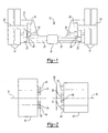
- the inverted portal axle 12 includes a pair of wheel end assemblies 14 supported on an axle housing 16.
- a differential 18 is positioned near one of the wheel end assemblies 14 and axle shafts 20 connect the differential 18 to the outboard wheel end assemblies 14.
- Drive gears 22 are mounted to the outboard ends of the axle shafts 20.
- Driven gears 24 are mounted on drive shafts 26 which support the wheel end assemblies 14.
- a compound gear assembly 28 of the present invention is mounted to the axle housing 16 by a housing shaft 30 to increase torque from the drive gears 22 to the driven gears 24. Gear teeth are not shown in the Figures for clarity.
- Figure 2 illustrates an exploded view of the compound gear assembly 28 from Figure 1 having first 40 and second 46 gears.
- the first gear, or input gear, 40 defines a first axis A and comprises a first set of interlocking features 44.
- the second gear, or output gear, 46 defines a second axis B and comprises a second set of interlocking features 50.
- the first 40 and second 46 gears are mechanically coupled to one another against relative rotation with the interlocking features, which also permit limited relative radial movement enabling the gears to align with one another.
- the first set of interlocking features 44 may be arcuate protrusions having a first outer circumference surface 52 with a first groove 54 located in the surface 52.
- the second set of interlocking features 50 includes arcuate protrusions having a second outer circumference surface 58 with a second groove 60 located in the second outer circumference surface 58.
- the first 54 and second 60 grooves are aligned with one another when assembled to receive a retainer 56 that locks the first 40 and second 46 gears to one another.
- the retainer 56 may be a flexible C-clip with a circular cross-section that seats in a complementary shaped arcuate groove. Other retainer configurations may also be used.
- FIG. 3 shows a cross-section of the first 40 and second 46 gears through the interlocking features.
- Each interlocking feature 44 is an arcuate section defined by the first outer circumference surface 52, in inner surface that receives the housing shaft 30, and opposing faces 62.
- the interlocking features 50 of the second gear 46 are similarly defined.
- the first set of interlocking features 44 and second set of interlocking features 50 are arranged in alternating relationship such that the interlocking features 44 of the first gear 40 engage the interlocking features 50 of the second gear 46.
- the opposing faces 62 define a plane that intersects the axes A, B to better facilitate radial movement of the gears relative to one another.
- the axes A, B may lie within the planes. While each gear is shown as having four arcuate sections, any other suitable number may be used.
- a clearance 64 is located between the interlocking of the gears to provide for relative movement of the gears in relation to one another.
- the clearance 64 is sized to permit relative radial movement between the gears so that the gears will self-align relative to one another and achieve desired engagement to the gears to which they are coupled. However, it is desirable to minimize the clearance 64 to avoid excessive noise between the first 40 and second 46 gears.
- Figure 4 further illustrates a gear train.
- the drive gear 22 defines a third axis C which and is mounted on the drive shaft 20 to provide a torque input. Torque is transmitted though the drive gear 22 to the compound gear assembly 28 for gear reduction and to further transmit the torque to the driven gear 24, which defines a fourth axis D.
- the compound gear assembly 28 may be supported on the housing shaft 30 by bearings, which are not shown.
- the driven gear 24 is mounted on the drive shaft 26, which transmits the reduced torque to an output.
- the clearance 64 provides for relative movement between the first axis A of the first gear 40 and the second axis B of the second gear 46.
- the first axis A is moveable with respect to the third axis C.
- the second axis B defined by the second gear 46 is moveable with respect to the fourth axis D. The relative movement of these axes provides improved engagement between both the drive gear 22 and the first gear 40 and the driven gear 24 and the second gear 46.
Landscapes
- Engineering & Computer Science (AREA)
- General Engineering & Computer Science (AREA)
- Mechanical Engineering (AREA)
- Retarders (AREA)
- Gear Transmission (AREA)
- Gears, Cams (AREA)
Abstract

Description
Claims (13)
- A gear assembly comprising:first and second gears respectively defining first and second axes; andfirst and second interlocking features respectively arranged on said first and second gears engaging one another for transferring torque between said first and second gears, and a clearance arranged between said first and second interlocking features permitting a relative movement between said first and second axes.
- A gear assembly as recited in Claim 1 wherein said first and second interlocking features respectively include first and second protrusions arranged in relation to one another.
- A gear assembly as recited in Claim 3 wherein said first and second protrusions are arcuate sections.
- A gear assembly as recited in Claim 4 wherein said arcuate sections are further defined by faces lying in planes intersecting said first and second axes.
- A gear assembly as recited in any preceding claim wherein said first and second gears define opposing faces transverse to said first and second axes and outer circumference surfaces adjoining said faces.
- A gear assembly as recited in any preceding claim further including a retainer in engagement with said first and second interlocking features securing them to one another.
- A gear assembly as recited in Claim 6 wherein the first and second interlocking features include grooves in surfaces, said retainer installed into said groove.
- A gear assembly as recited in Claim 7 wherein said surfaces are outer circumference surfaces provided by said protrusions.
- A gear assembly as recited in Claim 6 or 7 or 8 wherein said retainer is C-shaped.
- A gear train comprising:a shaft;input and output gears adjacent one another supported on said shaft for rotation thereto, said input and output gears respectively defining first and second axes;first and second interlocking features respectively arranged on said input and output gears engaging one another for transferring torque between said input and output gears, and a clearance arranged between said first and second interlocking features permitting a relative movement between said first and second axes; anda retainer securing said first and second interlocking features to one another.
- A gear assembly or a gear train as recited in any preceding claim wherein said relative movement is radial.
- A gear train as recited in Claim 10 or 11 further comprising:a drive gear defining a third axis substantially parallel to said first axis, said drive gear mounted on a drive shaft and engaging said input gear to transfer torque, said third axis being moveable in relation to said first axis to provide desired engagement between said drive gear and said input gear; anda driven gear defining a fourth axis substantially parallel to said second axis, said driven gear mounted on an driven shaft and engaging said output gear to transfer torque, said fourth axis being moveable in relation to said second axis to provide desired engagement between said output gear and said driven gear.
- A method of assembling a compound gear arrangement comprising the steps of:(a) providing first and second gears including respective interlocking features;(b) aligning said interlocking features adj acent to one another; and(c) securing said interlocking features with a retainer to transfer torque between said first gear and said second gear.
Applications Claiming Priority (2)
| Application Number | Priority Date | Filing Date | Title |
|---|---|---|---|
| US10/428,539 US6868748B2 (en) | 2003-05-02 | 2003-05-02 | Compound gear joining |
| US428539 | 2003-05-02 |
Publications (3)
| Publication Number | Publication Date |
|---|---|
| EP1473476A2 true EP1473476A2 (en) | 2004-11-03 |
| EP1473476A3 EP1473476A3 (en) | 2007-04-25 |
| EP1473476B1 EP1473476B1 (en) | 2008-12-24 |
Family
ID=32990482
Family Applications (1)
| Application Number | Title | Priority Date | Filing Date |
|---|---|---|---|
| EP04252562A Expired - Lifetime EP1473476B1 (en) | 2003-05-02 | 2004-04-30 | Gear assembly |
Country Status (4)
| Country | Link |
|---|---|
| US (1) | US6868748B2 (en) |
| EP (1) | EP1473476B1 (en) |
| CN (1) | CN1550694A (en) |
| DE (1) | DE602004018562D1 (en) |
Cited By (1)
| Publication number | Priority date | Publication date | Assignee | Title |
|---|---|---|---|---|
| CN104948666A (en) * | 2015-06-28 | 2015-09-30 | 芜湖创智机械技术有限公司 | Buffer type transmission gear structure |
Families Citing this family (4)
| Publication number | Priority date | Publication date | Assignee | Title |
|---|---|---|---|---|
| CN101016945B (en) * | 2005-10-15 | 2010-12-08 | 黄振强 | Wide-toothed relay transmission gear |
| CN101963193A (en) * | 2010-09-30 | 2011-02-02 | 安徽巨一自动化装备有限公司 | Turntable floating coupler |
| KR102135973B1 (en) * | 2013-04-02 | 2020-07-21 | 삼성전자주식회사 | Refrigerator |
| KR102843026B1 (en) * | 2022-08-29 | 2025-08-11 | 주식회사 아모텍 | Pinion Gear Unit and Swivel Actuator Using the Same |
Family Cites Families (17)
| Publication number | Priority date | Publication date | Assignee | Title |
|---|---|---|---|---|
| FR817740A (en) * | 1936-02-12 | 1937-09-09 | Coupling for flexible shafts | |
| US2613781A (en) * | 1949-03-18 | 1952-10-14 | Borg Warner | Positive clutch for a power transmission |
| FR1337476A (en) * | 1962-08-03 | 1963-09-13 | Grosdemouge Sa Ets | Coupling device improvements |
| FR2390077A7 (en) * | 1977-05-04 | 1978-12-01 | Ducellier & Cie | Ignition system distributor drive coupling - has two coaxial parts with lugs received in ring slots to be held by circlip in annular groove |
| US4485686A (en) * | 1982-03-25 | 1984-12-04 | Eaton Corporation | Gear retainer |
| GB8305587D0 (en) * | 1983-03-01 | 1983-03-30 | Northern Eng Ind | Toothed gear system |
| US4677868A (en) * | 1986-04-10 | 1987-07-07 | Chrysler Motors Corporation | Transmission vibration viscous damper |
| GB8610756D0 (en) * | 1986-05-02 | 1986-06-11 | Pengilly E A | Power transmission |
| FR2655115B1 (en) * | 1989-11-30 | 1993-01-22 | Valeo | VIBRATION DAMPER, ESPECIALLY FOR A MOTOR VEHICLE. |
| US5214975A (en) * | 1990-11-20 | 1993-06-01 | New Venture Gear, Inc. | Transmission vibration damping |
| JP3034088B2 (en) * | 1991-05-21 | 2000-04-17 | 旭光学工業株式会社 | Slip clutch mechanism |
| JPH0949562A (en) * | 1995-08-08 | 1997-02-18 | Nikko:Kk | Counter gear |
| US5956998A (en) * | 1996-06-06 | 1999-09-28 | Fenelon; Paul J. | Stress reduction gear and apparatus using same |
| US5905927A (en) * | 1996-12-03 | 1999-05-18 | Minolta Co., Ltd. | Image forming apparatus and driving mechanism for image holding member |
| US5904632A (en) | 1997-03-21 | 1999-05-18 | New Venture Gear, Inc. | Full-time four-wheel drive transmission |
| JP3520228B2 (en) | 1999-09-29 | 2004-04-19 | 株式会社日立製作所 | Automobiles and power transmission devices for automobiles |
| US6254196B1 (en) | 1999-12-21 | 2001-07-03 | Thomas A Gee | Axle hub assembly with removable axle shaft |
-
2003
- 2003-05-02 US US10/428,539 patent/US6868748B2/en not_active Expired - Fee Related
-
2004
- 2004-04-30 DE DE602004018562T patent/DE602004018562D1/en not_active Expired - Lifetime
- 2004-04-30 EP EP04252562A patent/EP1473476B1/en not_active Expired - Lifetime
- 2004-05-08 CN CNA2004100381090A patent/CN1550694A/en active Pending
Cited By (1)
| Publication number | Priority date | Publication date | Assignee | Title |
|---|---|---|---|---|
| CN104948666A (en) * | 2015-06-28 | 2015-09-30 | 芜湖创智机械技术有限公司 | Buffer type transmission gear structure |
Also Published As
| Publication number | Publication date |
|---|---|
| DE602004018562D1 (en) | 2009-02-05 |
| US6868748B2 (en) | 2005-03-22 |
| EP1473476A3 (en) | 2007-04-25 |
| CN1550694A (en) | 2004-12-01 |
| US20040216545A1 (en) | 2004-11-04 |
| EP1473476B1 (en) | 2008-12-24 |
Similar Documents
| Publication | Publication Date | Title |
|---|---|---|
| JP4094879B2 (en) | Axle shaft manufacturing method | |
| US7819040B2 (en) | Method for making vehicle axle differential casing and resultant product | |
| US7695392B2 (en) | Differential mechanism assembly | |
| US8221277B2 (en) | Differential provided with a drive wheel | |
| KR101195279B1 (en) | Hub unit, rolling bearing device, producing method for rolling bearing device, and assembling device and assembling method for rolling bearing device | |
| EP1352771A2 (en) | Tandem axle power divider assembly with inboard slip driveshaft connection | |
| CN108656868B (en) | Assembly with clutch collar and method of manufacture | |
| US20120149522A1 (en) | Differential mechanism having multiple case portions | |
| US4723464A (en) | Differential gear assembly for motor vehicles | |
| CN109630644B (en) | Shaft assembly | |
| EP1571373A2 (en) | Helical gear differential | |
| EP0903516A1 (en) | Limited slip differential and improved differential housing assembly therefor | |
| US6379277B1 (en) | Limited slip differential mechanism for an automotive vehicle and method for making the same | |
| US20030108384A1 (en) | Polygonal interface between driving and driven components | |
| EP1777079B1 (en) | Wheel drive unit | |
| CN101395407A (en) | Differential gear housing and method | |
| US5791205A (en) | Anti-rotation spline teeth for differential case | |
| US6868748B2 (en) | Compound gear joining | |
| US7717797B2 (en) | Driveshaft assembly with piloted flange connection | |
| US20120238393A1 (en) | Carrier assembly with threaded adjustment member | |
| WO2004009392A1 (en) | Inter-axle differential having improved bearing arrangement | |
| CN120835964A (en) | Differential and vehicle transmission | |
| CA3229541A1 (en) | Face spline coupling for drive-wheel arrangement | |
| GB2386850A (en) | Method of manufacturing an axle pinion gear | |
| US20050137022A1 (en) | Apparatus and method for friction welded tripod interconnecting shaft |
Legal Events
| Date | Code | Title | Description |
|---|---|---|---|
| PUAI | Public reference made under article 153(3) epc to a published international application that has entered the european phase |
Free format text: ORIGINAL CODE: 0009012 |
|
| AK | Designated contracting states |
Kind code of ref document: A2 Designated state(s): AT BE BG CH CY CZ DE DK EE ES FI FR GB GR HU IE IT LI LU MC NL PL PT RO SE SI SK TR |
|
| AX | Request for extension of the european patent |
Extension state: AL HR LT LV MK |
|
| PUAL | Search report despatched |
Free format text: ORIGINAL CODE: 0009013 |
|
| AK | Designated contracting states |
Kind code of ref document: A3 Designated state(s): AT BE BG CH CY CZ DE DK EE ES FI FR GB GR HU IE IT LI LU MC NL PL PT RO SE SI SK TR |
|
| AX | Request for extension of the european patent |
Extension state: AL HR LT LV MK |
|
| 17P | Request for examination filed |
Effective date: 20071005 |
|
| 17Q | First examination report despatched |
Effective date: 20071115 |
|
| AKX | Designation fees paid |
Designated state(s): DE FR GB IT SE |
|
| GRAP | Despatch of communication of intention to grant a patent |
Free format text: ORIGINAL CODE: EPIDOSNIGR1 |
|
| GRAS | Grant fee paid |
Free format text: ORIGINAL CODE: EPIDOSNIGR3 |
|
| GRAA | (expected) grant |
Free format text: ORIGINAL CODE: 0009210 |
|
| AK | Designated contracting states |
Kind code of ref document: B1 Designated state(s): DE FR GB IT SE |
|
| REG | Reference to a national code |
Ref country code: GB Ref legal event code: FG4D |
|
| REF | Corresponds to: |
Ref document number: 602004018562 Country of ref document: DE Date of ref document: 20090205 Kind code of ref document: P |
|
| REG | Reference to a national code |
Ref country code: SE Ref legal event code: TRGR |
|
| PLBE | No opposition filed within time limit |
Free format text: ORIGINAL CODE: 0009261 |
|
| STAA | Information on the status of an ep patent application or granted ep patent |
Free format text: STATUS: NO OPPOSITION FILED WITHIN TIME LIMIT |
|
| 26N | No opposition filed |
Effective date: 20090925 |
|
| REG | Reference to a national code |
Ref country code: FR Ref legal event code: PLFP Year of fee payment: 13 |
|
| REG | Reference to a national code |
Ref country code: FR Ref legal event code: PLFP Year of fee payment: 14 |
|
| REG | Reference to a national code |
Ref country code: FR Ref legal event code: PLFP Year of fee payment: 15 |
|
| P01 | Opt-out of the competence of the unified patent court (upc) registered |
Effective date: 20230531 |
|
| PGFP | Annual fee paid to national office [announced via postgrant information from national office to epo] |
Ref country code: IT Payment date: 20230419 Year of fee payment: 20 Ref country code: FR Payment date: 20230425 Year of fee payment: 20 Ref country code: DE Payment date: 20230427 Year of fee payment: 20 |
|
| PGFP | Annual fee paid to national office [announced via postgrant information from national office to epo] |
Ref country code: SE Payment date: 20230427 Year of fee payment: 20 |
|
| PGFP | Annual fee paid to national office [announced via postgrant information from national office to epo] |
Ref country code: GB Payment date: 20230427 Year of fee payment: 20 |
|
| REG | Reference to a national code |
Ref country code: DE Ref legal event code: R071 Ref document number: 602004018562 Country of ref document: DE |
|
| REG | Reference to a national code |
Ref country code: GB Ref legal event code: PE20 Expiry date: 20240429 |
|
| REG | Reference to a national code |
Ref country code: SE Ref legal event code: EUG |
|
| PG25 | Lapsed in a contracting state [announced via postgrant information from national office to epo] |
Ref country code: GB Free format text: LAPSE BECAUSE OF EXPIRATION OF PROTECTION Effective date: 20240429 |
|
| PG25 | Lapsed in a contracting state [announced via postgrant information from national office to epo] |
Ref country code: GB Free format text: LAPSE BECAUSE OF EXPIRATION OF PROTECTION Effective date: 20240429 |