EP1473385A1 - Coated cutting tool - Google Patents
Coated cutting tool Download PDFInfo
- Publication number
- EP1473385A1 EP1473385A1 EP04252384A EP04252384A EP1473385A1 EP 1473385 A1 EP1473385 A1 EP 1473385A1 EP 04252384 A EP04252384 A EP 04252384A EP 04252384 A EP04252384 A EP 04252384A EP 1473385 A1 EP1473385 A1 EP 1473385A1
- Authority
- EP
- European Patent Office
- Prior art keywords
- cutting tool
- pvd process
- coating
- cutting
- substrate
- Prior art date
- Legal status (The legal status is an assumption and is not a legal conclusion. Google has not performed a legal analysis and makes no representation as to the accuracy of the status listed.)
- Withdrawn
Links
- 238000005520 cutting process Methods 0.000 title claims abstract description 111
- 238000000576 coating method Methods 0.000 claims abstract description 58
- 239000011248 coating agent Substances 0.000 claims abstract description 57
- 238000000034 method Methods 0.000 claims abstract description 48
- 239000000758 substrate Substances 0.000 claims abstract description 45
- 239000002245 particle Substances 0.000 claims abstract description 38
- 239000011195 cermet Substances 0.000 claims abstract description 20
- IJGRMHOSHXDMSA-UHFFFAOYSA-N Atomic nitrogen Chemical compound N#N IJGRMHOSHXDMSA-UHFFFAOYSA-N 0.000 claims abstract description 16
- 230000003746 surface roughness Effects 0.000 claims abstract description 15
- OKTJSMMVPCPJKN-UHFFFAOYSA-N Carbon Chemical compound [C] OKTJSMMVPCPJKN-UHFFFAOYSA-N 0.000 claims abstract description 8
- 229910052799 carbon Inorganic materials 0.000 claims abstract description 8
- 229910052757 nitrogen Inorganic materials 0.000 claims abstract description 8
- 229910052710 silicon Inorganic materials 0.000 claims abstract description 8
- ZOXJGFHDIHLPTG-UHFFFAOYSA-N Boron Chemical compound [B] ZOXJGFHDIHLPTG-UHFFFAOYSA-N 0.000 claims abstract description 4
- XUIMIQQOPSSXEZ-UHFFFAOYSA-N Silicon Chemical compound [Si] XUIMIQQOPSSXEZ-UHFFFAOYSA-N 0.000 claims abstract description 4
- QVGXLLKOCUKJST-UHFFFAOYSA-N atomic oxygen Chemical compound [O] QVGXLLKOCUKJST-UHFFFAOYSA-N 0.000 claims abstract description 4
- 229910052796 boron Inorganic materials 0.000 claims abstract description 4
- 229910052760 oxygen Inorganic materials 0.000 claims abstract description 4
- 239000001301 oxygen Substances 0.000 claims abstract description 4
- 239000010703 silicon Substances 0.000 claims abstract description 4
- 239000000463 material Substances 0.000 claims description 33
- 238000003754 machining Methods 0.000 claims description 12
- ATJFFYVFTNAWJD-UHFFFAOYSA-N Tin Chemical compound [Sn] ATJFFYVFTNAWJD-UHFFFAOYSA-N 0.000 claims description 9
- 230000002035 prolonged effect Effects 0.000 abstract description 3
- 239000010410 layer Substances 0.000 description 41
- 230000000052 comparative effect Effects 0.000 description 30
- 238000005240 physical vapour deposition Methods 0.000 description 19
- 238000011156 evaluation Methods 0.000 description 15
- 238000012360 testing method Methods 0.000 description 8
- 229910010037 TiAlN Inorganic materials 0.000 description 6
- 230000000694 effects Effects 0.000 description 5
- 238000007733 ion plating Methods 0.000 description 3
- 238000004901 spalling Methods 0.000 description 3
- 238000012937 correction Methods 0.000 description 2
- 230000007423 decrease Effects 0.000 description 2
- 150000001247 metal acetylides Chemical class 0.000 description 2
- 238000003466 welding Methods 0.000 description 2
- 229910003178 Mo2C Inorganic materials 0.000 description 1
- 229910009043 WC-Co Inorganic materials 0.000 description 1
- 230000002159 abnormal effect Effects 0.000 description 1
- 239000002173 cutting fluid Substances 0.000 description 1
- 238000010586 diagram Methods 0.000 description 1
- 229910003460 diamond Inorganic materials 0.000 description 1
- 239000010432 diamond Substances 0.000 description 1
- 239000010419 fine particle Substances 0.000 description 1
- 238000012423 maintenance Methods 0.000 description 1
- 239000000203 mixture Substances 0.000 description 1
- 238000012986 modification Methods 0.000 description 1
- 230000004048 modification Effects 0.000 description 1
- 230000002265 prevention Effects 0.000 description 1
- 230000035939 shock Effects 0.000 description 1
- 239000002356 single layer Substances 0.000 description 1
Images


Classifications
-
- B—PERFORMING OPERATIONS; TRANSPORTING
- B23—MACHINE TOOLS; METAL-WORKING NOT OTHERWISE PROVIDED FOR
- B23B—TURNING; BORING
- B23B27/00—Tools for turning or boring machines; Tools of a similar kind in general; Accessories therefor
- B23B27/14—Cutting tools of which the bits or tips or cutting inserts are of special material
-
- C—CHEMISTRY; METALLURGY
- C23—COATING METALLIC MATERIAL; COATING MATERIAL WITH METALLIC MATERIAL; CHEMICAL SURFACE TREATMENT; DIFFUSION TREATMENT OF METALLIC MATERIAL; COATING BY VACUUM EVAPORATION, BY SPUTTERING, BY ION IMPLANTATION OR BY CHEMICAL VAPOUR DEPOSITION, IN GENERAL; INHIBITING CORROSION OF METALLIC MATERIAL OR INCRUSTATION IN GENERAL
- C23C—COATING METALLIC MATERIAL; COATING MATERIAL WITH METALLIC MATERIAL; SURFACE TREATMENT OF METALLIC MATERIAL BY DIFFUSION INTO THE SURFACE, BY CHEMICAL CONVERSION OR SUBSTITUTION; COATING BY VACUUM EVAPORATION, BY SPUTTERING, BY ION IMPLANTATION OR BY CHEMICAL VAPOUR DEPOSITION, IN GENERAL
- C23C14/00—Coating by vacuum evaporation, by sputtering or by ion implantation of the coating forming material
- C23C14/02—Pretreatment of the material to be coated
- C23C14/024—Deposition of sublayers, e.g. to promote adhesion of the coating
-
- C—CHEMISTRY; METALLURGY
- C23—COATING METALLIC MATERIAL; COATING MATERIAL WITH METALLIC MATERIAL; CHEMICAL SURFACE TREATMENT; DIFFUSION TREATMENT OF METALLIC MATERIAL; COATING BY VACUUM EVAPORATION, BY SPUTTERING, BY ION IMPLANTATION OR BY CHEMICAL VAPOUR DEPOSITION, IN GENERAL; INHIBITING CORROSION OF METALLIC MATERIAL OR INCRUSTATION IN GENERAL
- C23C—COATING METALLIC MATERIAL; COATING MATERIAL WITH METALLIC MATERIAL; SURFACE TREATMENT OF METALLIC MATERIAL BY DIFFUSION INTO THE SURFACE, BY CHEMICAL CONVERSION OR SUBSTITUTION; COATING BY VACUUM EVAPORATION, BY SPUTTERING, BY ION IMPLANTATION OR BY CHEMICAL VAPOUR DEPOSITION, IN GENERAL
- C23C14/00—Coating by vacuum evaporation, by sputtering or by ion implantation of the coating forming material
- C23C14/02—Pretreatment of the material to be coated
- C23C14/028—Physical treatment to alter the texture of the substrate surface, e.g. grinding, polishing
-
- C—CHEMISTRY; METALLURGY
- C23—COATING METALLIC MATERIAL; COATING MATERIAL WITH METALLIC MATERIAL; CHEMICAL SURFACE TREATMENT; DIFFUSION TREATMENT OF METALLIC MATERIAL; COATING BY VACUUM EVAPORATION, BY SPUTTERING, BY ION IMPLANTATION OR BY CHEMICAL VAPOUR DEPOSITION, IN GENERAL; INHIBITING CORROSION OF METALLIC MATERIAL OR INCRUSTATION IN GENERAL
- C23C—COATING METALLIC MATERIAL; COATING MATERIAL WITH METALLIC MATERIAL; SURFACE TREATMENT OF METALLIC MATERIAL BY DIFFUSION INTO THE SURFACE, BY CHEMICAL CONVERSION OR SUBSTITUTION; COATING BY VACUUM EVAPORATION, BY SPUTTERING, BY ION IMPLANTATION OR BY CHEMICAL VAPOUR DEPOSITION, IN GENERAL
- C23C30/00—Coating with metallic material characterised only by the composition of the metallic material, i.e. not characterised by the coating process
- C23C30/005—Coating with metallic material characterised only by the composition of the metallic material, i.e. not characterised by the coating process on hard metal substrates
-
- Y—GENERAL TAGGING OF NEW TECHNOLOGICAL DEVELOPMENTS; GENERAL TAGGING OF CROSS-SECTIONAL TECHNOLOGIES SPANNING OVER SEVERAL SECTIONS OF THE IPC; TECHNICAL SUBJECTS COVERED BY FORMER USPC CROSS-REFERENCE ART COLLECTIONS [XRACs] AND DIGESTS
- Y10—TECHNICAL SUBJECTS COVERED BY FORMER USPC
- Y10T—TECHNICAL SUBJECTS COVERED BY FORMER US CLASSIFICATION
- Y10T428/00—Stock material or miscellaneous articles
- Y10T428/25—Web or sheet containing structurally defined element or component and including a second component containing structurally defined particles
-
- Y—GENERAL TAGGING OF NEW TECHNOLOGICAL DEVELOPMENTS; GENERAL TAGGING OF CROSS-SECTIONAL TECHNOLOGIES SPANNING OVER SEVERAL SECTIONS OF THE IPC; TECHNICAL SUBJECTS COVERED BY FORMER USPC CROSS-REFERENCE ART COLLECTIONS [XRACs] AND DIGESTS
- Y10—TECHNICAL SUBJECTS COVERED BY FORMER USPC
- Y10T—TECHNICAL SUBJECTS COVERED BY FORMER US CLASSIFICATION
- Y10T428/00—Stock material or miscellaneous articles
- Y10T428/31504—Composite [nonstructural laminate]
- Y10T428/31652—Of asbestos
- Y10T428/31663—As siloxane, silicone or silane
Definitions
- the present invention relates to a cutting tool coated using the physical vapor deposition (PVD) process that has excellent sharpness and can produce a product having a good machined surface and high geometrical precision, and particularly to a cutting tool coated using the PVD process to be used in a machining field that requires high precision, such as electronics parts.
- PVD physical vapor deposition
- the turning work for parts such as electronics parts, clock parts, and camera parts requires high precision in geometrical precision and in the surface roughness of a machined surface.
- an indexable insert coated with TiAlN, TiCN, or a similar material has widely been used as the cutting tool for such high-precision parts.
- An ordinary coated indexable insert is covered with a coating having a thickness of 3 to 5 ⁇ m or so.
- the amount of feed and the depth of cut are small in many cases. This condition tends to cause the coating to suffer chipping. Once the chipping develops, the tool cannot be used anymore in many cases because the surface roughness increases or the amount of tool correction increases. Therefore, an ordinary coated indexable insert cannot be used reliably as the cutting tool for the high-precision machining.
- the use of the built-up edge may cause the tool to chip when the built-up edge falls off.
- the TiCN-based coating has a lower hardness than that of a coating such as a TiAlN-based-coating, it would wear away in the early stage, exposing the substrate. As a result, the built-up edge grows more than necessary to reduce the dimensional precision and cause other problems.
- the cutting edge when the cutting edge is provided with a round-type honing or a chamfered corner to prevent the spalling of the TiAlN-based-coating, the cutting resistance would increase. This increase tends to cause the work material to weld, making the machined surface whitish and increasing the surface roughness and dimensional variations.
- An object of the present invention is to offer a cutting tool coated using the PVD process that can produce a product having high geometrical precision and a good machined surface and can continue the cutting work for a prolonged time.
- the present invention achieves the foregoing object by offering the following cutting tool coated using the PVD process.
- the cutting tool comprises:
- the coating may have the following features:
- the coating may further comprise an undermost layer that:
- the coating may have a remaining compressional stress of -3.0 to 0 GPa.
- the coating may have at its surface portion macroparticles with a density of at most 10 particles per square millimeter, where only the particles having a diameter of at least 5 ⁇ m are counted.
- the substrate may be composed of cemented carbide containing 3 to 12 wt. % Co and having a Vickers hardness of 14 to 22 GPa.
- the substrate may be composed of cermet containing 5 to 12 wt. % Co and having a Vickers hardness of 14 to 22 GPa.
- the present invention's cutting tool coated using the PVD process is suitable as an indexable insert for turning work, such as an indexable insert for inside-diameter turning work, and useful as a tool for machining hard disk-related parts.
- the present invention's cutting tool coated using the PVD process can produce a product having small dimensional variations and high precision with a good machined surface free from a whitish portion and can continue the cutting work for a prolonged time. Therefore, the cutting tool is useful as a tool for precise machining and, particularly, can be used for the turning work of parts such as electronics parts, clock parts, and camera parts, which require high precision of the order of micrometer.
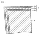
- the present invention's cutting tool coated using the PVD process comprises a substrate 1 composed of cemented carbide or cermet and a coating 2 formed over the substrate 1 using the PVD process.
- the coating 2 comprises an outer layer 2a and an inner layer 2b.
- the total thickness of the inner and outer layers is at most 2.0 ⁇ m.
- the inner layer comprises (a) at least one member selected from the group consisting of the 4a-group elements, the 5a-group elements, the 6a-group elements, Al, and Si and (b) at least one member selected from the group consisting of carbon, nitrogen, and oxygen.
- the outer layer comprises (a) at least one member selected from the group consisting of boron, silicon, carbon, and nitrogen and (b) Ti.
- the substrate has a a surface roughness, Ra, of at most 0.3 ⁇ m.
- the substrate is structured by hard particles having an average particle diameter of 0.3 to 1.5 ⁇ m.
- the cutting part has a sharp edge with a positive shape.
- Figure 4 shows a cross section showing a portion in the vicinity of a cutting edge 40 at the time when a bottom face 43 of the cutting part is held horizontally.
- the term "positive shape” means that the wedge angle ⁇ of the cutting edge 40 is less than 90 degrees.
- the cutting part have a rake face 41 whose rake angle "a" is at least 0 degree, a frank 42 whose clearance angle "b” is at least 5 degrees, and a wedge angle, ⁇ , of at most 80 degrees.
- the term “sharp edge” is used to mean an extremely sharp shape of the cutting part having a cutting edge with a radius of at most 0.01 mm.
- the “sharp edge” also includes the shape of a cutting part in which breakage or chipping is developed when the rake face 41 and the frank 42 are polished.
- the present invention's cutting tool coated using the PVD process has the above-described features, it has excellent anti-chipping property, wear resistance, and geometrical precision. It also is superior in having a small magnitude of surface roughness of the machined surface. Consequently, it can be used suitably as a cutting tool for precise machining.
- the total thickness of the inner and outer layers be at most 2.0 ⁇ m, more desirably at most 1.5 ⁇ m.
- the total thickness of the inner and outer layers be at least 0.5 ⁇ m.
- the outer layer is required to wear normally at the early stage of the cutting in order to suppress the abnormal chipping of the coating so that the increase in the surface roughness and in the amount of tool correction can be suppressed.
- the coating have an inner layer thicker than the outer layer. More specifically, it is desirable that the inner layer be thicker than the outer layer by 0.1 to 0.8 ⁇ m.
- the coating have an inner layer having a hardness higher than that of the outer layer.
- the inner layer having high hardness increases the wear resistance, exercising the effect of increasing the tool life significantly. More specifically, it is desirable that the inner layer have a hardness about 1.05 to about 2 times that of the outer layer, more desirably 1.1 to 1.5 times.
- the outer layer be composed of TiN, for example.
- the coating is formed using the PVD process.
- the PVD process produces remaining compressional stress in the coating. Consequently, even when the substrate has the sharp-edge shape, a good cutting performance can be achieved without reducing the strength of the cutting edge.
- the arc ion-plating method is employed suitably, for example. It is desirable the remaining compressional stress in the coating be controlled to fall in the range of -3.0 to 0 GPa to achieve good bonding strength without the self-destruction of the coating, more desirably in the range of -2.8 to -0.5 GPa.
- the coating 2 be provided with an undermost layer 2c at the interface with the substrate 1. In this case, it is desirable that the undermost layer 2c comprise TiN or CrN and have a thickness of at most 0.5 ⁇ m, more desirably at most 0.3 ⁇ m.
- the coating formed using the arc ion-plating method has hard particles known as macroparticles at its surface portion.
- macroparticles reduce their size and density, the cutting resistance is reduced, enabling the prevention of the welding of the work material.
- the tool life is increased, and the machined-surface quality of the work material is improved.
- the macroparticles have a density of at most 10 particles per square millimeter, where only the particles having a diameter of at least 5 ⁇ m are counted. If it is more than 10 particles per square millimeter, the work material would weld to the macroparticles, increasing the cutting resistance. As a result, the tool life is deceased, and the machined-surface quality of the work material is degraded, which must be prevented.
- the density of the macroparticles can be measured by the observation under a scanning electron microscope (SEM). First, the surface of the specimen is photographed with a magnification of at least 1,000X. Then, the density can be obtained by counting the number of macroparticles on the photograph.
- SEM scanning electron microscope
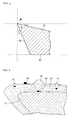
- Figure 5 schematically shows the process of the growth of macroparticles 51 by using a cross section of the coating.
- molten particles flying from the target adhere to the surface of the coating to form deposited particles 54.
- Observation of the surface of the coating under an SEM can confirm the presence of round deposited particles having different diameters.
- these deposited particles are undesirable in the present invention.
- the flying deposited particles 54 adhere during the growing process of the coating. Therefore, it is likely that as shown in Fig. 5, the deposited particles 54 lie at various thicknesswise positions in the coating 53.
- the cutting tool of the present invention has a substrate composed of cemented carbide or cermet.
- the composition of the cemented carbide or cermet is not specifically limited.
- the cemented carbide may be either K-type cemented carbide (WC-Co-based one) or P-type cemented carbide (WC- ⁇ -Co-based one).
- the cermet may be TiC-Ni-Mo 2 C-based cermet, for example.
- Ra surface roughness
- the hard particles structuring the substrate are fine particles because they can prevent the increase in the machined-surface roughness due to the falling-off of the particles and facilitate controlling the surface roughness Ra to at most 0.3 ⁇ m. More specifically, it is desirable that the hard particles have an average particle diameter of 0.3 to 1.5 ⁇ m, more desirably 0.5 to 1.3 ⁇ m.
- the average particle diameter of the hard particles is calculated through the following process.
- a cut section of the substrate is treated by lapping to photograph it under an SEM at 10,000 power.
- Figure 6 schematically shows an example of a cut section of the substrate photographed under an SEM. As shown in Fig. 6, a line is drawn randomly on the photograph.
- the cemented carbide When the substrate is composed of cemented carbide, it is desirable that the cemented carbide contain at least 3 wt. % Co to prevent the cemented carbide from becoming brittle, more desirably at least 5 wt. % Co. On the other hand, it is desirable that the cemented carbide contain at most 12 wt. % Co to increase the hardness, more desirably at most 10 wt. % Co. It is desirable that the cemented carbide have high hardness in Vickers hardness to maintain the wear resistance after the substrate is exposed. More specifically, it is desirable that the Vickers hardness be 14 to 22 GPa, more desirably 15 to 22 GPa.
- the cermet when the substrate is composed of cermet, it is desirable that the cermet contain at least 5 wt. % Co to prevent the cermet from becoming brittle, more desirably at least 8 wt. % Co. On the other hand, it is desirable that the cermet contain at most 12 wt. % Co to increase the hardness, more desirably at most 10 wt. % Co. It is desirable that the cermet have high hardness in Vickers hardness to maintain the wear resistance after the substrate is exposed. More specifically, it is desirable that the Vickers hardness be 14 to 22 GPa, more desirably 15 to 22 GPa.
- the cutting tool of the present invention comprising the foregoing substrate and coating
- the surface roughness Ra of the machined surface is reduced to at most 0.15 ⁇ m. Consequently, a good machined-surface quality free from a whitish portion can be obtained, and the dimensional variation in the work material is reduced. Therefore, the cutting tool can be used suitably as an indexable insert for turning work, such as an indexable insert for inside-diameter turning work, for example.
- it is suitable as a cutting tool for machining hard disk-related parts, which require high-precision machining.
- the substrate used for the samples was cemented carbide which had WC having an average particle diameter of 1.0 ⁇ m, which had a Co content of 10 wt. %, and which had a Vickers hardness of 15 GPa.
- indexable inserts having the shape as shown in Fig. 2 were produced.
- the indexable insert had a diamond shape with a vertex angle of 55 degrees, had a flank with a clearance angle of 7 degrees, and had a rake face with a rake angle of 20 degrees.
- the polished substrate had a cutting part with an incisive sharp edge having a positive shape.
- the rake face and the flank had a surface roughness, Ra, of 0.2 ⁇ m.
- Various coatings were used as shown in Table I. The coating was formed over the substrate using the arc ion-plating method, which is an ordinary method as the PVD process. The indexable insert was attached to an ordinary holder. Under this condition, outside-diameter turning work was performed to evaluate the cutting performance. The evaluation of the cutting performance was conducted under the following conditions:
- the cutting tool of each example cut 1,000 work materials. After the cutting of 10, 100, 500, and 1,000 work materials, the machined-surface quality and the dimensional variation were evaluated. The machined-surface quality was judged by visually observing the machined work material. The evaluation results are shown in Table II, in which "o ⁇ " shows that the surface was particularly good, “ ⁇ ” shows that the surface was good, and “ ⁇ ” shows that the surface became whitish. The dimensional variation was judged by measuring the outside diameter of 10 work materials obtained immediately before the completion of the cutting of 10, 100, 500, and 1,000 work materials.
- Coating Machined-surface quality 10 100 500 1,000
- Example 1 o ⁇ o ⁇ o ⁇ o ⁇ o ⁇ Example 2 o ⁇ ⁇ ⁇ ⁇ Example 3 o ⁇ o ⁇ o ⁇ o ⁇ Example 4 o ⁇ o ⁇ o ⁇ ⁇ ⁇ Example 5 o ⁇ o ⁇ ⁇ ⁇ Example 6 o ⁇ o ⁇ ⁇ ⁇ Example 7 o ⁇ o ⁇ o o o ⁇ Example 8 o ⁇ ⁇ ⁇ ⁇ Example 9 o ⁇ ⁇ ⁇ ⁇ Example 10 ⁇ ⁇ ⁇ ⁇ Example 11 o ⁇ o ⁇ o ⁇ ⁇ Example 12 o ⁇ ⁇ ⁇ ⁇ Comparative example 1 ⁇ ⁇ ⁇ ⁇ Comparative example 2 ⁇ ⁇ ⁇ ⁇ Comparative example 3 ⁇ ⁇ ⁇ ⁇ Comparative example 4 ⁇ ⁇ ⁇ ⁇ Comparative example 5 ⁇ ⁇ ⁇ ⁇ Comparative example
- Comparative examples had a coating as shown in Table I. Only the indexable insert of Comparative example 6 had a negative shape with a rake angle of 0 degree, a clearance angle of 0 degree, and a wedge angle of 90 degrees. Except for these conditions, the machined-surface quality and the dimensional variation were evaluated by using methods similar to those used for Examples 1 to 12. The evaluation results of the machined-surface quality are also shown in Table II, and those of the dimensional variation are also shown in Table III. As can be seen from the results in Table II, Comparative example 1, which had no outer layer, and Comparative example 3, which had an outer layer composed of TiAlN, developed chipping in the coating and made the machined surface whitish in the early stage of the cutting test.
- Comparative example 2 which had a coating formed by a single layer composed of TiN, lacked wear resistance. As a result, its coating wore away in the early stage of the cutting test, exposing the cemented carbide and making the machined surface whitish. Comparative examples 4 and 5, which had an inner layer and an outer layer whose total thickness exceeded 2.0 ⁇ m, developed chipping. As a result, the machined surface was already whitish at the time of cutting the 500th work material. Comparative example 6, whose cutting part had a negative shape, had a high cutting resistance. As a result, the machined surface became whitish and the dimensional variation was large in the early stage of the cutting test.
- Comparative examples showed a good result in the dimensional variation while the number of cutting work materials was small, as in the case of the machined-surface quality. However, as the number increased, the coating developed chipping and the cemented carbide was exposed, increasing the dimensional variation.
- This cutting evaluation test proved that the present invention can prevent the substrate from exposing due to wearing while securely maintaining the sharpness of the cutting tool. This feature enables the maintenance of the good machined-surface quality for a long period and decreases the dimensional variation.
- indexable inserts were produced by using the same procedure as used in Example 1, except for that the cemented carbides as shown in Table IV were used.
- the produced indexable inserts were subjected to the cutting of 1,000 work materials to evaluate the machined-surface quality and the dimensional variation. The results of the evaluation are also shown in Table IV.
- the evaluation method is the same as for Example 1.
- Indexable inserts were produced by using the same procedure as used in Example 1, except for that the cemented carbides as shown in Table IV were used.
- the produced indexable inserts were subjected to the cutting of 1,000 work materials to evaluate the machined-surface quality and the dimensional variation.
- the results of the evaluation are also shown in Table IV.
- the evaluation method is the same as for Example 1.
- the cemented carbide as the substrate was structured by hard particles having an average particle diameter of more than 1.5 ⁇ m. As a result, the machined-surface quality was poor and the dimensional variation was large.
- indexable inserts were produced by using the same procedure as used in Example 1, except for that as the cermet, TiCN shown in Table V were used.
- the produced indexable inserts were subjected to the cutting of 1,000 work materials to evaluate the machined-surface quality and the dimensional variation. The results of the evaluation are also shown in Table V.
- the evaluation method is the same as for Example 1.
- An indexable insert was produced by using the same procedure as used in Example 1, except for that as the cermet as the substrate, TiCN shown in Table V was used.
- the produced indexable insert was subjected to the cutting of 1,000 work materials to evaluate the machined-surface quality and the dimensional variation. The results of the evaluation are also shown in Table V.
- the evaluation method is the same as for Example 1.
- the hard particles had an average particle diameter as large as 2.5 ⁇ m; and the substrate had low hardness. As a result, the tool tended to wear in the early stage of the cutting test, the machined-surface quality was poor, and the dimensional variation was large.
- the cutting evaluation test was conducted by using the outside-diameter turning work.
- various cutting tools were subjected to not only outside-diameter turning work but also other turning work.
- the cutting tool of the present invention exercised its excellent performance in a field that requires highly precise machining, such as hard disk-related parts.
- the indexable insert shown in Fig. 3 comprises a cutting edge 3 at the top and a holding portion 4 that is to be held by a holder to be used as an inside-diameter turning tool.
Landscapes
- Chemical & Material Sciences (AREA)
- Engineering & Computer Science (AREA)
- Mechanical Engineering (AREA)
- Chemical Kinetics & Catalysis (AREA)
- Materials Engineering (AREA)
- Metallurgy (AREA)
- Organic Chemistry (AREA)
- Cutting Tools, Boring Holders, And Turrets (AREA)
- Physical Vapour Deposition (AREA)
Abstract
The present invention's cutting tool coated using the PVD process can cut with high geometrical precision, produce a good machined surface, and cut for a prolonged time. Its substrate (1) is composed of cemented carbide or cermet, has a surface roughness, Ra, of at most 0.3 mu m, is structured by hard particles having an average particle diameter of 0.3 to 1.5 mu m, and has a cutting part having a sharp positive edge. Its coating (2) is formed over the substrate using the PVD process and comprises an inner layer (2b) and an outer layer (2a). The total thickness of the inner and outer layers is at most 2.0 mu m. The inner layer comprises (a) at least one of the 4a-, 5a-, 6a-group elements, Al, and Si and (b) at least one of carbon, nitrogen, and oxygen. The outer layer comprises (c) at least one of boron, silicon, carbon, and nitrogen and (d) Ti. <IMAGE>
Description
The present invention relates to a cutting tool coated using the physical vapor
deposition (PVD) process that has excellent sharpness and can produce a
product having a good machined surface and high geometrical precision, and
particularly to a cutting tool coated using the PVD process to be used in a machining
field that requires high precision, such as electronics parts.
Generally, the turning work for parts such as electronics parts, clock parts,
and camera parts requires high precision in geometrical precision and in the
surface roughness of a machined surface. In addition, the recent miniaturization
of electronics and other devices has been requiring higher precision in
geometrical precision and surface roughness for their parts. As the cutting tool
for such high-precision parts, an indexable insert coated with TiAlN, TiCN, or
a similar material has widely been used. An ordinary coated indexable insert
is covered with a coating having a thickness of 3 to 5 µm or so. In the cutting
of high-precision parts, the amount of feed and the depth of cut are small in
many cases. This condition tends to cause the coating to suffer chipping. Once
the chipping develops, the tool cannot be used anymore in many cases because
the surface roughness increases or the amount of tool correction increases.
Therefore, an ordinary coated indexable insert cannot be used reliably as the
cutting tool for the high-precision machining.
To solve the above-described problem, published Japanese patent application
Tokukai 2001-277004 has disclosed a method in which a substrate having a
small magnitude of surface roughness is covered with a TiCN-based coating
having a thickness of at most 2 µm. This method is intended to produce a stable
built-up edge at the time of cutting so that it can protect the cutting edge
to stabilize the machined dimension. There is another problem. When a sharp
edge is covered with a highly hard TiAlN-based-coating, a high remaining compressional
stress in the coating tends to spall the coating. As a result, the
coating suffer spalling even with a slight shock. To solve this problem,
published Japanese patent application Tokukai 2002-160108 has disclosed a
method in which a TiAlN-based-coating is stably formed over a cutting edge by
providing it with a round-type honing or a chamfered corner each having a
width of 0.1 to 20 µm.
However, in the method of protecting the cutting edge with a built-up edge
by forming a TiCN-based coating having a thickness of at most 2 µm to prevent
the coating from chipping, the use of the built-up edge may cause the tool
to chip when the built-up edge falls off. In addition, because the TiCN-based
coating has a lower hardness than that of a coating such as a
TiAlN-based-coating, it would wear away in the early stage, exposing the substrate.
As a result, the built-up edge grows more than necessary to reduce the
dimensional precision and cause other problems. On the other hand, when the
cutting edge is provided with a round-type honing or a chamfered corner to
prevent the spalling of the TiAlN-based-coating, the cutting resistance would
increase. This increase tends to cause the work material to weld, making the
machined surface whitish and increasing the surface roughness and dimensional
variations.
An object of the present invention is to offer a cutting tool coated using the
PVD process that can produce a product having high geometrical precision and
a good machined surface and can continue the cutting work for a prolonged
time.
The present invention achieves the foregoing object by offering the following
cutting tool coated using the PVD process. The cutting tool comprises:
Having these features, the present invention's cutting tool coated using the PVD process is suitable as a tool for precise machining.
According to one aspect of the present invention, the coating may have the
following features:
As another aspect, the coating may further comprise an undermost layer that:
As yet another aspect, the coating may have a remaining compressional stress
of -3.0 to 0 GPa. As yet another aspect, the coating may have at its surface
portion macroparticles with a density of at most 10 particles per square millimeter,
where only the particles having a diameter of at least 5 µm are
counted.
According to yet another aspect of the present invention, the substrate may
be composed of cemented carbide containing 3 to 12 wt. % Co and having a
Vickers hardness of 14 to 22 GPa. As yet another aspect, the substrate may be
composed of cermet containing 5 to 12 wt. % Co and having a Vickers hardness
of 14 to 22 GPa.
The present invention's cutting tool coated using the PVD process is suitable
as an indexable insert for turning work, such as an indexable insert for inside-diameter
turning work, and useful as a tool for machining hard
disk-related parts.
The present invention's cutting tool coated using the PVD process can produce
a product having small dimensional variations and high precision with a
good machined surface free from a whitish portion and can continue the cutting
work for a prolonged time. Therefore, the cutting tool is useful as a tool
for precise machining and, particularly, can be used for the turning work of
parts such as electronics parts, clock parts, and camera parts, which require
high precision of the order of micrometer.
In the drawing:
As shown in Fig. 1, the present invention's cutting tool coated using the PVD
process comprises a substrate 1 composed of cemented carbide or cermet and a
coating 2 formed over the substrate 1 using the PVD process. The coating 2
comprises an outer layer 2a and an inner layer 2b. The total thickness of the
inner and outer layers is at most 2.0 µm. The inner layer comprises (a) at
least one member selected from the group consisting of the 4a-group elements,
the 5a-group elements, the 6a-group elements, Al, and Si and (b) at least one
member selected from the group consisting of carbon, nitrogen, and oxygen.
The outer layer comprises (a) at least one member selected from the group consisting
of boron, silicon, carbon, and nitrogen and (b) Ti. The substrate has a
a surface roughness, Ra, of at most 0.3 µm. The substrate is structured by
hard particles having an average particle diameter of 0.3 to 1.5 µm. The cutting
part has a sharp edge with a positive shape.
Figure 4 shows a cross section showing a portion in the vicinity of a cutting
edge 40 at the time when a bottom face 43 of the cutting part is held horizontally.
As can be seen from Fig. 4, the term "positive shape" means that the
wedge angle of the cutting edge 40 is less than 90 degrees. In particular, it
is desirable that the cutting part have a rake face 41 whose rake angle "a" is at
least 0 degree, a frank 42 whose clearance angle "b" is at least 5 degrees, and a
wedge angle, , of at most 80 degrees. In the above description, the term
"sharp edge" is used to mean an extremely sharp shape of the cutting part
having a cutting edge with a radius of at most 0.01 mm. However, the "sharp
edge" also includes the shape of a cutting part in which breakage or chipping
is developed when the rake face 41 and the frank 42 are polished.
Because the present invention's cutting tool coated using the PVD process
has the above-described features, it has excellent anti-chipping property, wear
resistance, and geometrical precision. It also is superior in having a small
magnitude of surface roughness of the machined surface. Consequently, it can
be used suitably as a cutting tool for precise machining.
To form a coating without spalling even when the substrate has a cutting
part having a sharp edge with a positive shape, it is desirable that the total
thickness of the inner and outer layers be at most 2.0 µm, more desirably at
most 1.5 µm. On the other hand, to obtain a good machined surface and excellent
geometrical precision, it is desirable that the total thickness of the inner
and outer layers be at least 0.5 µm. In the coating, the outer layer is required
to wear normally at the early stage of the cutting in order to suppress
the abnormal chipping of the coating so that the increase in the surface
roughness and in the amount of tool correction can be suppressed. To meet this
requirement, it is desirable that the coating have an inner layer thicker than
the outer layer. More specifically, it is desirable that the inner layer be thicker
than the outer layer by 0.1 to 0.8 µm.
To meet the above-described requirement of the normal wearing of the outer
layer in the early stage, it is also desirable that the coating have an inner
layer having a hardness higher than that of the outer layer. The inner layer
having high hardness increases the wear resistance, exercising the effect of
increasing the tool life significantly. More specifically, it is desirable that the
inner layer have a hardness about 1.05 to about 2 times that of the outer layer,
more desirably 1.1 to 1.5 times. To meet this requirement, it is desirable that
the outer layer be composed of TiN, for example.
The coating is formed using the PVD process. The PVD process produces
remaining compressional stress in the coating. Consequently, even when the
substrate has the sharp-edge shape, a good cutting performance can be
achieved without reducing the strength of the cutting edge. As the PVD process,
the arc ion-plating method is employed suitably, for example. It is desirable
the remaining compressional stress in the coating be controlled to fall in
the range of -3.0 to 0 GPa to achieve good bonding strength without the
self-destruction of the coating, more desirably in the range of -2.8 to -0.5 GPa.
In addition, to increase the bonding strength of the coating, it is desirable that
as shown in Fig. 1, the coating 2 be provided with an undermost layer 2c at the
interface with the substrate 1. In this case, it is desirable that the undermost
layer 2c comprise TiN or CrN and have a thickness of at most 0.5 µm, more
desirably at most 0.3 µm.
The coating formed using the arc ion-plating method has hard particles
known as macroparticles at its surface portion. As the macroparticles reduce
their size and density, the cutting resistance is reduced, enabling the prevention
of the welding of the work material. As a result, the tool life is increased,
and the machined-surface quality of the work material is improved. It is desirable
that the macroparticles have a density of at most 10 particles per
square millimeter, where only the particles having a diameter of at least 5 µm
are counted. If it is more than 10 particles per square millimeter, the work
material would weld to the macroparticles, increasing the cutting resistance.
As a result, the tool life is deceased, and the machined-surface quality of the
work material is degraded, which must be prevented.
The density of the macroparticles can be measured by the observation under
a scanning electron microscope (SEM). First, the surface of the specimen is
photographed with a magnification of at least 1,000X. Then, the density can be
obtained by counting the number of macroparticles on the photograph.
Figure 5 schematically shows the process of the growth of macroparticles 51
by using a cross section of the coating. During the process of forming a coating
53 over a cutting part 52 of a tool, molten particles flying from the target adhere
to the surface of the coating to form deposited particles 54. Observation of
the surface of the coating under an SEM can confirm the presence of round
deposited particles having different diameters. However, these deposited particles
are undesirable in the present invention. The flying deposited particles
54 adhere during the growing process of the coating. Therefore, it is likely that
as shown in Fig. 5, the deposited particles 54 lie at various thicknesswise positions
in the coating 53.
The cutting tool of the present invention has a substrate composed of cemented
carbide or cermet. The composition of the cemented carbide or cermet
is not specifically limited. The cemented carbide may be either K-type cemented
carbide (WC-Co-based one) or P-type cemented carbide (WC- β-Co-based
one). The cermet may be TiC-Ni-Mo2C-based cermet, for example. To
decrease the welding of the work material and to increase the machining precision,
it is desirable that the substrate have a surface roughness, Ra, of at
most 0.3 µm, more desirably at most 0.2 µm. The hard particles structuring
the substrate are fine particles because they can prevent the increase in the
machined-surface roughness due to the falling-off of the particles and facilitate
controlling the surface roughness Ra to at most 0.3 µm. More specifically, it is
desirable that the hard particles have an average particle diameter of 0.3 to
1.5 µm, more desirably 0.5 to 1.3 µm.
According to the present invention, the average particle diameter of the
hard particles is calculated through the following process. First, a cut section
of the substrate is treated by lapping to photograph it under an SEM at 10,000
power. Figure 6 schematically shows an example of a cut section of the substrate
photographed under an SEM. As shown in Fig. 6, a line is drawn randomly
on the photograph. The average particle diameter dm is calculated by
using the following Fullman's equation:
dm = (4/ π ) • (NL /NS ),
where
When the substrate is composed of cemented carbide, it is desirable that the
cemented carbide contain at least 3 wt. % Co to prevent the cemented carbide
from becoming brittle, more desirably at least 5 wt. % Co. On the other hand,
it is desirable that the cemented carbide contain at most 12 wt. % Co to increase
the hardness, more desirably at most 10 wt. % Co. It is desirable that
the cemented carbide have high hardness in Vickers hardness to maintain the
wear resistance after the substrate is exposed. More specifically, it is desirable
that the Vickers hardness be 14 to 22 GPa, more desirably 15 to 22 GPa.
Similarly, when the substrate is composed of cermet, it is desirable that the
cermet contain at least 5 wt. % Co to prevent the cermet from becoming brittle,
more desirably at least 8 wt. % Co. On the other hand, it is desirable that the
cermet contain at most 12 wt. % Co to increase the hardness, more desirably
at most 10 wt. % Co. It is desirable that the cermet have high hardness in
Vickers hardness to maintain the wear resistance after the substrate is exposed.
More specifically, it is desirable that the Vickers hardness be 14 to 22
GPa, more desirably 15 to 22 GPa.
When the cutting tool of the present invention comprising the foregoing
substrate and coating is used, the surface roughness Ra of the machined surface
is reduced to at most 0.15 µm. Consequently, a good machined-surface
quality free from a whitish portion can be obtained, and the dimensional
variation in the work material is reduced. Therefore, the cutting tool can be
used suitably as an indexable insert for turning work, such as an indexable
insert for inside-diameter turning work, for example. In particular, it is suitable
as a cutting tool for machining hard disk-related parts, which require
high-precision machining.
To prove the effect of the present invention, 12 types of samples were produced
as Examples 1 to 12. The substrate used for the samples was cemented
carbide which had WC having an average particle diameter of 1.0 µm, which
had a Co content of 10 wt. %, and which had a Vickers hardness of 15 GPa. By
using the substrate, indexable inserts having the shape as shown in Fig. 2
were produced. The indexable insert had a diamond shape with a vertex angle
of 55 degrees, had a flank with a clearance angle of 7 degrees, and had a rake
face with a rake angle of 20 degrees. To perform high-precision machining, the
polished substrate had a cutting part with an incisive sharp edge having a
positive shape. The rake face and the flank had a surface roughness, Ra, of 0.2
µm. Various coatings were used as shown in Table I. The coating was
formed over the substrate using the arc ion-plating method, which is an ordinary
method as the PVD process. The indexable insert was attached to an ordinary
holder. Under this condition, outside-diameter turning work was performed
to evaluate the cutting performance.
 The evaluation of the cutting performance was conducted under the following
conditions:
The evaluation of the cutting performance was conducted under the following
conditions:
The cutting tool of each example cut 1,000 work materials. After the cutting of
10, 100, 500, and 1,000 work materials, the machined-surface quality and the
dimensional variation were evaluated. The machined-surface quality was
judged by visually observing the machined work material. The evaluation results
are shown in Table II, in which "o ○" shows that the surface was particularly
good, "○" shows that the surface was good, and "×" shows that the surface
became whitish. The dimensional variation was judged by measuring the
outside diameter of 10 work materials obtained immediately before the completion
of the cutting of 10, 100, 500, and 1,000 work materials. The evaluation
results are shown in Table III, in which "o ○" shows that the difference in diameter
between the work material having the maximum diameter and the one
having the minimum diameter was 5 µm or less, "○" shows that the difference
was more than 5 µm but less than 20 µm, and "×" shows that the difference
was 20 µm or more.
| Coating | Machined-surface quality (Number of machined work materials) | |||
| 10 | 100 | 500 | 1,000 | |
| Example 1 | o ○ | o ○ | o ○ | o ○ |
| Example 2 | o ○ | ○ | ○ | ○ |
| Example 3 | o ○ | o ○ | o ○ | o ○ |
| Example 4 | o ○ | o ○ | o ○ | ○ |
| Example 5 | o ○ | o ○ | ○ | ○ |
| Example 6 | o ○ | o ○ | ○ | ○ |
| Example 7 | o ○ | o ○ | o ○ | o ○ |
| Example 8 | o ○ | ○ | ○ | ○ |
| Example 9 | o ○ | ○ | ○ | ○ |
| Example 10 | ○ | ○ | ○ | ○ |
| Example 11 | o ○ | o ○ | o ○ | ○ |
| Example 12 | o ○ | ○ | ○ | ○ |
| Comparative example 1 | × | × | × | × |
| Comparative example 2 | ○ | × | × | × |
| Comparative example 3 | × | × | × | × |
| Comparative example 4 | ○ | ○ | × | × |
| Comparative example 5 | ○ | ○ | × | × |
| Comparative example 6 | × | × | × | × |
| Coating | Dimensional variation (Number of machined work materials) | |||
| 10 | 100 | 500 | 1,000 | |
| Example 1 | o ○ | o ○ | o ○ | o ○ |
| Example 2 | o ○ | ○ | ○ | ○ |
| Example 3 | o ○ | o ○ | o ○ | o ○ |
| Example 4 | o ○ | o ○ | o ○ | ○ |
| Example 5 | o ○ | o ○ | ○ | ○ |
| Example 6 | o ○ | o ○ | ○ | ○ |
| Example 7 | o ○ | o ○ | o ○ | o ○ |
| Example 8 | o ○ | ○ | ○ | ○ |
| Example 9 | o ○ | ○ | ○ | ○ |
| Example 10 | ○ | ○ | ○ | ○ |
| Example 11 | o ○ | o ○ | ○ | ○ |
| Example 12 | o ○ | ○ | ○ | ○ |
| Comparative example 1 | × | × | × | × |
| Comparative example 2 | ○ | × | × | × |
| Comparative example 3 | × | × | × | × |
| Comparative example 4 | ○ | ○ | × | × |
| Comparative example 5 | ○ | ○ | × | × |
| Comparative example 6 | × | × | × | × |
As can be seen from the results in Table II, all the samples of Examples 1 to
12 maintained a good machined-surface quality even after the cutting of 1,000
work materials. In particular, of the present invention's cutting tools, samples
of Examples 1, 3, and 7 had a particularly good machined-surface quality even
after the cutting of 1,000 work materials. Their coating had an inner layer and
an outer layer whose total thickness was 0.5 to 1.5 µm, had an undermost
layer composed of either TiN or CrN at the interface with the substrate, and
had an outer layer composed of TiN. Similarly, as can be seen from the results
in Table III, all the samples of Examples 1 to 12 showed a small dimensional
variation even after the cutting of 1,000 work materials. In particular, samples
of Examples 1, 3, and 7 had a diameter difference of 5 µm or less even after
the cutting of 1,000 work materials, showing a particularly small dimensional
variation.
Comparative examples had a coating as shown in Table I. Only the indexable
insert of Comparative example 6 had a negative shape with a rake angle
of 0 degree, a clearance angle of 0 degree, and a wedge angle of 90 degrees.
Except for these conditions, the machined-surface quality and the dimensional
variation were evaluated by using methods similar to those used for Examples
1 to 12. The evaluation results of the machined-surface quality are also shown
in Table II, and those of the dimensional variation are also shown in Table III.
As can be seen from the results in Table II, Comparative example 1, which
had no outer layer, and Comparative example 3, which had an outer layer
composed of TiAlN, developed chipping in the coating and made the machined
surface whitish in the early stage of the cutting test. Comparative example 2,
which had a coating formed by a single layer composed of TiN, lacked wear resistance.
As a result, its coating wore away in the early stage of the cutting
test, exposing the cemented carbide and making the machined surface whitish.
Comparative examples 4 and 5, which had an inner layer and an outer layer
whose total thickness exceeded 2.0 µm, developed chipping. As a result, the
machined surface was already whitish at the time of cutting the 500th work
material. Comparative example 6, whose cutting part had a negative shape,
had a high cutting resistance. As a result, the machined surface became whitish
and the dimensional variation was large in the early stage of the cutting
test.
Comparative examples showed a good result in the dimensional variation
while the number of cutting work materials was small, as in the case of the
machined-surface quality. However, as the number increased, the coating developed
chipping and the cemented carbide was exposed, increasing the dimensional
variation. This cutting evaluation test proved that the present invention
can prevent the substrate from exposing due to wearing while securely
maintaining the sharpness of the cutting tool. This feature enables the maintenance
of the good machined-surface quality for a long period and decreases
the dimensional variation.
To confirm the effect of the cemented carbide as the substrate on the cutting
performance, indexable inserts were produced by using the same procedure as
used in Example 1, except for that the cemented carbides as shown in Table IV
were used. The produced indexable inserts were subjected to the cutting of
1,000 work materials to evaluate the machined-surface quality and the dimensional
variation. The results of the evaluation are also shown in Table IV. The
evaluation method is the same as for Example 1.
| Substrate (cemented carbide) | Average particle diameter (µm) | Co content (wt%) | Vickers hardness (GPa) | Machined-surface quality (after cutting 1,000 materials.) | Dimensional variation (after cutting 1,000 materials.) |
| Example 13 | 0.5 | 5.0 | 21.5 | o ○ | 7.1 |
| Example 14 | 0.8 | 8.0 | 19.2 | o ○ | 5.2 |
| Example 15 | 1.3 | 12.0 | 15.2 | o ○ | 6.2 |
| Comparative example 7 | 2.0 | 1.0 | 25.2 | × | 35.3 |
| Comparative example 8 | 2.0 | 8.0 | 14.3 | × | 45.2 |
| Comparative example 9 | 1.8 | 20.0 | 13.0 | × | 58.1 |
As can be seen from Table IV, in Examples 13 to 15, a beautiful machined
surface free from a whitish portion was obtained and the dimensional variation
was small.
Indexable inserts were produced by using the same procedure as used in
Example 1, except for that the cemented carbides as shown in Table IV were
used. The produced indexable inserts were subjected to the cutting of 1,000
work materials to evaluate the machined-surface quality and the dimensional
variation. The results of the evaluation are also shown in Table IV. The
evaluation method is the same as for Example 1. In Comparative examples 7
to 9, the cemented carbide as the substrate was structured by hard particles
having an average particle diameter of more than 1.5 µm. As a result, the
machined-surface quality was poor and the dimensional variation was large.
To confirm the effect of the cermet as the substrate on the cutting performance,
indexable inserts were produced by using the same procedure as used in
Example 1, except for that as the cermet, TiCN shown in Table V were used.
The produced indexable inserts were subjected to the cutting of 1,000 work
materials to evaluate the machined-surface quality and the dimensional variation.
The results of the evaluation are also shown in Table V. The evaluation
method is the same as for Example 1.
| Substrate (cermet) | Average particle diameter (µm) | Co content (wt%) | Vickers hardness (GPa) | Machined-surface quality (after cutting 1,000 materials.) | Dimensional variation (after cutting 1,000 materials.) |
| Example 16 | 0.5 | 12.0 | 18.3 | o ○ | 7.1 |
| Example 17 | 1.3 | 8.0 | 17.2 | o ○ | 5.2 |
| Comparative example 10 | 2.5 | 25.0 | 12.2 | × | 42.9 |
As can be seen from Table V, in Examples 16 and 17, a beautiful machined
surface free from a whitish portion was obtained and the dimensional variation
was small.
An indexable insert was produced by using the same procedure as used in
Example 1, except for that as the cermet as the substrate, TiCN shown in Table
V was used. The produced indexable insert was subjected to the cutting of
1,000 work materials to evaluate the machined-surface quality and the dimensional
variation. The results of the evaluation are also shown in Table V. The
evaluation method is the same as for Example 1. In Comparative example 10,
the hard particles had an average particle diameter as large as 2.5 µm; and
the substrate had low hardness. As a result, the tool tended to wear in the
early stage of the cutting test, the machined-surface quality was poor, and the
dimensional variation was large.
In the foregoing Examples and Comparative examples, the cutting evaluation
test was conducted by using the outside-diameter turning work. As an additional
cutting evaluation test, various cutting tools were subjected to not
only outside-diameter turning work but also other turning work. The test
proved that the present invention has an effect similar to that described above
for the following cutting tools: (a) a cutting toll for outside-diameter- and
shoulder-turning work to which the indexable insert as shown in Fig. 2 is attached,
(b) a cutting toll for inside-diameter-turning work to which the indexable
insert as shown in Fig. 3 is attached, (c) a cutting tool for grooving, (d) a
cutting tool for threading, and (e) other cutting tools for turning work in general.
In particular, the cutting tool of the present invention exercised its excellent
performance in a field that requires highly precise machining, such as
hard disk-related parts. In the above description, the indexable insert shown
in Fig. 3 comprises a cutting edge 3 at the top and a holding portion 4 that is
to be held by a holder to be used as an inside-diameter turning tool.
It is to be understood that the above-described embodiments and examples
are illustrative and not restrictive in all respects. The scope of the present invention
is shown by the scope of the appended claims, not by the
above-described explanation. Accordingly, the present invention is intended to
cover all modifications included within the meaning and scope equivalent to
the scope of the claims.
Claims (12)
- A cutting tool coated using the PVD process, comprising:(a) a substrate that:(a1) is composed of one material selected from the group consisting of cemented carbide and cermet;(a2) has a surface roughness, Ra, of at most 0.3 µm;(a3) is structured by hard particles having an average particle diameter of 0.3 to 1.5 µm; and(a4) has a cutting part having a sharp edge with a positive shape; and(b) a coating that:the total thickness of the inner and outer layers being at most 2.0 µm; the inner layer comprising:(b1) is formed over the substrate using the PVD process; and(b2) comprises an inner layer and an outer layer;(c) at least one member selected from the group consisting of the 4a-group elements, the 5a-group elements, the 6a-group elements, Al, and Si; and(d) at least one member selected from the group consisting of carbon, nitrogen, and oxygen;
the outer layer comprising:(e) at least one member selected from the group consisting of boron, silicon, carbon, and nitrogen; and(f) Ti. - A cutting tool coated using the PVD process as defined by claim 1, wherein in the coating, the inner layer has a hardness higher than that of the outer layer.
- A cutting tool coated using the PVD process as defined by claim 1 or 2, wherein the coating has a structure such that:(a) the inner layer is thicker than the outer layer; and(b) the total thickness of the inner and outer layers is 0.5 to 1.5 µm.
- A cutting tool coated using the PVD process as defined by any one of claims 1 to 3, wherein in the coating, the outer layer comprises TiN.
- A cutting tool coated using the PVD process as defined by any one of claims 1 to 4, wherein the coating further comprises an undermost layer that:(a) is formed at the interface with the substrate;(b) has a thickness of at most 0.5 µm; and(c) comprises one material selected from the group consisting of TiN and CrN.
- A cutting tool coated using the PVD process as defined by any one of claims 1 to 5, wherein the coating has a remaining compressional stress of -3.0 to 0 GPa.
- A cutting tool coated using the PVD process as defined by any one of claims 1 to 6, wherein the coating has at its surface portion macroparticles with a density of at most 10 particles per square millimeter, where only the particles having a diameter of at least 5 µm are counted.
- A cutting tool coated using the PVD process as defined by any one of claims 1 to 7, wherein:(a) the substrate is composed of cemented carbide; and(b) the cemented carbide contains 3 to 12 wt. % Co and has a Vickers hardness of 14 to 22 GPa.
- A cutting tool coated using the PVD process as defined by any one of claims 1 to 7, wherein:(a) the substrate is composed of cermet; and(b) the cermet contains 5 to 12 wt. % Co and has a Vickers hardness of 14 to 22 GPa.
- A cutting tool coated using the PVD process as defined by any one of claims 1 to 9, the cutting tool being an indexable insert for turning work.
- A cutting tool coated using the PVD process as defined by any one of claims 1 to 10, the cutting tool being an indexable insert for inside-diameter turning work.
- A cutting tool coated using the PVD process as defined by any one of claims 1 to 11, the cutting tool being a tool for the precise machining of electronics parts, hard disk-related parts, clock parts, and camera parts.
Applications Claiming Priority (4)
| Application Number | Priority Date | Filing Date | Title |
|---|---|---|---|
| JP2003125546 | 2003-04-30 | ||
| JP2003125546 | 2003-04-30 | ||
| JP2004048382 | 2004-02-24 | ||
| JP2004048382A JP2004345078A (en) | 2003-04-30 | 2004-02-24 | PVD coated cutting tool |
Publications (1)
| Publication Number | Publication Date |
|---|---|
| EP1473385A1 true EP1473385A1 (en) | 2004-11-03 |
Family
ID=32993108
Family Applications (1)
| Application Number | Title | Priority Date | Filing Date |
|---|---|---|---|
| EP04252384A Withdrawn EP1473385A1 (en) | 2003-04-30 | 2004-04-23 | Coated cutting tool |
Country Status (5)
| Country | Link |
|---|---|
| US (1) | US20040219395A1 (en) |
| EP (1) | EP1473385A1 (en) |
| JP (1) | JP2004345078A (en) |
| KR (1) | KR20040093468A (en) |
| IL (1) | IL161551A0 (en) |
Cited By (4)
| Publication number | Priority date | Publication date | Assignee | Title |
|---|---|---|---|---|
| WO2007140888A1 (en) * | 2006-06-06 | 2007-12-13 | Fette Gmbh | Coated tool with geometrically defined cutting edge |
| US7736734B2 (en) | 2005-12-30 | 2010-06-15 | Sandvik Intellectual Property Ab | Cutting tool insert |
| US8206812B2 (en) | 2006-12-15 | 2012-06-26 | Sandvik Intellectual Property Ab | Coated cutting tool |
| GB2500443A (en) * | 2012-03-21 | 2013-09-25 | Zaklad Mekh Masz Bukpol Lagodzinski Sp J | Guide rail for deep drilling and method of manufacture |
Families Citing this family (11)
| Publication number | Priority date | Publication date | Assignee | Title |
|---|---|---|---|---|
| US8118561B2 (en) * | 2004-07-26 | 2012-02-21 | General Electric Company | Erosion- and impact-resistant coatings |
| JP4739201B2 (en) * | 2005-04-07 | 2011-08-03 | 住友電工ハードメタル株式会社 | Replaceable cutting edge |
| SE530316C2 (en) * | 2006-09-25 | 2008-04-29 | Sandvik Intellectual Property | Tools and inserts where one insert has a primary and a secondary reinforced delegg that intersects the generated |
| SE530861C2 (en) * | 2006-12-15 | 2008-09-30 | Sandvik Intellectual Property | Coated cemented carbide cutter for medium and fine machining of hardened steels and process for its manufacture |
| BRPI0622222A2 (en) * | 2006-12-26 | 2012-01-03 | Taegu Tec Ltd | snipping tool |
| SE531971C2 (en) * | 2007-08-24 | 2009-09-15 | Seco Tools Ab | Coated cutting tool for general turning in hot-strength super alloys (HRSA) |
| DE102008040896A1 (en) * | 2008-07-31 | 2010-02-04 | Evonik Degussa Gmbh | Use of ceramic or ceramic-containing cutting or punching tools as cutting or punching for ceramic-containing composites |
| US20100078308A1 (en) * | 2008-09-30 | 2010-04-01 | General Electric Company | Process for depositing a coating on a blisk |
| WO2011006940A1 (en) * | 2009-07-14 | 2011-01-20 | Msm Krystall Gbr | Method for producing indexable inserts |
| US8409695B2 (en) | 2010-05-28 | 2013-04-02 | Kennametal Inc. | Multilayer nitride hard coatings |
| JP6026157B2 (en) * | 2012-07-06 | 2016-11-16 | トーヨーエイテック株式会社 | Hard film formation method |
Citations (3)
| Publication number | Priority date | Publication date | Assignee | Title |
|---|---|---|---|---|
| EP0999290A1 (en) * | 1998-10-27 | 2000-05-10 | Shinko Kobelco Tool Co., Ltd. | Wear-resistant coated member |
| WO2001016388A1 (en) * | 1999-09-01 | 2001-03-08 | Sandvik Ab (Publ) | Coated grooving or parting insert |
| JP2001277004A (en) * | 2000-03-30 | 2001-10-09 | Ngk Spark Plug Co Ltd | Indexable insert and cutting tool attached to holder |
Family Cites Families (5)
| Publication number | Priority date | Publication date | Assignee | Title |
|---|---|---|---|---|
| US5266389A (en) * | 1989-09-29 | 1993-11-30 | Sumitomo Electric Industries, Ltd. | Surface-coated hard material for cutting tools or wear resistance tools |
| EP0592986B1 (en) * | 1992-10-12 | 1998-07-08 | Sumitomo Electric Industries, Limited | Ultra-thin film laminate |
| US5597272A (en) * | 1994-04-27 | 1997-01-28 | Sumitomo Electric Industries, Ltd. | Coated hard alloy tool |
| ATE233832T1 (en) * | 1996-09-03 | 2003-03-15 | Unaxis Balzers Ag | WEAR PROTECTION COATED WORKPIECE |
| KR100688923B1 (en) * | 2000-07-12 | 2007-03-09 | 스미토모덴키고교가부시키가이샤 | Sheath cutting tool |
-
2004
- 2004-02-24 JP JP2004048382A patent/JP2004345078A/en active Pending
- 2004-04-21 IL IL16155104A patent/IL161551A0/en unknown
- 2004-04-23 EP EP04252384A patent/EP1473385A1/en not_active Withdrawn
- 2004-04-29 US US10/834,109 patent/US20040219395A1/en not_active Abandoned
- 2004-04-29 KR KR1020040029759A patent/KR20040093468A/en not_active Withdrawn
Patent Citations (3)
| Publication number | Priority date | Publication date | Assignee | Title |
|---|---|---|---|---|
| EP0999290A1 (en) * | 1998-10-27 | 2000-05-10 | Shinko Kobelco Tool Co., Ltd. | Wear-resistant coated member |
| WO2001016388A1 (en) * | 1999-09-01 | 2001-03-08 | Sandvik Ab (Publ) | Coated grooving or parting insert |
| JP2001277004A (en) * | 2000-03-30 | 2001-10-09 | Ngk Spark Plug Co Ltd | Indexable insert and cutting tool attached to holder |
Non-Patent Citations (2)
| Title |
|---|
| PATENT ABSTRACTS OF JAPAN vol. 0135, no. 55 (M - 904) 11 December 1989 (1989-12-11) * |
| PATENT ABSTRACTS OF JAPAN vol. 2002, no. 02 2 April 2002 (2002-04-02) * |
Cited By (6)
| Publication number | Priority date | Publication date | Assignee | Title |
|---|---|---|---|---|
| US7736734B2 (en) | 2005-12-30 | 2010-06-15 | Sandvik Intellectual Property Ab | Cutting tool insert |
| EP1803514B1 (en) * | 2005-12-30 | 2013-11-06 | Sandvik Intellectual Property AB | Cutting tool insert |
| WO2007140888A1 (en) * | 2006-06-06 | 2007-12-13 | Fette Gmbh | Coated tool with geometrically defined cutting edge |
| US8206812B2 (en) | 2006-12-15 | 2012-06-26 | Sandvik Intellectual Property Ab | Coated cutting tool |
| CN103847205A (en) * | 2006-12-15 | 2014-06-11 | 山特维克知识产权股份有限公司 | Coated cutting tool and manufacturing method thereof |
| GB2500443A (en) * | 2012-03-21 | 2013-09-25 | Zaklad Mekh Masz Bukpol Lagodzinski Sp J | Guide rail for deep drilling and method of manufacture |
Also Published As
| Publication number | Publication date |
|---|---|
| US20040219395A1 (en) | 2004-11-04 |
| IL161551A0 (en) | 2004-09-27 |
| KR20040093468A (en) | 2004-11-05 |
| JP2004345078A (en) | 2004-12-09 |
Similar Documents
| Publication | Publication Date | Title |
|---|---|---|
| KR100215265B1 (en) | Coated light alloy tools | |
| EP0693574B1 (en) | Aluminium oxide coated tool | |
| EP1306150B1 (en) | Coated cutting tool | |
| US20040219395A1 (en) | Cutting tool coated using PVD process | |
| EP0298729B1 (en) | Cutting tool | |
| JP4739235B2 (en) | Surface coated cutting tool | |
| EP2638993B1 (en) | Surface-coated cutting tool | |
| EP1122226B2 (en) | Coated pcbn cutting tools | |
| KR101465278B1 (en) | Multi-layer coated cutting tool | |
| US7087295B2 (en) | Surface-coated cutting tool | |
| EP1806193B1 (en) | Surface-coated cutting tool | |
| KR102054565B1 (en) | Surface-coated cutting tool | |
| US7989092B2 (en) | Fine grained cemented carbide for turning in heat resistant super alloys (HRSA) | |
| KR101386328B1 (en) | Surface-coated cutting tool | |
| US20130022418A1 (en) | Cutting tool | |
| JP4714022B2 (en) | Surface hard coating material for tools | |
| US20090028741A1 (en) | Insert for metal cutting | |
| JP2004122263A (en) | Coated cutting tools for high precision machining | |
| EP1249514A1 (en) | Surface coated sintered alloy member | |
| JP2004122264A (en) | Coated cutting tool | |
| JP2001277004A (en) | Indexable insert and cutting tool attached to holder | |
| JPH08318407A (en) | Coated cutting tools |
Legal Events
| Date | Code | Title | Description |
|---|---|---|---|
| PUAI | Public reference made under article 153(3) epc to a published international application that has entered the european phase |
Free format text: ORIGINAL CODE: 0009012 |
|
| AK | Designated contracting states |
Kind code of ref document: A1 Designated state(s): AT BE BG CH CY CZ DE DK EE ES FI FR GB GR HU IE IT LI LU MC NL PL PT RO SE SI SK TR |
|
| AX | Request for extension of the european patent |
Extension state: AL HR LT LV MK |
|
| 17P | Request for examination filed |
Effective date: 20050105 |
|
| AKX | Designation fees paid |
Designated state(s): CH DE LI SE |
|
| STAA | Information on the status of an ep patent application or granted ep patent |
Free format text: STATUS: THE APPLICATION IS DEEMED TO BE WITHDRAWN |
|
| 18D | Application deemed to be withdrawn |
Effective date: 20091103 |