EP1473157A1 - Media clamping apparatus for an external drum imaging system. - Google Patents
Media clamping apparatus for an external drum imaging system. Download PDFInfo
- Publication number
- EP1473157A1 EP1473157A1 EP04101601A EP04101601A EP1473157A1 EP 1473157 A1 EP1473157 A1 EP 1473157A1 EP 04101601 A EP04101601 A EP 04101601A EP 04101601 A EP04101601 A EP 04101601A EP 1473157 A1 EP1473157 A1 EP 1473157A1
- Authority
- EP
- European Patent Office
- Prior art keywords
- trailing edge
- edge clamping
- clamping mechanism
- external drum
- printing plate
- Prior art date
- Legal status (The legal status is an assumption and is not a legal conclusion. Google has not performed a legal analysis and makes no representation as to the accuracy of the status listed.)
- Withdrawn
Links
- 238000003384 imaging method Methods 0.000 title claims abstract description 43
- 230000005291 magnetic effect Effects 0.000 claims abstract description 29
- 230000007246 mechanism Effects 0.000 claims description 32
- 229910001172 neodymium magnet Inorganic materials 0.000 claims description 3
- QJVKUMXDEUEQLH-UHFFFAOYSA-N [B].[Fe].[Nd] Chemical compound [B].[Fe].[Nd] QJVKUMXDEUEQLH-UHFFFAOYSA-N 0.000 claims description 2
- 239000010935 stainless steel Substances 0.000 claims description 2
- 229910001220 stainless steel Inorganic materials 0.000 claims description 2
- 239000000463 material Substances 0.000 description 4
- 230000003287 optical effect Effects 0.000 description 4
- 229910000831 Steel Inorganic materials 0.000 description 3
- 238000000034 method Methods 0.000 description 3
- 230000005855 radiation Effects 0.000 description 3
- 239000010959 steel Substances 0.000 description 3
- 238000012986 modification Methods 0.000 description 2
- 230000004048 modification Effects 0.000 description 2
- 239000000758 substrate Substances 0.000 description 2
- 239000000853 adhesive Substances 0.000 description 1
- 230000001070 adhesive effect Effects 0.000 description 1
- 230000002411 adverse Effects 0.000 description 1
- 229910045601 alloy Inorganic materials 0.000 description 1
- 239000000956 alloy Substances 0.000 description 1
- XAGFODPZIPBFFR-UHFFFAOYSA-N aluminium Chemical compound [Al] XAGFODPZIPBFFR-UHFFFAOYSA-N 0.000 description 1
- 229910052782 aluminium Inorganic materials 0.000 description 1
- 230000001419 dependent effect Effects 0.000 description 1
- 238000003708 edge detection Methods 0.000 description 1
- 230000005294 ferromagnetic effect Effects 0.000 description 1
- 229920000728 polyester Polymers 0.000 description 1
Images



Classifications
-
- B—PERFORMING OPERATIONS; TRANSPORTING
- B41—PRINTING; LINING MACHINES; TYPEWRITERS; STAMPS
- B41C—PROCESSES FOR THE MANUFACTURE OR REPRODUCTION OF PRINTING SURFACES
- B41C1/00—Forme preparation
- B41C1/10—Forme preparation for lithographic printing; Master sheets for transferring a lithographic image to the forme
- B41C1/1083—Mechanical aspects of off-press plate preparation
-
- B—PERFORMING OPERATIONS; TRANSPORTING
- B41—PRINTING; LINING MACHINES; TYPEWRITERS; STAMPS
- B41F—PRINTING MACHINES OR PRESSES
- B41F27/00—Devices for attaching printing elements or formes to supports
- B41F27/02—Magnetic devices
Definitions
- the present invention relates to a trailing edge clamping mechanism for securing a trailing end of a printing plate on an external drum. More specifically the invention is related to an imaging system.
- a movable optical carriage is commonly used to displace an image recording source in a slow scan direction while a cylindrical drum, having recording media mounted on an external surface thereof, is rotated with respect to the image recording source.
- the drum rotation causes the recording media to advance past the image recording source along a fast scan direction that is substantially perpendicular to the slow scan direction.
- the image recording source may include an optical system for generating at least one imaging beam that is scanned across the surface of the recording media.
- Each imaging beam may be separately modulated according to a digital information signal representing data corresponding to the image to be recorded.
- the recording media to be imaged by an external drum imaging system is commonly supplied in discrete, flexible sheets, hereinafter collectively referred to as "printing plates.”
- Each printing plate may comprise one or more layers supported by a support substrate, which for many printing plates is a plano-graphic aluminum sheet.
- Other layers may include one or more image recording (i.e., "imageable") layers such as a photosensitive, radiation sensitive, or thermally sensitive layer, or other chemically or physically alterable layers.
- imageable layers such as a photosensitive, radiation sensitive, or thermally sensitive layer, or other chemically or physically alterable layers.
- Printing plates that are supported by a polyester support substrate are also known and can be used in the present invention.
- Printing plates are available in a wide variety of sizes, typically ranging, e.g., from 229 mm x 305 mm (9" x 12"), or smaller, to 1473 mm x 2032 mm (58" x 80"), or larger.
- a cassette is often used to supply a plurality of unexposed printing plates to an external drum imaging system.
- the printing plates are normally supplied in stacks of ten to one hundred, depending upon plate thickness, and are stored in the cassette.
- a plate manager may be used to automatically and selectively unload and feed a printing plate from a plurality of different cassettes to the external drum imaging system for imaging.
- the present invention provides an apparatus and method for clamping the trailing edge of a printing plate on the external drum of an imaging system.
- the present invention provides a trailing edge clamping mechanism for securing a trailing end of a printing plate on an external drum of an imaging system, comprising: a plurality of magnetic clamp sections, wherein each magnetic clamp section includes: a body having a top portion and a pair of legs, wherein a bottom surface of each leg forms a clamping surface of the magnetic clamp section; a plurality of apertures formed in the top portion of the body for receiving a corresponding plurality of lift pads of an actuating system; a set of permanent magnets mounted to an underside of the top portion of the body; and a cover for encapsulating and protecting the set of permanent magnets, wherein the cover includes a raised portion for accommodating the set of permanent magnets, and a pair of flanges for securing the cover to the underside of the top portion of the body.
- the present invention further provides an imaging system comprising: an external drum for supporting a printing plate; a system for recording image data onto the printing plate; a leading edge clamping apparatus for clamping a leading edge of the printing plate on the external drum; and a trailing edge clamping apparatus for clamping a trailing edge of the printing plate on the external drum, wherein the trailing edge clamping apparatus includes a plurality of magnetic clamp sections, and wherein each magnetic clamp section includes: a body having a top portion and a pair of legs, wherein a bottom surface of each leg forms a clamping surface of the magnetic clamp section; a plurality of apertures formed in the top portion of the body for receiving a corresponding plurality of lift pads of an actuating system; a set of permanent magnets mounted to an underside of the top portion of the body; and a cover for encapsulating and protecting the set of permanent magnets, wherein the cover includes a raised portion for accommodating the set of permanent magnets, and a pair of flanges for securing the cover to the underside
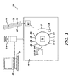
- FIG. 1 illustrates an example of an external drum imaging system 10.
- the imaging system 10 comprises an external drum platesetter configured to record digital data onto a printing plate 18.
- the trailing edge clamping apparatus of the present invention may be used in conjunction with a wide variety of other types of external drum, internal drum, or flatbed imaging systems, including imagesetters and the like.
- the trailing edge clamping apparatus of the present invention may be used to clamp an unexposed printing plate on the plate cylinder of a printing press having an "on-press" imaging system.
- the trailing edge clamping apparatus of the present invention may be used to clamp a sheet-like material to any type of cylindrical drum.
- the imaging system 10 generally includes a front end computer or workstation 12 for the design, layout, editing, and/or processing of digital files representing pages to be printed, a raster image processor (RIP) 14 for processing the digital pages to provide rasterized page data (e.g., rasterized digital files) for driving an image recorder, and an image recorder or engine, such as an external drum platesetter 16, for recording the rasterized digital files onto a printing plate 18.
- rasterized page data e.g., rasterized digital files
- an image recorder or engine such as an external drum platesetter 16 for recording the rasterized digital files onto a printing plate 18.
- a stack 20 of printing plates 18 is commonly supplied in a cassette 22.
- a printing plate 18 is picked off of the stack 20 and subsequently mounted on an external drum 24 of the external drum platesetter 16 by an autoloading system 26.
- a plate manager (not shown) may be used to automatically and selectively unload and feed a printing plate from a plurality of different cassettes to the external drum imaging system for imaging.
- the external drum platesetter 16 includes an external drum 24 having a cylindrical media support surface 28 for supporting a printing plate 18 during imaging.
- the external drum platesetter 16 further includes a scanning system 30, coupled to a movable carriage 32, for recording digital data onto the imaging surface 34 of the printing plate 18 using at least one imaging beam 36.
- FIG. 2 shows an example of a scanning system 30.
- the scanning system 30 is displaced by the movable carriage 32 in a slow scan axial direction (directional arrow A) along the length of the rotating external drum 24 to expose the printing plate 18 in a line-wise manner when a single beam is used or in a section-wise manner for multiple beams.
- Other types of imaging systems may also be used in the present invention.
- the external drum 24 is rotated by a drive system 38 in a clockwise or counterclockwise direction.
- the drive system 38 rotates the external drum 24 at a rate of about 100-1000 rpm.
- the scanning system 30 includes a system 40 for generating the imaging beam or beams 36.
- the system 40 comprises a light or radiation source 42 for producing the imaging beam or beams 36 (illustrated for simplicity as a single beam), and an optical system 44 positioned between the radiation source 42 and the media support surface 28 for focusing the imaging beam or beams 36 onto the printing plate 18. It should be noted, however, that the system 40 described above is only one of many possible different types of scanning systems that may be used to record image data on the printing plate 18.
- FIG. 1 shows in the external drum imaging system 10, the leading edge 46 of the printing plate 18 is held in position against the media support surface 28 of the external drum 24 by a leading edge clamping mechanism 48. Similarly, the trailing edge 50 of the printing plate 18 is held in position against the media support surface 28 of the external drum 24 by a trailing edge clamping mechanism 52.
- a leading edge clamping mechanism 48 is detailed in U.S. Patent No. 6,412,413. Many other known systems may also be used to clamp the leading edge 46 of the printing plate 18 against the media support surface 28 of the external drum 24.
- leading edge clamping mechanism 48 and the trailing edge clamping mechanism 52 provide a tangential friction force between the printing plate 18 and the media support surface 28 of the external drum 24 that is sufficient to resist the tendency of the edges of the printing plate 18 to pull out of the clamping mechanisms 48, 52, at a high drum rotational speed.
- a vacuum source 54 may be used to draw a vacuum through an arrangement of ports and vacuum grooves 56 (FIG. 2) to hold the printing plate 18 against the media support surface 28 of the external drum 24.
- the vacuum source 54 may also supply a vacuum to the autoloading system 26 that is configured to remove or "pick" the top printing plate 18 from the stack 20 of printing plates.
- a registration system comprising, for example, a set of registration pins on the external drum 24, and a plate edge detection system (not shown), may be used to accurately and repeatably position and locate each printing plate 18 on the external drum 24.
- FIGS. 3-8 illustrate an embodiment of a trailing edge clamping mechanism 100 in accordance with the present invention. As shown in FIG.
- the trailing edge clamping mechanism 100 includes a plurality of magnetic clamp sections 102 which collectively extend axially across a substantial portion of the width of the external drum 24.
- the length of the trailing edge clamping mechanism 100 is generally greater than the width of the largest printing plate 18 that may be imaged on the external drum 24.
- the magnetic clamp sections 102 of the trailing edge clamping mechanism 100 may be collectively or individually positioned against, and removed from, the media support surface 28 of the external drum 24 by an actuating system (not shown) comprising at least one actuator.
- the external drum 24 is formed of a material such as steel or a ferromagnetic alloy.
- Each magnetic clamp section 102 includes one or more magnets (FIGS. 6, 8) for securing the section 102 on the external drum 24.
- FIGS. 4-8 show for example, a plurality of the magnetic clamp sections 102 are shown positioned on the external drum 24 over the trailing edge 50 of the printing plate 18.
- the magnetic attraction of the plurality of the magnetic clamp sections 102 is sufficient to hold the trailing edge 50 of the printing plate 18 in position on the media support surface 28 of the external drum 24 during imaging.
- the structure of a magnetic clamp section 102 is shown in greater detail in FIGS. 4-8.
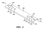
- the magnetic clamp section 102 includes a body 104 having a top portion 106 and a pair of legs 108.
- the bottom surfaces 110 of the legs 108 form the clamping surfaces of the magnetic clamp section 102.
- the magnetic clamp section 102 may be formed from steel or any other suitable material.
- the magnetic clamp section 102 can be formed of a single piece of cold rolled 1018-1020 14 GA. (0.075" thick) steel.
- a plurality of apertures 112 are formed in the top portion 106 of the body 104. Each aperture 112 includes a circular area 114 and an oval area 116. As shown in FIG.
- the lift pads 200 of an actuating system are removably inserted into the apertures 112 to position the magnetic clamp section 102 against, and to remove the magnetic clamp section 102 from, the media support surface 28 of the external drum 24.
- the lift pads 200 are designed to be inserted/removed through the circular area 114 of each aperture 112 as indicated by directional arrows 202, and are designed to be displaced sideways into/out of the oval areas 116 to engage/disengage the magnetic clamp section 102 as indicated by directional arrows 204.
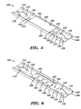
- at least one permanent magnet 120 is positioned within a recess 122 formed in the underside 124 of the top portion 106 of the body 104.
- Each magnet 120 is secured within the recess 122 using an adhesive or other suitable method.
- the type/number of magnets 120 that are used is application specific, and must be chosen such that the clamping force provided by the plurality of the magnetic clamp sections 102 forming the trailing edge clamping mechanism 100 is sufficient to prevent a printing plate from lifting off of the drum during rotation and imaging.
- the magnetic force provided by each clamp section 102 may be in the range of about 19 to 30 lbs.
- four permanent neodymium-iron-boron (Nd-Fe-B) magnets 120 are used.
- a cover 126 is provided to encapsulate and protect the magnets 120 from damage during the operation of the trailing edge clamping mechanism 100.
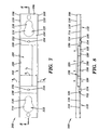
- the cover 126 includes a raised portion 128 for accommodating the magnets 120, and a pair of opposing flanges 130 for securing the cover 126 to the underside 124 of the top portion 106 of the body 104. As shown in FIG. 8, the raised portion 128 of the cover 126 does not extend beyond the bottom surfaces 110 of the legs 108 that form the clamping surfaces of the magnetic clamp section 102. As such, the cover 126 does not interfere with the clamping function of the legs 108. In the disclosed embodiment of the present invention, 0.015" stainless steel is used to form the cover 126. Other materials capable of covering and protecting the magnets 120 may also be used to form the cover. As can be seen in FIGS. 5, 7, and 8, the magnets 120 are completely enclosed by the cover 126.
- width W c of the cover 126 is chosen to be substantially equal to the distance D L between the legs 108 of body 104, and the length L c of the raised portion 128 of the cover 126 is chosen to be at least as long as the configuration of magnets 120.
- the cover 126 is attached to the underside 124 of the top portion 106 of the body 104 using the pair of opposing flanges 130.
- an opening 132 is formed in each flange 130 and rivets 134 are used to secure the cover to the underside 124 of the top portion 106 of the body 104 via the openings 132.
- Each rivet 134 extends through a flange opening 132 and a corresponding opening 136 formed in the top portion 106 of the body 104.
- Other known attachment techniques/hardware may also be used to attach the cover 126 to the underside 124 of the top portion 106 of the body 104.
Landscapes
- Engineering & Computer Science (AREA)
- Mechanical Engineering (AREA)
- Manufacturing & Machinery (AREA)
- Exposure And Positioning Against Photoresist Photosensitive Materials (AREA)
Abstract
An apparatus for clamping the trailing edge (100) of a supply of
recording media on the external drum (6) of an imaging system (10).
The trailing edge clamping apparatus (100) includes a plurality of
magnetic clamp sections (102). Each magnetic clamp section (102)
includes: a body (104) having a top portion (106) and a pair of
legs (108); a plurality of apertures (112); a set of permanent
magnets (120); and a cover for encapsulating and protecting the set
of permanent magnets (120).
Description
- The present invention relates to a trailing edge clamping mechanism for securing a trailing end of a printing plate on an external drum. More specifically the invention is related to an imaging system.
- In external drum imaging systems, a movable optical carriage is commonly used to displace an image recording source in a slow scan direction while a cylindrical drum, having recording media mounted on an external surface thereof, is rotated with respect to the image recording source. The drum rotation causes the recording media to advance past the image recording source along a fast scan direction that is substantially perpendicular to the slow scan direction.
- The image recording source may include an optical system for generating at least one imaging beam that is scanned across the surface of the recording media. Each imaging beam may be separately modulated according to a digital information signal representing data corresponding to the image to be recorded.
- The recording media to be imaged by an external drum imaging system is commonly supplied in discrete, flexible sheets, hereinafter collectively referred to as "printing plates." Each printing plate may comprise one or more layers supported by a support substrate, which for many printing plates is a plano-graphic aluminum sheet. Other layers may include one or more image recording (i.e., "imageable") layers such as a photosensitive, radiation sensitive, or thermally sensitive layer, or other chemically or physically alterable layers. Printing plates that are supported by a polyester support substrate are also known and can be used in the present invention. Printing plates are available in a wide variety of sizes, typically ranging, e.g., from 229 mm x 305 mm (9" x 12"), or smaller, to 1473 mm x 2032 mm (58" x 80"), or larger.
- A cassette is often used to supply a plurality of unexposed printing plates to an external drum imaging system. The printing plates are normally supplied in stacks of ten to one hundred, depending upon plate thickness, and are stored in the cassette. A plate manager may be used to automatically and selectively unload and feed a printing plate from a plurality of different cassettes to the external drum imaging system for imaging.
- Many clamping systems are available for holding the trailing edge of a printing plate on the external drum of an external drum imaging system. One commonly used type of clamping system, for example, employs a plurality of magnets to hold the trailing edge of a printing plate in place. An example of a magnetic trailing edge clamping mechanism is disclosed in U.S. Patent No. 6,412,413. Although this type of trailing edge clamping mechanism is effective, it has several drawbacks. For instance, a magnet of the trailing edge clamping mechanism may break apart from impact loads during normal operational conditions. If this should occur, small pieces of the magnet may adhere to the surface of the external drum. Since this may adversely affect the quality of the imaging provided by the imaging system, the external drum must be carefully cleaned to ensure that all pieces of the broken magnet have been removed. The trailing edge clamping system must also be repaired. This requires that the external drum imaging system be shut down and serviced by a technician, which reduces the throughput of the imaging system (e.g., the number of plates/hour that can be imaged by the system).
- The above-mentioned problems are solved by a mechanism having the specific features set out in claim 1 and a imaging system according to claim 9. Specific features for preferred embodiments of the invention are set out in the dependent claims.
- The present invention provides an apparatus and method for clamping the trailing edge of a printing plate on the external drum of an imaging system.
- Generally, the present invention provides a trailing edge clamping mechanism for securing a trailing end of a printing plate on an external drum of an imaging system, comprising: a plurality of magnetic clamp sections, wherein each magnetic clamp section includes: a body having a top portion and a pair of legs, wherein a bottom surface of each leg forms a clamping surface of the magnetic clamp section; a plurality of apertures formed in the top portion of the body for receiving a corresponding plurality of lift pads of an actuating system; a set of permanent magnets mounted to an underside of the top portion of the body; and a cover for encapsulating and protecting the set of permanent magnets, wherein the cover includes a raised portion for accommodating the set of permanent magnets, and a pair of flanges for securing the cover to the underside of the top portion of the body.
- The present invention further provides an imaging system comprising: an external drum for supporting a printing plate; a system for recording image data onto the printing plate; a leading edge clamping apparatus for clamping a leading edge of the printing plate on the external drum; and a trailing edge clamping apparatus for clamping a trailing edge of the printing plate on the external drum, wherein the trailing edge clamping apparatus includes a plurality of magnetic clamp sections, and wherein each magnetic clamp section includes: a body having a top portion and a pair of legs, wherein a bottom surface of each leg forms a clamping surface of the magnetic clamp section; a plurality of apertures formed in the top portion of the body for receiving a corresponding plurality of lift pads of an actuating system; a set of permanent magnets mounted to an underside of the top portion of the body; and a cover for encapsulating and protecting the set of permanent magnets, wherein the cover includes a raised portion for accommodating the set of permanent magnets, and a pair of flanges for securing the cover to the underside of the top portion of the body.
- Further advantages and embodiments of the present invention will become apparent from the following description and drawings.
- The features of the present invention will best be understood from a detailed description of the invention and embodiments thereof selected for the purpose of illustration and shown in the accompanying drawings in which:
- FIG. 1 illustrates an external drum imaging system for recording images onto a printing plate.
- FIG. 2 illustrates an example of an imaging system including a movable optical carriage and scanning system, usable in the external drum imaging system of FIG. 1.
- FIG. 3 is a perspective view of an external drum including a trailing edge clamping mechanism in accordance with an embodiment of the present invention.
- FIG. 4 is a top perspective view of one section of the trailing edge clamping mechanism of FIG. 3.
- FIG. 5 is a bottom perspective view of one section of the trailing edge clamping mechanism.
- FIG. 6 illustrates an arrangement of magnets used in the trailing edge clamping mechanism.
- FIG. 7 is bottom plan view of one section of the trailing edge clamping mechanism.
- FIG. 8 is a cross-sectional view of one section of the trailing edge clamping mechanism taken along line 8-8 of FIG. 7.
- FIG. 9 illustrates the operation of the lift pads of an actuating system.
-
- The features of the present invention are illustrated in detail in the accompanying drawings, wherein like reference numerals refer to like elements throughout the drawings. Although the drawings are intended to illustrate the present invention, the drawings are not necessarily drawn to scale.
- FIG. 1 illustrates an example of an external
drum imaging system 10. In this example, theimaging system 10 comprises an external drum platesetter configured to record digital data onto aprinting plate 18. Although described below with regard to an external drum platesetter, the trailing edge clamping apparatus of the present invention may be used in conjunction with a wide variety of other types of external drum, internal drum, or flatbed imaging systems, including imagesetters and the like. Further, the trailing edge clamping apparatus of the present invention may be used to clamp an unexposed printing plate on the plate cylinder of a printing press having an "on-press" imaging system. In its broadest sense, the trailing edge clamping apparatus of the present invention may be used to clamp a sheet-like material to any type of cylindrical drum. - The
imaging system 10 generally includes a front end computer orworkstation 12 for the design, layout, editing, and/or processing of digital files representing pages to be printed, a raster image processor (RIP) 14 for processing the digital pages to provide rasterized page data (e.g., rasterized digital files) for driving an image recorder, and an image recorder or engine, such as anexternal drum platesetter 16, for recording the rasterized digital files onto aprinting plate 18.
Astack 20 ofprinting plates 18 is commonly supplied in acassette 22. Aprinting plate 18 is picked off of thestack 20 and subsequently mounted on anexternal drum 24 of theexternal drum platesetter 16 by anautoloading system 26. A plate manager (not shown) may be used to automatically and selectively unload and feed a printing plate from a plurality of different cassettes to the external drum imaging system for imaging.
Theexternal drum platesetter 16 includes anexternal drum 24 having a cylindricalmedia support surface 28 for supporting aprinting plate 18 during imaging. Theexternal drum platesetter 16 further includes ascanning system 30, coupled to amovable carriage 32, for recording digital data onto theimaging surface 34 of theprinting plate 18 using at least oneimaging beam 36. FIG. 2 shows an example of ascanning system 30. In particular, thescanning system 30 is displaced by themovable carriage 32 in a slow scan axial direction (directional arrow A) along the length of the rotatingexternal drum 24 to expose theprinting plate 18 in a line-wise manner when a single beam is used or in a section-wise manner for multiple beams. Other types of imaging systems may also be used in the present invention. - As indicated by directional arrow B in FIG. 1 the
external drum 24 is rotated by adrive system 38 in a clockwise or counterclockwise direction. Typically, thedrive system 38 rotates theexternal drum 24 at a rate of about 100-1000 rpm. As illustrated in FIG. 2, thescanning system 30 includes asystem 40 for generating the imaging beam orbeams 36. Thesystem 40 comprises a light orradiation source 42 for producing the imaging beam or beams 36 (illustrated for simplicity as a single beam), and anoptical system 44 positioned between theradiation source 42 and themedia support surface 28 for focusing the imaging beam orbeams 36 onto theprinting plate 18. It should be noted, however, that thesystem 40 described above is only one of many possible different types of scanning systems that may be used to record image data on theprinting plate 18. - FIG. 1 shows in the external
drum imaging system 10, the leadingedge 46 of theprinting plate 18 is held in position against themedia support surface 28 of theexternal drum 24 by a leadingedge clamping mechanism 48. Similarly, the trailingedge 50 of theprinting plate 18 is held in position against themedia support surface 28 of theexternal drum 24 by a trailingedge clamping mechanism 52. An example of a suitable leadingedge clamping mechanism 48 is detailed in U.S. Patent No. 6,412,413. Many other known systems may also be used to clamp theleading edge 46 of theprinting plate 18 against themedia support surface 28 of theexternal drum 24. The leadingedge clamping mechanism 48 and the trailingedge clamping mechanism 52 provide a tangential friction force between theprinting plate 18 and themedia support surface 28 of theexternal drum 24 that is sufficient to resist the tendency of the edges of theprinting plate 18 to pull out of the clampingmechanisms - A
vacuum source 54 may be used to draw a vacuum through an arrangement of ports and vacuum grooves 56 (FIG. 2) to hold theprinting plate 18 against themedia support surface 28 of theexternal drum 24. Thevacuum source 54 may also supply a vacuum to the autoloadingsystem 26 that is configured to remove or "pick" thetop printing plate 18 from thestack 20 of printing plates. A registration system comprising, for example, a set of registration pins on theexternal drum 24, and a plate edge detection system (not shown), may be used to accurately and repeatably position and locate eachprinting plate 18 on theexternal drum 24.
FIGS. 3-8 illustrate an embodiment of a trailingedge clamping mechanism 100 in accordance with the present invention.
As shown in FIG. 3, the trailingedge clamping mechanism 100 includes a plurality ofmagnetic clamp sections 102 which collectively extend axially across a substantial portion of the width of theexternal drum 24. The length of the trailingedge clamping mechanism 100 is generally greater than the width of thelargest printing plate 18 that may be imaged on theexternal drum 24. Themagnetic clamp sections 102 of the trailingedge clamping mechanism 100 may be collectively or individually positioned against, and removed from, themedia support surface 28 of theexternal drum 24 by an actuating system (not shown) comprising at least one actuator.
Theexternal drum 24 is formed of a material such as steel or a ferromagnetic alloy. Eachmagnetic clamp section 102 includes one or more magnets (FIGS. 6, 8) for securing thesection 102 on theexternal drum 24. FIG. 3 shows for example, a plurality of themagnetic clamp sections 102 are shown positioned on theexternal drum 24 over the trailingedge 50 of theprinting plate 18. The magnetic attraction of the plurality of themagnetic clamp sections 102 is sufficient to hold the trailingedge 50 of theprinting plate 18 in position on themedia support surface 28 of theexternal drum 24 during imaging.
The structure of amagnetic clamp section 102 is shown in greater detail in FIGS. 4-8.
As shown in FIGS. 4-8, themagnetic clamp section 102 includes abody 104 having atop portion 106 and a pair oflegs 108. The bottom surfaces 110 of thelegs 108 form the clamping surfaces of themagnetic clamp section 102. Although shown as being flat, thebottom surface 110 of eachleg 108 has been rounded to remove any sharp edges that may potentially damage the surface of a printing plate. Themagnetic clamp section 102 may be formed from steel or any other suitable material. For example, themagnetic clamp section 102 can be formed of a single piece of cold rolled 1018-1020 14 GA. (0.075" thick) steel.
A plurality ofapertures 112 are formed in thetop portion 106 of thebody 104. Eachaperture 112 includes acircular area 114 and anoval area 116. As shown in FIG. 9, thelift pads 200 of an actuating system (not shown) are removably inserted into theapertures 112 to position themagnetic clamp section 102 against, and to remove themagnetic clamp section 102 from, themedia support surface 28 of theexternal drum 24. In particular, thelift pads 200 are designed to be inserted/removed through thecircular area 114 of eachaperture 112 as indicated bydirectional arrows 202, and are designed to be displaced sideways into/out of theoval areas 116 to engage/disengage themagnetic clamp section 102 as indicated bydirectional arrows 204.
As shown in FIGS. 6 and 8, at least onepermanent magnet 120 is positioned within arecess 122 formed in theunderside 124 of thetop portion 106 of thebody 104. Eachmagnet 120 is secured within therecess 122 using an adhesive or other suitable method.
The type/number ofmagnets 120 that are used is application specific, and must be chosen such that the clamping force provided by the plurality of themagnetic clamp sections 102 forming the trailingedge clamping mechanism 100 is sufficient to prevent a printing plate from lifting off of the drum during rotation and imaging. For example, the magnetic force provided by eachclamp section 102 may be in the range of about 19 to 30 lbs. In the disclosed embodiment of the present invention, for example, four permanent neodymium-iron-boron (Nd-Fe-B)magnets 120 are used.
Acover 126 is provided to encapsulate and protect themagnets 120 from damage during the operation of the trailingedge clamping mechanism 100. Thecover 126 includes a raisedportion 128 for accommodating themagnets 120, and a pair of opposingflanges 130 for securing thecover 126 to theunderside 124 of thetop portion 106 of thebody 104. As shown in FIG. 8, the raisedportion 128 of thecover 126 does not extend beyond the bottom surfaces 110 of thelegs 108 that form the clamping surfaces of themagnetic clamp section 102. As such, thecover 126 does not interfere with the clamping function of thelegs 108.
In the disclosed embodiment of the present invention, 0.015" stainless steel is used to form thecover 126. Other materials capable of covering and protecting themagnets 120 may also be used to form the cover.
As can be seen in FIGS. 5, 7, and 8, themagnets 120 are completely enclosed by thecover 126. As shown in FIG. 7 in particular, width Wc of thecover 126 is chosen to be substantially equal to the distance DL between thelegs 108 ofbody 104, and the length Lc of the raisedportion 128 of thecover 126 is chosen to be at least as long as the configuration ofmagnets 120.
Thecover 126 is attached to theunderside 124 of thetop portion 106 of thebody 104 using the pair of opposingflanges 130. In the illustrated embodiment of the present invention, for example, anopening 132 is formed in eachflange 130 andrivets 134 are used to secure the cover to theunderside 124 of thetop portion 106 of thebody 104 via theopenings 132. Eachrivet 134 extends through aflange opening 132 and acorresponding opening 136 formed in thetop portion 106 of thebody 104. Other known attachment techniques/hardware may also be used to attach thecover 126 to theunderside 124 of thetop portion 106 of thebody 104.
The foregoing description of the present invention has been presented for purposes of illustration and description. It is not intended to be exhaustive or to limit the invention to the precise form disclosed, and many modifications and variations are possible in light of the above teaching. Such modifications and variations that may be apparent to a person skilled in the art may be included within the scope of this invention.
Claims (10)
- A trailing edge clamping mechanism (100) for securing the trailing end (46) of a printing plate (18) on an external drum (24) of an imaging system (10), comprising:a plurality of magnetic clamp sections (102), wherein each magnetic clamp section (102) includes:i) a body (104) having a top portion (106) and a pair of legs (108), wherein a bottom surface (110) of each leg (108) forms a clamping surface of the magnetic clamp section;ii) a plurality of apertures (112) formed in the top portion (106) of the body (104) for receiving a corresponding plurality of lift pads (200) of an actuating system;iii) a set of permanent magnets (120) mounted to an underside of the top portion (106) of the body (104); andiv) a cover (126) for encapsulating and protecting the set of permanent magnets (120), wherein the cover includes a raised portion (128) for accommodating the set of permanent magnets, and a pair of flanges (130) for securing the cover (126) to the underside of the top portion (106) of the body (104).
- The trailing edge clamping mechanism according to claim 1, wherein the cover (126) completely covers the set of permanent magnets (120).
- The trailing edge clamping mechanism according to any one of the previous claims, wherein the cover (126) has a width that is substantially equal to the distance between the legs (108) of the body (104).
- The trailing edge clamping mechanism according to any one of the previous claims, wherein the set of permanent magnets (120) are positioned within a recess (122) formed in the underside of the top portion (106) of the body (104).
- The trailing edge clamping mechanism according to any one of the previous claims, wherein the set of permanent magnets (120) comprise neodymium-iron-boron magnets.
- The trailing edge clamping mechanism according to any one of the previous claims, wherein each aperture (112) includes a circular area (114) and an oval area (116).
- The trailing edge clamping mechanism according to claim 6 that is configured in such a way that lift pads (200) of an actuating system can be inserted and removed through the circular area (114) and displaced sideways into and out of the oval areas (116).
- The trailing edge clamping mechanism according to any one of the previous claims, wherein the cover (126) comprises stainless steel.
- An imaging system comprising a trailing edge clamping apparatus according to any one of previous claims; andan external drum (24) for supporting a printing plate;a system (30, 32) for recording image data onto the printing plate (18);a leading edge clamping apparatus (48) for clamping a leading edge of the printing plate on the external drum; and
- The imaging system according to claim 9, wherein the imaging system comprises a platesetter.
Applications Claiming Priority (2)
| Application Number | Priority Date | Filing Date | Title |
|---|---|---|---|
| US10/425,216 US6739257B1 (en) | 2003-04-29 | 2003-04-29 | Media clamping apparatus for an external drum imaging system |
| US425216 | 2003-04-29 |
Publications (1)
| Publication Number | Publication Date |
|---|---|
| EP1473157A1 true EP1473157A1 (en) | 2004-11-03 |
Family
ID=32312944
Family Applications (1)
| Application Number | Title | Priority Date | Filing Date |
|---|---|---|---|
| EP04101601A Withdrawn EP1473157A1 (en) | 2003-04-29 | 2004-04-19 | Media clamping apparatus for an external drum imaging system. |
Country Status (2)
| Country | Link |
|---|---|
| US (1) | US6739257B1 (en) |
| EP (1) | EP1473157A1 (en) |
Families Citing this family (2)
| Publication number | Priority date | Publication date | Assignee | Title |
|---|---|---|---|---|
| US20050120898A1 (en) * | 2003-12-05 | 2005-06-09 | Presstek, Inc. | Magnetic plate retention |
| US8777501B2 (en) | 2011-05-11 | 2014-07-15 | Hewlett-Packard Development Company, L.P. | Media loading devices |
Citations (2)
| Publication number | Priority date | Publication date | Assignee | Title |
|---|---|---|---|---|
| US20020011164A1 (en) * | 2000-02-25 | 2002-01-31 | Tice William W. | Pin registration system for mounting different width printing plates |
| US6412413B1 (en) | 2000-02-25 | 2002-07-02 | Agfa Corporation | Media clamp for external drum imaging system |
Family Cites Families (7)
| Publication number | Priority date | Publication date | Assignee | Title |
|---|---|---|---|---|
| US4138102A (en) * | 1977-03-30 | 1979-02-06 | Xerox Corporation | Automatic document processing device |
| US4852490A (en) | 1988-06-27 | 1989-08-01 | T. D. Wright, Inc. | Magnetic cylinder having rigid support for magnet cover |
| US4890553A (en) | 1989-02-16 | 1990-01-02 | Heath Custom Press, Inc. | Positioning and attachment means for flexible printing plates |
| JP3292427B2 (en) * | 1994-11-25 | 2002-06-17 | 理想科学工業株式会社 | Stencil stencil starter for rotary stencil printing press |
| US6130702A (en) | 1995-07-28 | 2000-10-10 | Creo Products Inc. | Method for reliable loading of unexposed printing plates |
| US6457410B1 (en) | 2000-07-07 | 2002-10-01 | Presstek, Inc. | Method and apparatus for magnetically clamping printing plates |
| US6688227B2 (en) * | 2002-04-01 | 2004-02-10 | Presstek, Inc. | Magnetic plate-retention system and method of securing recording medium to rotatable support |
-
2003
- 2003-04-29 US US10/425,216 patent/US6739257B1/en not_active Expired - Fee Related
-
2004
- 2004-04-19 EP EP04101601A patent/EP1473157A1/en not_active Withdrawn
Patent Citations (2)
| Publication number | Priority date | Publication date | Assignee | Title |
|---|---|---|---|---|
| US20020011164A1 (en) * | 2000-02-25 | 2002-01-31 | Tice William W. | Pin registration system for mounting different width printing plates |
| US6412413B1 (en) | 2000-02-25 | 2002-07-02 | Agfa Corporation | Media clamp for external drum imaging system |
Also Published As
| Publication number | Publication date |
|---|---|
| US6739257B1 (en) | 2004-05-25 |
Similar Documents
| Publication | Publication Date | Title |
|---|---|---|
| US6688591B2 (en) | Apparatus and method for removing slip sheets | |
| JP4101689B2 (en) | Apparatus and method for picking up one printing plate from a stack of printing plates | |
| US5889547A (en) | Registration detection apparatus for imaging systems | |
| US6729234B2 (en) | Actuation system in an imaging system | |
| US6705226B1 (en) | Media clamping apparatus and method for an external drum imaging system | |
| US6739257B1 (en) | Media clamping apparatus for an external drum imaging system | |
| EP1394614B1 (en) | System for registering media in an imaging system. | |
| US6571709B1 (en) | Apparatus and method for picking printing plates of various sizes | |
| US6254091B1 (en) | Variable cross-section vacuum grooves in an imaging system | |
| US6792862B1 (en) | Apparatus for delivering printing plates to an external drum imaging system | |
| EP1327594A1 (en) | Apparatus and Method for Supporting and Feeding Printing Plates in an Imaging System | |
| US6994027B1 (en) | Device and method to prevent movement of a printing plate during clamping | |
| US7262878B2 (en) | System and method for calibrating an imaging system during imaging | |
| US7398732B2 (en) | Method for determining an image area to be exposed on a printing plate | |
| US6779450B1 (en) | Thin-wall drum for external drum imaging system | |
| EP1486816A1 (en) | Method and apparatus for reducing contamination in a grating light valve imaging system. | |
| EP1401187A2 (en) | Method and apparatus for incrementally displacing recording media in an imaging system. | |
| JP2000218594A (en) | Low profile type side punch for image setter of drum incorporated type |
Legal Events
| Date | Code | Title | Description |
|---|---|---|---|
| PUAI | Public reference made under article 153(3) epc to a published international application that has entered the european phase |
Free format text: ORIGINAL CODE: 0009012 |
|
| AK | Designated contracting states |
Kind code of ref document: A1 Designated state(s): AT BE BG CH CY CZ DE DK EE ES FI FR GB GR HU IE IT LI LU MC NL PL PT RO SE SI SK TR |
|
| AX | Request for extension of the european patent |
Extension state: AL HR LT LV MK |
|
| 17P | Request for examination filed |
Effective date: 20050503 |
|
| AKX | Designation fees paid |
Designated state(s): DE FR GB |
|
| STAA | Information on the status of an ep patent application or granted ep patent |
Free format text: STATUS: THE APPLICATION IS DEEMED TO BE WITHDRAWN |
|
| 18D | Application deemed to be withdrawn |
Effective date: 20101101 |