EP1471677A1 - Method of blindly detecting a transport format of an incident convolutional encoded signal, and corresponding convolutional code decoder - Google Patents
Method of blindly detecting a transport format of an incident convolutional encoded signal, and corresponding convolutional code decoder Download PDFInfo
- Publication number
- EP1471677A1 EP1471677A1 EP20030290993 EP03290993A EP1471677A1 EP 1471677 A1 EP1471677 A1 EP 1471677A1 EP 20030290993 EP20030290993 EP 20030290993 EP 03290993 A EP03290993 A EP 03290993A EP 1471677 A1 EP1471677 A1 EP 1471677A1
- Authority
- EP
- European Patent Office
- Prior art keywords
- fact
- decoding
- window
- convolutional code
- transport format
- Prior art date
- Legal status (The legal status is an assumption and is not a legal conclusion. Google has not performed a legal analysis and makes no representation as to the accuracy of the status listed.)
- Withdrawn
Links
- 238000000034 method Methods 0.000 title claims abstract description 19
- 238000004422 calculation algorithm Methods 0.000 claims abstract description 33
- 125000004122 cyclic group Chemical group 0.000 claims abstract description 10
- 230000015654 memory Effects 0.000 claims description 49
- 238000004364 calculation method Methods 0.000 claims description 46
- 238000012545 processing Methods 0.000 claims description 44
- 238000001514 detection method Methods 0.000 claims description 13
- 101000870345 Vasconcellea cundinamarcensis Cysteine proteinase 1 Proteins 0.000 claims description 5
- 238000004891 communication Methods 0.000 claims description 5
- 230000001413 cellular effect Effects 0.000 claims description 3
- 230000009897 systematic effect Effects 0.000 description 17
- 230000007704 transition Effects 0.000 description 10
- 238000007792 addition Methods 0.000 description 6
- 101000969594 Homo sapiens Modulator of apoptosis 1 Proteins 0.000 description 5
- 102100021440 Modulator of apoptosis 1 Human genes 0.000 description 5
- 230000009466 transformation Effects 0.000 description 5
- 101100224522 Mus musculus Dppa3 gene Proteins 0.000 description 4
- 101100329418 Saccharomyces cerevisiae (strain ATCC 204508 / S288c) CRG1 gene Proteins 0.000 description 4
- 238000013459 approach Methods 0.000 description 4
- 230000008569 process Effects 0.000 description 4
- 102100025248 C-X-C motif chemokine 10 Human genes 0.000 description 2
- 206010009944 Colon cancer Diseases 0.000 description 2
- 101000979001 Homo sapiens Methionine aminopeptidase 2 Proteins 0.000 description 2
- 101000969087 Homo sapiens Microtubule-associated protein 2 Proteins 0.000 description 2
- 102100021118 Microtubule-associated protein 2 Human genes 0.000 description 2
- 101100222378 Mus musculus Cxcl10 gene Proteins 0.000 description 2
- 230000005540 biological transmission Effects 0.000 description 2
- 239000000470 constituent Substances 0.000 description 2
- 230000006870 function Effects 0.000 description 2
- 238000011835 investigation Methods 0.000 description 2
- 238000000844 transformation Methods 0.000 description 2
- 238000007476 Maximum Likelihood Methods 0.000 description 1
- 230000003213 activating effect Effects 0.000 description 1
- 230000001174 ascending effect Effects 0.000 description 1
- 230000006399 behavior Effects 0.000 description 1
- 230000015556 catabolic process Effects 0.000 description 1
- 238000002485 combustion reaction Methods 0.000 description 1
- 230000000295 complement effect Effects 0.000 description 1
- 238000007796 conventional method Methods 0.000 description 1
- 238000012937 correction Methods 0.000 description 1
- 238000006731 degradation reaction Methods 0.000 description 1
- 230000000593 degrading effect Effects 0.000 description 1
- 238000010586 diagram Methods 0.000 description 1
- 238000011156 evaluation Methods 0.000 description 1
- 230000006872 improvement Effects 0.000 description 1
- 238000013507 mapping Methods 0.000 description 1
- 230000008450 motivation Effects 0.000 description 1
- 238000004088 simulation Methods 0.000 description 1
- 238000012546 transfer Methods 0.000 description 1
Images









Classifications
-
- H—ELECTRICITY
- H03—ELECTRONIC CIRCUITRY
- H03M—CODING; DECODING; CODE CONVERSION IN GENERAL
- H03M13/00—Coding, decoding or code conversion, for error detection or error correction; Coding theory basic assumptions; Coding bounds; Error probability evaluation methods; Channel models; Simulation or testing of codes
- H03M13/37—Decoding methods or techniques, not specific to the particular type of coding provided for in groups H03M13/03 - H03M13/35
- H03M13/39—Sequence estimation, i.e. using statistical methods for the reconstruction of the original codes
- H03M13/3905—Maximum a posteriori probability [MAP] decoding or approximations thereof based on trellis or lattice decoding, e.g. forward-backward algorithm, log-MAP decoding, max-log-MAP decoding
-
- H—ELECTRICITY
- H03—ELECTRONIC CIRCUITRY
- H03M—CODING; DECODING; CODE CONVERSION IN GENERAL
- H03M13/00—Coding, decoding or code conversion, for error detection or error correction; Coding theory basic assumptions; Coding bounds; Error probability evaluation methods; Channel models; Simulation or testing of codes
- H03M13/29—Coding, decoding or code conversion, for error detection or error correction; Coding theory basic assumptions; Coding bounds; Error probability evaluation methods; Channel models; Simulation or testing of codes combining two or more codes or code structures, e.g. product codes, generalised product codes, concatenated codes, inner and outer codes
- H03M13/2957—Turbo codes and decoding
-
- H—ELECTRICITY
- H03—ELECTRONIC CIRCUITRY
- H03M—CODING; DECODING; CODE CONVERSION IN GENERAL
- H03M13/00—Coding, decoding or code conversion, for error detection or error correction; Coding theory basic assumptions; Coding bounds; Error probability evaluation methods; Channel models; Simulation or testing of codes
- H03M13/37—Decoding methods or techniques, not specific to the particular type of coding provided for in groups H03M13/03 - H03M13/35
- H03M13/3738—Decoding methods or techniques, not specific to the particular type of coding provided for in groups H03M13/03 - H03M13/35 with judging correct decoding
-
- H—ELECTRICITY
- H03—ELECTRONIC CIRCUITRY
- H03M—CODING; DECODING; CODE CONVERSION IN GENERAL
- H03M13/00—Coding, decoding or code conversion, for error detection or error correction; Coding theory basic assumptions; Coding bounds; Error probability evaluation methods; Channel models; Simulation or testing of codes
- H03M13/37—Decoding methods or techniques, not specific to the particular type of coding provided for in groups H03M13/03 - H03M13/35
- H03M13/39—Sequence estimation, i.e. using statistical methods for the reconstruction of the original codes
- H03M13/3905—Maximum a posteriori probability [MAP] decoding or approximations thereof based on trellis or lattice decoding, e.g. forward-backward algorithm, log-MAP decoding, max-log-MAP decoding
- H03M13/3922—Add-Compare-Select [ACS] operation in forward or backward recursions
-
- H—ELECTRICITY
- H03—ELECTRONIC CIRCUITRY
- H03M—CODING; DECODING; CODE CONVERSION IN GENERAL
- H03M13/00—Coding, decoding or code conversion, for error detection or error correction; Coding theory basic assumptions; Coding bounds; Error probability evaluation methods; Channel models; Simulation or testing of codes
- H03M13/37—Decoding methods or techniques, not specific to the particular type of coding provided for in groups H03M13/03 - H03M13/35
- H03M13/39—Sequence estimation, i.e. using statistical methods for the reconstruction of the original codes
- H03M13/3905—Maximum a posteriori probability [MAP] decoding or approximations thereof based on trellis or lattice decoding, e.g. forward-backward algorithm, log-MAP decoding, max-log-MAP decoding
- H03M13/3927—Log-Likelihood Ratio [LLR] computation by combination of forward and backward metrics into LLRs
-
- H—ELECTRICITY
- H03—ELECTRONIC CIRCUITRY
- H03M—CODING; DECODING; CODE CONVERSION IN GENERAL
- H03M13/00—Coding, decoding or code conversion, for error detection or error correction; Coding theory basic assumptions; Coding bounds; Error probability evaluation methods; Channel models; Simulation or testing of codes
- H03M13/37—Decoding methods or techniques, not specific to the particular type of coding provided for in groups H03M13/03 - H03M13/35
- H03M13/39—Sequence estimation, i.e. using statistical methods for the reconstruction of the original codes
- H03M13/41—Sequence estimation, i.e. using statistical methods for the reconstruction of the original codes using the Viterbi algorithm or Viterbi processors
- H03M13/4107—Sequence estimation, i.e. using statistical methods for the reconstruction of the original codes using the Viterbi algorithm or Viterbi processors implementing add, compare, select [ACS] operations
-
- H—ELECTRICITY
- H04—ELECTRIC COMMUNICATION TECHNIQUE
- H04L—TRANSMISSION OF DIGITAL INFORMATION, e.g. TELEGRAPHIC COMMUNICATION
- H04L1/00—Arrangements for detecting or preventing errors in the information received
- H04L1/004—Arrangements for detecting or preventing errors in the information received by using forward error control
- H04L1/0045—Arrangements at the receiver end
- H04L1/0046—Code rate detection or code type detection
-
- H—ELECTRICITY
- H04—ELECTRIC COMMUNICATION TECHNIQUE
- H04L—TRANSMISSION OF DIGITAL INFORMATION, e.g. TELEGRAPHIC COMMUNICATION
- H04L1/00—Arrangements for detecting or preventing errors in the information received
- H04L1/004—Arrangements for detecting or preventing errors in the information received by using forward error control
- H04L1/0045—Arrangements at the receiver end
- H04L1/0055—MAP-decoding
-
- H—ELECTRICITY
- H04—ELECTRIC COMMUNICATION TECHNIQUE
- H04L—TRANSMISSION OF DIGITAL INFORMATION, e.g. TELEGRAPHIC COMMUNICATION
- H04L1/00—Arrangements for detecting or preventing errors in the information received
- H04L1/004—Arrangements for detecting or preventing errors in the information received by using forward error control
- H04L1/0056—Systems characterized by the type of code used
- H04L1/0059—Convolutional codes
-
- H—ELECTRICITY
- H04—ELECTRIC COMMUNICATION TECHNIQUE
- H04L—TRANSMISSION OF DIGITAL INFORMATION, e.g. TELEGRAPHIC COMMUNICATION
- H04L1/00—Arrangements for detecting or preventing errors in the information received
- H04L1/004—Arrangements for detecting or preventing errors in the information received by using forward error control
- H04L1/0056—Systems characterized by the type of code used
- H04L1/0061—Error detection codes
-
- H—ELECTRICITY
- H04—ELECTRIC COMMUNICATION TECHNIQUE
- H04L—TRANSMISSION OF DIGITAL INFORMATION, e.g. TELEGRAPHIC COMMUNICATION
- H04L1/00—Arrangements for detecting or preventing errors in the information received
- H04L1/004—Arrangements for detecting or preventing errors in the information received by using forward error control
- H04L1/0056—Systems characterized by the type of code used
- H04L1/0064—Concatenated codes
- H04L1/0066—Parallel concatenated codes
Definitions
- the invention relates in general to channel coding and decoding techniques, especially convolutional codes, and more particularly to the blind transport format detection (BTFD).
- BTFD blind transport format detection
- An application of the invention is directed in general to the field of wireless communication systems, and more particularly to the CDMA systems such as the different CDMA based mobile radio systems like CDMA 2000, WCDMA (Wide Band CDMA) or the IS-95 standard.
- CDMA Code Division Multiple Access 2000
- WCDMA Wide Band CDMA
- the third generation mobile radio system specifies Convolutional codes as well as Turbo-codes as channel coding techniques [3GPP, Technical Specification Group Radio Access Network ; Multiplexing and channel coding (FDD) ; (3G TS 25.212 version 3.5.0(2000-12)), Release 1999].
- the UMTS standard defines, beside the TFCI (Transport Format Combination Indicator) base transport format detection, a possibility of blindly detect the transport format in use. More details can be found in 3GPP, Technical Specification Group Radio Access Network; Multiplexing and channel coding (FDD); (3G TS 25.212 version 4.3.0 (2001-12)), Release 4.
- TFCI Transport Format Combination Indicator
- This option is used in order to reduce the TFCI symbol overhead in the transmission frame and thus to increase the air load.
- the explicitly blind detected transport channels have to be coded using a convolutional code.
- the blind transport format detection is based in the use of the CRC (Cyclic Redundancy Check) words.
- CRC Cyclic Redundancy Check
- An example of such detection can be found in the annex of the above mentioned 3GPP document.
- the main idea is to use a Viterbi decoder for decoding the different possible block sizes corresponding to the possible transport formats which can be used in the transport channel under investigation.
- a CRC word Cyclic Redundancy Check word
- a correct CRC determines the correct block size. For large CRC length, the CRC check is sufficient to determine the correct block.
- the invention intends to provide a solution to this problem and proposes a different method of blindly detecting a transport format of an incident convolutional encoded signal.
- said transport format being ex ante unknown and belonging to a set of MF predetermined reference transport formats
- said signal comprising a data block having an ex ante unknown number of bits corresponding to said ex ante unknown transport format, and a Cyclic Redundancy Check (CRC) field, containing a transmitted CRC word
- the method according to the invention comprises decoding said signal using a Maximum-a-Posteriori algorithm, said decoding step including decoding said signal considering respectively the MF possible reference formats and respectively delivering MF corresponding groups of soft output information, calculating from each group of soft output information a calculated CRC word and comparing said calculated CRC word with said transmitted CRC word, selecting all the groups for which said calculated CRC word is equal to said transmitted CRC word, and selecting the actual transport format of the encoded signal from at least one soft output information among the last ones of each selected group.
- CRC Cyclic Redundancy Check
- the invention uses already calculated soft output information (LLR information) as additional metric to distinguish between two or more blocks with a correct CRC.
- LLR information soft output information
- the actual transport format of the encoded signal is selected from the last soft output information of each selected group.
- the actual transport format is for example the reference format having the greatest last soft output information.
- said decoding step comprises calculating state metrics, and all the data blocks are decoded in parallel window-by-window on sliding windows having a predetermined size, and at least some of the states metrics calculated on a window are valid for all the data blocks.
- said decoding step comprises for each window calculating forward state metrics during a forward recursion, performing a backward acquisition having a predetermined acquisition length, calculating backward state metrics during a backward recursion and calculating soft output information in the reverse order, and for each window only one forward recursion is performed which is valid for all the transport formats.
- the first window processing including forward recursion, backward acquisition, backward recursion and soft output calculation, is completely valid for all data blocks having a size larger than the sum of the window size and the acquisition length.
- the invention proposes also a convolutional code decoder, comprising
- said second selection means are adapted to select the actual transport format of the encoded signal from the last soft output information of each selected group.
- said convolutional code decoding means are adapted to calculate state metrics, all the data blocks are decoded in parallel window-by-window on sliding windows having a predetermined size, and at least some of the state metrics calculated on a window are valid for all the data blocks.
- said convolutional code decoding means are adapted for each window, to calculate forward state metrics during a forward recursion, to perform a backward acquisition having a predetermined acquisition length, to calculate backward state metrics during a backward recursion, and for each window only one forward recursion is performed which is valid for all the transport formats.
- the first window processing including forward recursion, backward acquisition, backward recursion and soft output calculation, is completely valid for all data blocks having a size larger than the sum of the window size and the acquisition length.
- the code decoder according to the invention can be a combined Turbo-code/convolutional code decoder further comprising Turbo-code decoding means for performing Turbo-code decoding.
- said Turbo-code and convolutional code decoding means comprises common processing means having a first configuration dedicated to Turbo-code decoding and a second configuration dedicated to convolutional code decoding.
- said decoder further comprises :
- Said common processing means may implement a Maximum-A posteriori (MAP) algorithm.
- MAP Maximum-A posteriori
- the MAP algorithm implemented is for example a so-called LogMAP algorithm or a so-called MaxLogMAP algorithm.
- the convolutional code decoder according to the invention may be advantageously realized by an integrated circuit.
- the invention proposes also a terminal of a wireless communication system including a decoder as defined above.
- This terminal may form a cellular phone or a base station.
- Convolutional encoding is performed by calculating the modulo-2 sum of the input values of the current and/or selected previous time steps. Implementation therefore is straightforward and mainly consists of shift register and a couple of exclusive-OR gates. Through the way those are switched, different kinds of convolutional codes can be realized:
- An instance of a convolutional encoder is defined by a combination of these properties, the memory depth (constraint length) and the logical functions used to produce the parity information. These properties are described through generator polynomials.
- Figure 1 represents the structure of two different NSC used in UMTS for Convolution and Convolutional encoding. Furthermore, two different rates have to be considered.
- the rate 1/2 convolutional encoder (a) has two outputs, whereas the rate 1/3 encoder (b) has three outputs.
- M K-1 flip-flops are needed to store the encoder history. This gives rise to an interpretation of the encoder as finite-state machine (FSM). It shows a behavior equivalent to a Mealy-automaton. The likelihood of a transition between two states is the key to the decoding of convolutional codes.
- FSM finite-state machine
- a code trellis is the unrolled state chart of a finite-state machine.
- a trellis is used to depict those transitions.
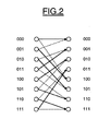
- a part of a trellis is shown, that represents the possible transitions in one time-step.
- the trellis combines states which are equivalent. Solid lines in figure 2 stand for transitions due to the input of a systematic bit of "0" whereas dashed lines represent those caused by a "1".
- the initial state of the trellis is always known to be the all-zero state.
- the encoder ends in an arbitrary state, leaving no hint where to start the backward recursion. This can be counteracted by driving the encoder into a defined final state. Reaching the final state (e.g. the all-zero state) can be achieved by appending a sequence, which steers the encoder towards the final state as fast as possible. This sequence is also depending on the state the encoder is in after the last information bit has been coded. The length of this sequence is equal to K-1; the transmitted bits are called tailbits.
- probabilities can be computed that certain combinations of systematic and parity bit occurred. From this and considering the encoder history, the probability that the encoder was in a given state at a given time-step can be computed.
- Viterbi Decoder is a sequence estimator.
- the maximum- ⁇ -posteriori (MAP) algorithm estimates the probability that the encoder was in the given state and that the current state leads to the final state given the remainder of the channel values. This can be efficient computed by a forward and backward recursion over the trellis. Afterwards, for each bit the probabilities for those states associated with a systematic "0" are added and compared to those associated with a "1". The symbol with the higher probability is assumed to be the sent one. As this works on bit rather than on sequence level, it is called symbol estimation.
- Equation 2.1 shows the output of such a MAP decoder.
- APP a-posteriori probabilities
- the a-posteriori probability itself can be expressed as
- the MAP algorithm has to be transformed to the logarithmic domain, where it becomes the LogMAP algorithm, which increases numerical stability and eases implementation, while not degrading the error correction performance.
- min* ( ⁇ 1, ⁇ 2) min( ⁇ 1, ⁇ 2) - ln(1 + e -
- the max* is applied recursively. Since the operator is associative, a tree-like evaluation can be employed, which is advantageous for hardware implementation.
- the sub-optimal MaxLogMAP algorithm is obtained by using the approximation max* ( ⁇ 1, ⁇ 2) ⁇ max( ⁇ 1, ⁇ 2) .
- Computation ⁇ of includes the estimation of channel values.
- An optimised branch metric calculation is used.
- the channel values are parity informations. Dependant on the rate there are only four resp. eight different values per k in total the ⁇ can take.
- the code-structure alone determines, which of them is assigned to which transition. After skipping constant factors and making additional algebraic transformations we get (eq. 2.13) :
- the MAP algorithm minimizes the probability of bit-errors, basing the decision for each bit on the knowledge of the complete block of samples, that is a posteriori. It has been shown, however, that a sliding window technique, where a window slides in direction of increasing bit positions k, delivers almost the same communication performance as the original MAP decoder. Then the decisions are based on a subblock beginning at the first bit position in the complete block and ending at the last position in the sliding window.
- the MAP algorithm can decide all bits belonging to the window, less the bits contained in the last portion of that window. Those bits in the last portion are decided when the window has moved to its next position(s). If only the bits in the middle part get decoded, then the window does not even have to slide (that is to move steadily in one direction).
- both recursions (step 2 and step 3) and the soft output calculation (step 4) depend on the branch metrics (step 1), and the soft output calculation step (step 4) in addition depends on the forward and backward state metrics (step 2 and step 3). All branch metrics and soft outputs of the current data block can be computed independently from each other. Only the order of computing the forward state metrics and the order of computing the backward state metrics are predefined by the direction of the respective recursion. The sequence of the recursions does not matter, since there is no data dependency between the forward and backward state metrics. The backward recursion can be processed before, in parallel to, or after (as implied above) the forward recursion.
- the metrics ⁇ k ( S k ) approach the values that would be obtained by starting the recursion from the beginning of the trellis. Now consider a backward recursion commencing at trellis step k+M.
- the backward state metrics are initialized as:
- the metrics ⁇ k ( S k ) approach the values that would be obtained by starting the recursion at the end of the trellis. If the acquisition depth M is too small, then the decoding performance can be severely degraded. With M above a certain value, the decoding performance is virtually optimal. The value of M that leads to a reasonable balance between computational effort and decoding performance can be determined by simulation.
- the windowsize itself has no influence on the communication performance, but on the size of the RAM for storage of the ⁇ -state metrics. Furthermore the throughput is dependant on the ratio between acquisition length and windowsize.
- the individual windows are processed sequential. It takes one clock cycle for the forward recursion and one clock cycle for the backward recursion/LLR calculation per data bit.
- the additional computational overhead is determined by the total number of acquisition steps. If the windowsize is equal to the acquisition length, the decoding needs one additional clock cycle per bit, resulting in total three clock cycles per bit. If the windowsize is much larger than the acquisition length, the computational overhead goes near zero, resulting in a throughput of nearly two. So the choice of the windowsize is a trade off between memory size and throughput.
- figure 3 illustrates a decoder according to the invention which is incorporated in the reception chain of a cellular mobile phone TP.
- the encoded signal is being received by the antenna ANT and processed by the radio frequency stage ERF of the receiver.
- the signal is converted into the digital domain by an A/D converter.
- the digital base band signal is then processed by a "rake" demodulator which is used generally in the case of a CDMA system.
- the channel decoding stage includes a convolutional code decoder CTD according to the invention.
- the decoder CTD comprises convolutional code decoding means CCDCM for performing convolutional code decoding.
- the decoding means CCDCM implements a MAP algorithm.
- input/output memory means referenced as CC I/O RAMs are provided for storing input and output data delivered to and by the decoding means CCDCM.
- CC ⁇ -RAM another memory, referenced CC ⁇ -RAM, is used for storing forward state metrics ( ⁇ -state metrics) associated to the states of a trellis (for example 256 states) and delivered by the decoding means CCDCM.
- ⁇ -state metrics forward state metrics associated to the states of a trellis (for example 256 states) and delivered by the decoding means CCDCM.
- the decoder CCD comprises blind transport format detection means BTFD for blindly detecting the transport format used in a transport channel under investigation.
- the internal architecture of these means BTFD will be described more in detail thereafter.
- FIG. 5 illustrates more in detail internal structure of the convolutional code decoding means CCDCM.
- the input RAMs consist in three RAMs referenced as GO-RAM, G1-RAM and G2-RAM according to the respective convolutional code input data.
- Output RAM is a LLR-RAM.
- the transport channel under consideration has MF different transport formats TF 1 to TF MF and thus MF different coded blocks sizes.
- a coded block contains a CRC field (transmitted CRC word) and the data bit field.
- the CRC field in each of the different blocks has the same size and thus uses the same polynomial. In the presented case the coded block only contains one CRC at the end.
- the DTX field can be considered as being noise.
- the blind transport format detection means comprises a Cyclic Redundancy Check Unit CRCU (figure 7) for calculating from each group of soft output information (LLR) corresponding to each transport format, a calculated CRC word.
- This calculated CRC word is stored in a CRC register CRG1. Therefore, certain input parameters are necessary, which are the length of the CRC and the CRC polynomials.
- Comparison means are adapted to compare the content of the register CRG1 with the register CRG2. When equal, the CRC check is positive.
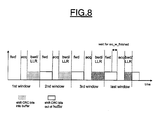
- the LLR bits are stored in a buffer BFF of windowsize (for example 53 bits for convolutional code). These bits are shifted out of the buffer into the register CRG1 during forward recursion and backward acquisition (figure 8).
- the buffer has to be implemented only once, because the LLRs of the different blocks are calculated serially. So only the shaded blocks in figure 7 are multiple instantiated.
- the MAP algorithm minimizes the probability of bit-errors, basing the decision for each bit on the knowledge of the complete block.
- the starting point for the forward recursion is always known, because we start the calculation with the alpha recursion. Furthermore the starting points for the following window is known, because we already calculated the state metrics and stored them in the alpha RAM. For backward recursion we need acquisition to get the appropriate starting points when calculating the backward recursion for the window. So we normally do the normal (full) acquisition to initialize the backward recursion. This is done until we get to the last two windows. These windows are somewhat special:
- the calculation scheme has to be preferably changed.
- the individual block lengths are not calculated serially, but in parallel. This is shown in figure 9.
- the actual stored alpha values are used for calculating all possible LLRs of this window. This way, we have only one forward recursion for all the different transport formats, only the backward recursion/LLR calculation is individual. Furthermore even some backward recursion/LLR calculations are done only once for more than one block size. So we have a total reuse of all so far calculated alpha values and the possibility of partial reuse of calculated beta values and LLRs.
- the absolute values of the last LLR can be used to distinguish between two or more blocks with a correct CRC. These values have to be stored additionally.
- Figure 9 shows the windowing scheme for the already mentioned example for two different block sizes 108 and 120.
- the processing starts with forward recursion for the first window.
- the backward recursion/LLR calculation follows.
- the forward recursion is only done once, the alpha state metrics are valid for both block sizes.
- the second block size is larger than the sum (window size+acquisition length)
- the backward recursion/LLR calculation is valid for both blocks. So the first window processing (forward recursion, backward acquisition, backward recursion/LLR calculation) is completely reused for both block sizes.
- the next window starts as usual with forward recursion. Because this is the last but one window for the first block size (108) in this example, there is no full acquisition but the tail bit processing and a partial acquisition. Afterwards the backward recursion/LLR calculation for the second window follows. These calculated LLRs are individual for the first block size and can't be reused. So for the second block size a separate backward acquisition and backward recursion/LLR calculation has to be performed. In our example the acquisition also consists of tail bits and partial acquisition.
- the next window starts with the forward recursion.
- the forward recursion is always done for the whole data, so it is either a complete window or for the last window consists of the remaining bits. So in our example it is done for the remaining 14 bits.
- the last backward processing for block size 108 starts with the acquisition (done with tail bits) and then the backward recursion/LLR calculation. After all LLRs for block size 108 are calculated the results of the final CRC is available.
- the last backward processing for block size 120 is done similar.
- step 100 "shift (i,...i max )” means that the calculated LLR bits are stored in all the CRC registers CRG1 respectively associated with all the possible formats (i min ...i max ). However, in steps 101 and 102, “shift(i)” means that the LLR bits are stored in the CRC register associated to the current format i.
- This decoder is a combined Turbo-code/convolutional code decoder, as for example the one which has been disclosed in European patent application n° 0 201 9974.1.
- a Turbo code encoder consists of two constituent convolutional encoders and an interleaver.
- the convolutional codes are fixed to be the RSC codes of rate 1/2 and generator polynomials (13,15/(octal notation) introduced before.
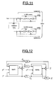
- FIG. 11 shows the detailed UMTS Turbo code encoder.
- the trellis termination leads each encoder into its final state separately. This dissolves the dependency between the systematic information of the first and second encoder for the tailbits, because these lead each encoder independent from the other by activating the respective switch, see figure 11. Hence the last six bits per encoder (systematic and parity for each) have to be transmitted separately. This results in a total overhead of 12 bits per block.
- Decoding Turbo codes by searching the most likely codeword is far too complex. Therefore iterative decoding is advised.
- the two convolutional codes are decoded separately. While doing this, each decoder incorporates information that has been gathered by the other. This "gathering of information” is the exchange of soft-output values, where the bit-estimates of one unit are transformed into a priori information for the next.
- the decoders hence have to be soft-input soft-output (SISO) units.
- LLR Log-Likelihood-Ratio
- the sign shows whether this bit is supposed to be one or zero whereas the confidence in the decision is represented by the magnitude.
- the confidence of one decoder in a bit to have a certain value biases the initial guess of the other.
- Figure 12 shows such a Turbo code decoder consisting of two MAP decoders, an interleaver and a deinterleaver. Feeding the input of one decoder as a priori information input to the next enables the improvement over the decoding iterations. It also gave Turbo codes their name, as it resembles the "feedback-of-exhaust" used in combustion turbo engines. Inputs to the decoder are the received channel values (systematic, parity1 and parity2); during the very first MAP1 operation, the a priori information is set to zero.
- equations 2.1-2.7 are used for Turbo decoding as well as equations 2.8-2.12 and equations 3.1-3.2.
- mapping is '1' ⁇ '-1' and '0' ⁇ '1'.
- the combined decoder CTD comprises Turbo-code decoding means TCDCM for performing Turbo-code decoding, and convolutional code processing means CCDCM for performing convolutional code.
- Turbo-code and convolutional code decoding means comprise common processing means CCPR implementing MAP algorithm and having a first configuration dedicated to Turbo-code decoding and a second configuration dedicated to convolutional code decoding.
- Said common processing means CCPR or MAP unit form a Soft-in-Soft-out unit (SISO unit) on which MAP1 and MAP2 operations are done serially for turbo decoding, until a stopping criterion is fullfilled.
- SISO unit Soft-in-Soft-out unit
- the Turbo-code decoding means TCDM comprises conventional interleaving means IL.
- the combined decoder CTD comprises metrics memory means referenced as TC alpha-RAM for storing forward state metrics associated to the states of a first trellis (8 states here), said forward state metrics being delivered by the processing means CCPR in its first configuration (Turbo decoding).
- Input/output memory means referenced as CC I/O RAMs are provided for storing input and output data delivered to and by the processing means CCPR in its second configuration, i.e. for CC decoding.
- adaptable memory means ADMM are used for storing input and output data delivered to and by said processing means CCPR in its first configuration (Turbo-code decoding), and for storing forward state metrics associated to the states of a second trellis (256 states here) and delivered by said processing means CCPR in its second configuration (convolutional code decoding).
- Control means CDRLM configurate said common processing means CCPR in its first or second configuration depending on the kind of code, and memory control means CTMM address differently said adaptable memory means ADMM depending on the configuration of said common processing means CCPR.
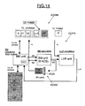
- Figure 14 illustrates more in detail thus internal structures of the common processing means CCPR.
- the processing means CCPR comprise essentially three major of calculation unit, i.e., the BM unit that calculates the branch metrics BM and controls the complete I/O RAMs and alpha RAM ; the state metric unit which calculates 8 state metrics SM in parallel with 8 add-compare-select (ACS) units ; the LLR unit, which calculates the LLRs in a pipelined manner.
- the BM unit that calculates the branch metrics BM and controls the complete I/O RAMs and alpha RAM
- the state metric unit which calculates 8 state metrics SM in parallel with 8 add-compare-select (ACS) units
- the LLR unit which calculates the LLRs in a pipelined manner.
- Input/output memory means CC I/O RAMs for convolutional decoding
- the input RAMs consist in three RAMs referenced as G0_RAM G1_RAM and G2_RAM according to the respective CC input data.
- Output RAM is CCLLR_RAM.
- the RAM-sizes are 512*6 bits.
- the alpha state metric RAM for TC decoding is a dedicated 64*88bit RAM (alpha_RAM).
- the adaptable memory means ADMM is used either for storing input and output data for Turbo-code decoding or for storing forward state metrics in the convolutional code decoding.
- these adaptable memory means comprises a lot of elementary memories as well as an additional memory means Add.
- the input and output data delivered to and by the processing means CCPR in its first configuration comprises for each received sequence, g different blocs of N1 words of b1 bits.
- N2 times b2 is equal to the product of W (windowsize) with the number of states of the trellis and, with the number of bits for each state.
- W is equal to 54 or the convolutional code, 64 for the Turbo-code.
- the number of states is equal to 8 for the Turbo-code and to 256 for the convolutional code.
- the number of bits for each state is equal to 11.
- N2 is equal to 1728 whereas b2 is equal to 88.
- the additional memory Add is adapted to store 1728 words of 16 bits.
- the memory control means address the adaptable memory means ADMM in said first configuration (Turbo-code decoding) such that each bloc of 5120 words of 6 bits is written in or read from its dedicated group of 3 elementary memories.
- said memory control means address said adaptable memory means ADMM in said second configuration (convolutional code decoding) such that the twelve elementary words of said forward state metrics are respectively stored in the twelve elementary memories of the main memory means at the same address, whereas the additional elementary word of the forward state metrics (the 16 other bits) is stored in the additional memory means at the same address.
- each of the I/O RAMs of the TC is split into 3 separate RAMs. These RAMs are the concatenated to form the required bitwidth for the storage of 8 state metrics in parallel.
- We need 88 bits (8* 11 bit), the I/O RAMs are 6 bit wide so we get 4*3*6 bit 72 bit. Therefore we need an additional 16bit RAM to form the CC alpha RAM. This RAM sharing enables us to get a sufficient windowsize for CC decoding.
- the systematic input data is stored in X_RAM1, X_RAM2, X_RAM3, the parity input data is stored in Y1_RAM1, Y1_RAM2, Y1_RAM3, and the interleaved parity input data is stored in Y2_RAM1, Y2_RAM2, Y2_RAM3.
- the TC output RAMs are LLR_RAM1, LLR_RAM2 and LLR_RAM3.
- the MSB represents the output hard decision, whereas the LSB represent the extrinsic information/LLR soft decision (depending on actual decoding progress). This enables a stopping of the decoding after MAP1 CRC check.
- the common processing means comprises a branch metric unit for calculating in each first and second configurations the branch metrics associated to the branches of the corresponding trellis (see eq. 2.17 for turbo code).
- the transfer of TC input data samples to the CTD decoder is done in the following order : X 1 , Y 1 / 1, Y 2 / 1, X 2 , Y 1 / 2, Y 2 / 2,........ X Bi , Y 2 / Bi , TailBits B i is the number of bits in the i -th code block.
- the parity data RAMs Y1 and Y2 are filled sequentially, the respective three tailbits are just appended.
- the systematic data RAM X is also filled sequentially, because there are six tailbits in total, the tailbits for the first encoder are appended first, then the tailbits for the second encoder follow.
- the input sequence for CC decoding is simpler, because there is only one tail sequence.
- the tailbits are just appended to the respective RAM.
- the different steps of the windowing scheme can be divided into further sub-steps.
- the calculation of the branch metrics is the prerequisite for the calculation of the state metrics.
- the memory control mean therefore addresses the input RAMs to calculate the respective branch metrics.
- the used naming convention is based on the binary representation of the pair [systematic/parity information] ⁇ 0,1 ⁇ resp. [G0/G1], [G0/G1/G2].
- X, Y, LLR, G0, G1, G2 represent the individual data stored in this RAMs (e.g. the content of the LLR-RAM is the extrinsic information).
- the branch metric calculation is very simple, two additions for TC and one resp. four additions (calculation of branch7 reuses a previously addition, e.g. G0+G1) for CC.
- the BM unit interacts with the external interleaver to fetch the appropriate addresses.
- a dedicated LLR-cache is needed as well as a dedicated LLR-register.
- the common processing means comprises a configurable state metrics unit SM.
- the configurable state metrics units SM comprises
- the ACS architecture illustrated on figure 16 calculates eight state metrics in parallel out of the branch metrics and the previous state metrics according to equations 2.10 and 2.11. This is done with 8 ACS (Add, Compare, Select) units based on a modmin-procedure (the MODMIN blocs perform the min* operator).
- This ACS architecture is used for forward as well as for backward recursion for both Turbo code and Convolutional code. Because of the different trellis diagrams, the flexibility is achieved with multiplexers for the incoming branch metrics (bmux) and state metrics (smux). These multiplexers are controlled externally as explained thereafter.
- the eight ACS units need sixteen branch metric + state metric sums, therefore sixteen bmux multiplexers are provided. Each of these bmux multiplexers can select among eight branch metrics (because CC rate 1/3 needs eight different branch metrics in total). However, because of a particular state metric distribution not sixteen but only twelve smux state metric multiplexers are needed. Furthermore this state metric distribution leads to only 2:1 smux multiplexers, because the setting is valid for either CC forward recursion/TC backward recursion or CC backward/TC forward recursion. There is no additional multiplexing of the calculated state metrics. In case of forward recursion, the new state metrics are always in ascending order.
- Figure 16 shows the general architecture of the acs architecture.
- Sm1-sm8 denote the 8 parallel input state metrics at one timestep
- bm0-bm7 denote the up to 8 different branch metrics.
- the smux setting for TC forward/CC backward is marked bold.
- the output of this unit are the new state metrics as well as the LLR-metrics ( ⁇ state metric + branch metric) for the LLR calculation.
- the multiplexer of the state metrics unit are controlled by a specific machine, not shown for reason of simplification.
- the state metric multiplexer smux controlling is very simple. There are only two different settings, either for TC forward recursion/CC backward recursion or for TC backward recursion/CC forward recursion.
- the controlling of the branch metric multiplexer bmux is more complex and done in the FSM. Each sequence (32 steps) depends on the chosen rate as well as on the actual operation (forward recursion or backward recursion).
- the upper modmin-tree calculates the minimum of all states reached by input '1' (LLR1), the lower one the minimum reached by input '0' (LLR0).
- Parts of the LLR calculation for TC are reused for Convolutional decoding, see figure 17 (not shown are the multiplexer for the input values and the adder for calculating the sums).
- the input '0' resp. '1' determines the state number.
- the upper two modmin units calculate the minimum of the four state metric sums reached by input '1' (onestates), the lower two the minimum of input '0' (zerostates). Therefore the inputs are the alpha state metrics from the alpha-RAM and the beta metrics from the AXMM memory.
- the combined decoder comprises a global control unit which controls the decoding process on MAP level. Because TC decoding is done in an iterative matter, the number of iterations depends on the actual decoding status. Therefore after each MAP operation a stopping criterion is checked. This stopping criterion can either be the selected total number of half-iterations, a correctly detected CRC-sum (only after MAP1) or an early detection of undecodable blocks based on the mean value criterion. The particular decoding steps for TC are shown in figure 18. In case of CC decoding only one MAP1 operation is needed.
- This handshake mode allows step-by-step execution of the decoding steps and on-demand memory flush.
Landscapes
- Physics & Mathematics (AREA)
- Probability & Statistics with Applications (AREA)
- Engineering & Computer Science (AREA)
- Theoretical Computer Science (AREA)
- Computer Networks & Wireless Communication (AREA)
- Signal Processing (AREA)
- Computing Systems (AREA)
- Error Detection And Correction (AREA)
- Detection And Prevention Of Errors In Transmission (AREA)
- Detection And Correction Of Errors (AREA)
Abstract
The actual transport format is ex ante unknown and belonging
to a set of MF predetermined reference transport formats. The signal
comprises a data block having an ex ante unknown number of bits
corresponding to said ex ante unknown transport format, and a cyclic
redundancy check (CRC) field containing a transmitted CRC word. The
method comprises decoding said signal using a Maximum-a-Posteriori
algorithm, said decoding step including decoding said signal
considering respectively the MF possible reference formats and
respectively delivering MF corresponding groups of soft output
information, calculating from each group of soft output information a
calculated CRC word and comparing said calculated CRC word with
said transmitted CRC word, selecting all the groups for which said
calculated CRC word is equal to said transmitted CRC word, and
selecting the actual transport format of the encoded signal from at
least one soft output information among the last ones of each selected
group.
Description
- The invention relates in general to channel coding and decoding techniques, especially convolutional codes, and more particularly to the blind transport format detection (BTFD).
- An application of the invention is directed in general to the field of wireless communication systems, and more particularly to the CDMA systems such as the different CDMA based mobile radio systems like CDMA 2000, WCDMA (Wide Band CDMA) or the IS-95 standard.
- The third generation mobile radio system specifies Convolutional codes as well as Turbo-codes as channel coding techniques [3GPP, Technical Specification Group Radio Access Network ; Multiplexing and channel coding (FDD) ; (3G TS 25.212 version 3.5.0(2000-12)), Release 1999].
- The UMTS standard defines, beside the TFCI (Transport Format Combination Indicator) base transport format detection, a possibility of blindly detect the transport format in use. More details can be found in 3GPP, Technical Specification Group Radio Access Network; Multiplexing and channel coding (FDD); (3G TS 25.212 version 4.3.0 (2001-12)), Release 4.
- This option is used in order to reduce the TFCI symbol overhead in the transmission frame and thus to increase the air load. Further, as indicated in the UMTS standard, the explicitly blind detected transport channels have to be coded using a convolutional code.
- Generally speaking, the blind transport format detection is based in the use of the CRC (Cyclic Redundancy Check) words. An example of such detection can be found in the annex of the above mentioned 3GPP document. The main idea is to use a Viterbi decoder for decoding the different possible block sizes corresponding to the possible transport formats which can be used in the transport channel under investigation. Then, a CRC word (Cyclic Redundancy Check word), has to be checked for all possible block sizes. A correct CRC determines the correct block size. For large CRC length, the CRC check is sufficient to determine the correct block. However, in the case of smaller CRCs, like 8 or 12 bits, an additional metric has to be deployed in order to distinguish between two or more blocks with a correct CRC. And, when a Viterbi decoder is used, an additional calculation is needed for calculating this additional metric.
- The invention intends to provide a solution to this problem and proposes a different method of blindly detecting a transport format of an incident convolutional encoded signal.
- Generally speaking, said transport format being ex ante unknown and belonging to a set of MF predetermined reference transport formats, said signal comprising a data block having an ex ante unknown number of bits corresponding to said ex ante unknown transport format, and a Cyclic Redundancy Check (CRC) field, containing a transmitted CRC word, the method according to the invention comprises decoding said signal using a Maximum-a-Posteriori algorithm, said decoding step including decoding said signal considering respectively the MF possible reference formats and respectively delivering MF corresponding groups of soft output information, calculating from each group of soft output information a calculated CRC word and comparing said calculated CRC word with said transmitted CRC word, selecting all the groups for which said calculated CRC word is equal to said transmitted CRC word, and selecting the actual transport format of the encoded signal from at least one soft output information among the last ones of each selected group.
- Thus, the invention uses already calculated soft output information (LLR information) as additional metric to distinguish between two or more blocks with a correct CRC. This is possible since the proposed architecture uses a MAP base decoder for decoding the CC code. In this case, no additional metric calculation is needed like in the case of the Viterbi decoder.
- According to an embodiment of the invention, the actual transport format of the encoded signal is selected from the last soft output information of each selected group.
- The actual transport format is for example the reference format having the greatest last soft output information.
- However, other possibilities exist for selecting the actual transport format. For example, we can use the last but one soft output information, or the last but one and the last soft output information. Another possibility consists in combining one of the last soft output information with the minimum soft output information.
- According to an embodiment of the invention, said decoding step comprises calculating state metrics, and all the data blocks are decoded in parallel window-by-window on sliding windows having a predetermined size, and at least some of the states metrics calculated on a window are valid for all the data blocks.
- According to a preferred embodiment of the invention, said decoding step comprises for each window calculating forward state metrics during a forward recursion, performing a backward acquisition having a predetermined acquisition length, calculating backward state metrics during a backward recursion and calculating soft output information in the reverse order, and for each window only one forward recursion is performed which is valid for all the transport formats.
- According to an embodiment of the invention, the first window processing including forward recursion, backward acquisition, backward recursion and soft output calculation, is completely valid for all data blocks having a size larger than the sum of the window size and the acquisition length.
- In other words, according to particular embodiments of the invention, there is a complete reuse of forward state metric calculation for all different block sizes and partial reuse (if possible) of backward state metric calculation and LLR calculation for different block sizes.
- The invention proposes also a convolutional code decoder, comprising
- input means for receiving an convolutional encoded signal having an ex ante unknown transport format belonging to a set of MF predetermined reference transport formats, said signal comprising a data block having an ex ante unknown number of bits corresponding to said ex ante unknown transport format, and a Cyclic Redundancy Check (CRC) field containing a transmitted CRC word,
- convolutional code decoding means implementing a Maximum-a-Posteriori algorithm for decoding successively said signal by considering respectively successively the MF possible reference formats and comprising a Log-Likelihood-Ratio unit for successively respectively delivering MF corresponding groups of soft output information,
- blind transport format detection means comprising a Cyclic Redundancy Check unit for calculating from each group of soft output information a calculated CRC word and comparison means for comparing said calculated CRC word with said transmitted CRC word, first selection means for selecting all the groups for which said calculated CRC word is equal to said transmitted CRC word, and second selection means for selecting the actual transport format of the encoded signal from at least one soft output information among the last ones of each selected group.
- According to an embodiment of the invention, said second selection means are adapted to select the actual transport format of the encoded signal from the last soft output information of each selected group.
- According to an embodiment of the invention, said convolutional code decoding means are adapted to calculate state metrics, all the data blocks are decoded in parallel window-by-window on sliding windows having a predetermined size, and at least some of the state metrics calculated on a window are valid for all the data blocks.
- According to an embodiment of the invention, said convolutional code decoding means are adapted for each window, to calculate forward state metrics during a forward recursion, to perform a backward acquisition having a predetermined acquisition length, to calculate backward state metrics during a backward recursion, and for each window only one forward recursion is performed which is valid for all the transport formats.
- According to an embodiment of the invention, the first window processing including forward recursion, backward acquisition, backward recursion and soft output calculation, is completely valid for all data blocks having a size larger than the sum of the window size and the acquisition length.
- The code decoder according to the invention can be a combined Turbo-code/convolutional code decoder further comprising Turbo-code decoding means for performing Turbo-code decoding.
- And, according to an embodiment of the invention, said Turbo-code and convolutional code decoding means comprises common processing means having a first configuration dedicated to Turbo-code decoding and a second configuration dedicated to convolutional code decoding. And said decoder further comprises :
- metrics memory means for storing state metrics associated to the states of a first trellis and delivered by said processing means in its first configuration,
- input/output memory means for storing input and output data delivered to and by said processing means in its second configuration,
- adaptable memory means for storing input and output data delivered to and by said processing means in its first configuration, and for storing state metrics associated to the states of a second trellis and delivered by said processing means in its second configuration,
- control means for configurating said common processing means in its first or second configuration depending on the kind of code, and
- memory control means for addressing differently said adaptable memory means depending on the configuration of said common processing means.
- Said common processing means may implement a Maximum-A posteriori (MAP) algorithm.
- And, the MAP algorithm implemented is for example a so-called LogMAP algorithm or a so-called MaxLogMAP algorithm.
- The convolutional code decoder according to the invention may be advantageously realized by an integrated circuit.
- The invention proposes also a terminal of a wireless communication system including a decoder as defined above.
- This terminal may form a cellular phone or a base station.
- Other advantages and features of the invention will appear on examining the detailed description of embodiments, these being in no way limiting and of the appended drawings in which :
- figure 1 shows the structure of the two different NSC used in UMTS for Convolutional encoding,
- figure 2 shows a part of a trellis which represents the possible transitions in one time step,
- figure 3 shows a receiving chain of mobile phone including a decoder according to the invention,
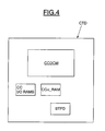
- figure 4 shows very diagrammatically the internal structure of a first embodiment of a decoder according to the invention,
- figure 5 shows more in detail a part of a decoder according to the invention,
- figure 6 illustrates diagrammatically possible transport formats,
- figure 7 shows diagrammatically a part of blind detection means according to the invention,
- figure 8 shows diagrammatically a CRC processing scheme according to the invention,
- figure 9 shows diagrammatically a windowing scheme according to the invention,
- figure 10 illustrates a flow chart of a blind detection according to the invention,
- figure 11 shows an UMTS Turbo-code encoder,
- figure 12 shows a generic Turbo decoder,
- figure 13 shows very diagrammatically the internal structure of a decoder according to a second embodiment of the invention,
- figure 14 shows more in detail a part of the decoder illustrated in figure 13,
- figure 15 shows more in detail an adaptable memory belonging to a decoder according to the invention,
- figure 16 shows diagrammatically an ACS unit architecture,
- figure 17 shows an LLR unit belonging to a combined decoder according to the invention,
- figure 18 shows global control steps for Turbo-code decoding according to the invention.
- Convolutional encoding is performed by calculating the modulo-2 sum of the input values of the current and/or selected previous time steps. Implementation therefore is straightforward and mainly consists of shift register and a couple of exclusive-OR gates. Through the way those are switched, different kinds of convolutional codes can be realized:
- Systematic Codes: One of the output streams is equal to the input stream, the systematic information.
- Non-Systematic Codes (NSC): Each output is a parity information. Parity information is produced by taking the modulo-2 sum of shift register entries stating the history of the encoding process.
- Recursive Codes: A special parity signal is produced and fed back in conjunction with the systematic input.
- Non-Recursive Codes: No such feedback loop exists.
-
- An instance of a convolutional encoder is defined by a combination of these properties, the memory depth (constraint length) and the logical functions used to produce the parity information. These properties are described through generator polynomials.
- Figure 1 represents the structure of two different NSC used in UMTS for Convolution and Convolutional encoding. Furthermore, two different rates have to be considered. The rate 1/2 convolutional encoder (a) has two outputs, whereas the rate 1/3 encoder (b) has three outputs.
- With the value of the current time-step available, M = K-1 flip-flops are needed to store the encoder history. This gives rise to an interpretation of the encoder as finite-state machine (FSM). It shows a behavior equivalent to a Mealy-automaton. The likelihood of a transition between two states is the key to the decoding of convolutional codes.
- A code trellis is the unrolled state chart of a finite-state machine. The number of states the encoder can be in (N) is a function of the constraint length K:
- Depending on the nature of the code (RSC, NSC,...) only certain transitions are possible. A trellis is used to depict those transitions. In figure 2, a part of a trellis is shown, that represents the possible transitions in one time-step. Instead of the usual tree-structure used to display state-charts, the trellis combines states which are equivalent. Solid lines in figure 2 stand for transitions due to the input of a systematic bit of "0" whereas dashed lines represent those caused by a "1".
- On convention, every encoding process starts in the all-zero state.
- For the considered codes the initial state of the trellis is always known to be the all-zero state. Without taking any precautions, the encoder ends in an arbitrary state, leaving no hint where to start the backward recursion. This can be counteracted by driving the encoder into a defined final state. Reaching the final state (e.g. the all-zero state) can be achieved by appending a sequence, which steers the encoder towards the final state as fast as possible. This sequence is also depending on the state the encoder is in after the last information bit has been coded. The length of this sequence is equal to K-1; the transmitted bits are called tailbits.
- 2.1 Decoding convolutional codes is keeping track of the transitions that took place in the encoder. From those the input symbols which have been sent are deducted. Due to the degradations caused by the channel, only estimates of the systematic and parity bits are available, which will both be called channel values here. There are two different kinds of outputs:
- Hard values: they merely indicate if a symbol is supposed to be "1" or "0".
- Soft values: These also deliver a measure for the reliability of the decision (the hard decision is extend by the probability that the decision is correct).
-
- Based on the channel values, probabilities can be computed that certain combinations of systematic and parity bit occurred. From this and considering the encoder history, the probability that the encoder was in a given state at a given time-step can be computed.
- Two approaches exist to deal with those state-probabilities. The maximum likelihood based Viterbi algorithm uses them to search the most likely code-word. For this it traverses the trellis from the all-zero state to the end state and looks for the most likely sequence. The states chosen for the survivor path indicate the most likely sequence of symbols that has been send. Hence a Viterbi Decoder is a sequence estimator.
- The maximum-α-posteriori (MAP) algorithm on the other side estimates the probability that the encoder was in the given state and that the current state leads to the final state given the remainder of the channel values. This can be efficient computed by a forward and backward recursion over the trellis. Afterwards, for each bit the probabilities for those states associated with a systematic "0" are added and compared to those associated with a "1". The symbol with the higher probability is assumed to be the sent one. As this works on bit rather than on sequence level, it is called symbol estimation.
- The name Maximum-A-Posteriori stems from the fact that the estimation of the bits is based on the whole receiver sequence. It is done after all the information is in.
- Equation 2.1 shows the output of such a MAP decoder.
- Bahl et al. described in [L. Bahl, J. Cocke, F. Jelinek, and J. Raviv. Optimal Decoding of Linear Codes for Minimizing Symbol Error Rate. IEEE Transaction on Information Theory, IT-20:284-287, march 1974] an efficient algorithm for the MAP decoder, which is based on recursions operating on the trellis in forward and backward recursion. That algorithm is commonly referred to as MAP or BCJR algorithm:
- Let Rk denote the input of the MAP, with
R = (R 1 ,...,Rk ,...RN) where N is the length of the block, then the BCJR-algorithm computes the a-posteriori probabilities (APP)for each data symbol dk after reception of the symbol sequence
R . - It is computed using two probabilities: One, that the encoder has reached state S m / k, withafter k received symbols:
 and another, that the remainder of the input sequence will lead the encoder to the final state given the state S m' / k+1 at time k+1:

- For this, the probability of a transition from state S m / k to S m' / k+1 has to be known. It is depending on the code structure, the channel model and the received symbols Rk :

- Using γ, α and β can be computed recursively by:


- A known start and final state are necessary for the BCJR algorithm to perform optimally. If the trellis is not terminated, all states have to be assumed to have equal probability for k = N.
- The a-posteriori probability itself can be expressed as

- When the constituent encoder is a NSC, this equation can be simplified because the state number can be used to identify a state reached by input dk = 1 or dk = 0.

- The large number of multiplications involved in the computation of the APP makes it less attractive for implementation. Therefore the MAP algorithm has to be transformed to the logarithmic domain, where it becomes the LogMAP algorithm, which increases numerical stability and eases implementation, while not degrading the error correction performance.
- The transformation of multiplications into additions is the motivation for defining the MAP algorithm in the Log-Domain. A problem is posed by the additions. Using the Jacobian logarithm, the additions are substituted by a new operator:
- Similar the negative logarithm can be taken, this leads to
- For more than two operands, the max* is applied recursively. Since the operator is associative, a tree-like evaluation can be employed, which is advantageous for hardware implementation. The sub-optimal MaxLogMAP algorithm is obtained by using the approximation
- Using the max* operation, the recursions become:
- Let ln(α k (m')) from now on be denoted as
α k (m') (accordingly for β and γ), then the recursions take the form: - Similar we get:

- Computation
γ of includes the estimation of channel values. An optimised branch metric calculation is used. In case of an NSC encoder the channel values are parity informations. Dependant on the rate there are only four resp. eight different values per k in total theγ can take. The code-structure alone determines, which of them is assigned to which transition. After skipping constant factors and making additional algebraic transformations we get (eq. 2.13) : - Rate 1/2:
- Rate 1/3:
-
- This simplifies the implementation significantly, as only up to four terms have to be computed from the channel data. One term can be dropped completely and the last one be computed from two others. The scaling factor 4Es / N 0 is multiplied externally by usage of a working point.
- The MAP algorithm minimizes the probability of bit-errors, basing the decision for each bit on the knowledge of the complete block of samples, that is a posteriori. It has been shown, however, that a sliding window technique, where a window slides in direction of increasing bit positions k, delivers almost the same communication performance as the original MAP decoder. Then the decisions are based on a subblock beginning at the first bit position in the complete block and ending at the last position in the sliding window. The MAP algorithm can decide all bits belonging to the window, less the bits contained in the last portion of that window. Those bits in the last portion are decided when the window has moved to its next position(s). If only the bits in the middle part get decoded, then the window does not even have to slide (that is to move steadily in one direction).
- When we look at the equations of the MAP algorithm, one can easily identify four subtasks:
- Calculation of the branch metrics (step 1)
- Calculation of the forward state metrics during forward recursion (step 2)
- Calculation of the backward state metrics during backward recursion (step 3)
- Calculation of the soft outputs (step 4)
-
- The data dependencies between these steps are as follows: both recursions (step 2 and step 3) and the soft output calculation (step 4) depend on the branch metrics (step 1), and the soft output calculation step (step 4) in addition depends on the forward and backward state metrics (step 2 and step 3). All branch metrics and soft outputs of the current data block can be computed independently from each other. Only the order of computing the forward state metrics and the order of computing the backward state metrics are predefined by the direction of the respective recursion. The sequence of the recursions does not matter, since there is no data dependency between the forward and backward state metrics. The backward recursion can be processed before, in parallel to, or after (as implied above) the forward recursion. Hence, we can introduce the notion of a first and a second recursion. The metrics for the first recursion for a certain trellis step have to be stored in memory until the second recursion has produced the missing complementary metrics for computing the soft output value connected with that trellis step. Thus the decoder needs to store the first recursion metrics of the full data block. Introducing windowing, each comprising a data subblock, breaks this dependency. Decoding on a window-by-window basis permits to reduce the required memory size.
- A prerequisite for decoding on windows is the concept of "acquisition". Originally, the forward and the backward recursion of a MAP decoder start at one end of the trellis and stop at the opposite end. Upon an appropriately long acquisition phase, however, a recursion can start at any trellis step. This applies to both forward and backward recursions.
- Consider a forward acquisition commencing at trellis step k-M, where M is the acquisition depth. The forward state metrics are initialized as:

- After M recursion steps, the metrics
α k (Sk ) approach the values that would be obtained by starting the recursion from the beginning of the trellis. Now consider a backward recursion commencing at trellis step k+M. The backward state metrics are initialized as:
- In analogy to the forward recursion, after the same number of recursion steps M, the metrics
β k (Sk ) approach the values that would be obtained by starting the recursion at the end of the trellis. If the acquisition depth M is too small, then the decoding performance can be severely degraded. With M above a certain value, the decoding performance is virtually optimal. The value of M that leads to a reasonable balance between computational effort and decoding performance can be determined by simulation. - The windowsize itself has no influence on the communication performance, but on the size of the RAM for storage of the α-state metrics. Furthermore the throughput is dependant on the ratio between acquisition length and windowsize. When only one state metric calculation unit is available, the individual windows are processed sequential. It takes one clock cycle for the forward recursion and one clock cycle for the backward recursion/LLR calculation per data bit. The additional computational overhead is determined by the total number of acquisition steps. If the windowsize is equal to the acquisition length, the decoding needs one additional clock cycle per bit, resulting in total three clock cycles per bit. If the windowsize is much larger than the acquisition length, the computational overhead goes near zero, resulting in a throughput of nearly two. So the choice of the windowsize is a trade off between memory size and throughput.
- 4.1 We refer now to figure 3 which illustrates a decoder according to the invention which is incorporated in the reception chain of a cellular mobile phone TP.
- The encoded signal is being received by the antenna ANT and processed by the radio frequency stage ERF of the receiver. At the output of the ERF stage, the signal is converted into the digital domain by an A/D converter. The digital base band signal is then processed by a "rake" demodulator which is used generally in the case of a CDMA system.
- Then, the channel decoding stage includes a convolutional code decoder CTD according to the invention.
- The decoder CTD according to the invention, as illustrated on figure 4, comprises convolutional code decoding means CCDCM for performing convolutional code decoding.
- The decoding means CCDCM implements a MAP algorithm.
- Further, input/output memory means referenced as CC I/O RAMs are provided for storing input and output data delivered to and by the decoding means CCDCM.
- Further, another memory, referenced CCα-RAM, is used for storing forward state metrics (α-state metrics) associated to the states of a trellis (for example 256 states) and delivered by the decoding means CCDCM.
- At last, the decoder CCD comprises blind transport format detection means BTFD for blindly detecting the transport format used in a transport channel under investigation. The internal architecture of these means BTFD will be described more in detail thereafter.
- Figure 5 illustrates more in detail internal structure of the convolutional code decoding means CCDCM.
- These means comprise essentially three major calculation units, i.e. :
- a BM unit that calculates the branch metrics BM and controls the CC I/O RAMs. The calculation of the branch metrics is performed according to equation 2.13, depending on the value of the rate,
- the state metric unit SM which calculates state metrics SM according to equations 2.10 and 2.11,
- the LLR unit, which calculates the soft output information (LLRs) in a pipeline manner, according to equations 2.12a.
- The input RAMs consist in three RAMs referenced as GO-RAM, G1-RAM and G2-RAM according to the respective convolutional code input data. Output RAM is a LLR-RAM.
- The blind detection of the transport format will be now described more in detail with reference to figures 6-10.
- In figure 6, the structure of a coded block in the case of BTFD is depicted.
- The transport channel under consideration has MF different transport formats TF1 to TFMF and thus MF different coded blocks sizes. A coded block contains a CRC field (transmitted CRC word) and the data bit field. The CRC field in each of the different blocks has the same size and thus uses the same polynomial. In the presented case the coded block only contains one CRC at the end. The DTX field can be considered as being noise.
- The blind transport format detection means comprises a Cyclic Redundancy Check Unit CRCU (figure 7) for calculating from each group of soft output information (LLR) corresponding to each transport format, a calculated CRC word. This calculated CRC word is stored in a CRC register CRG1. Therefore, certain input parameters are necessary, which are the length of the CRC and the CRC polynomials.
- The transmitted CRC word (CRC sum) which is attached to the data block in reverse order during the encoding, is stored in the register CRG2.
- Comparison means are adapted to compare the content of the register CRG1 with the register CRG2. When equal, the CRC check is positive.
- The LLR bits are stored in a buffer BFF of windowsize (for example 53 bits for convolutional code). These bits are shifted out of the buffer into the register CRG1 during forward recursion and backward acquisition (figure 8).
- This architecture can be extended to check up to MF=16 different block sizes by usage of total 16 CRC check units. The buffer has to be implemented only once, because the LLRs of the different blocks are calculated serially. So only the shaded blocks in figure 7 are multiple instantiated.
- As mentioned before, a sliding window approach is used. The MAP algorithm minimizes the probability of bit-errors, basing the decision for each bit on the knowledge of the complete block. Originally the forward and backward recursion of a MAP decoder start at one end of the trellis and stop at the opposite end. This starting points are known for the forward recursion (state 0) and if tailing is applied as in UMTS, we also know the end point (= starting point for backward recursion) of the trellis (state 0). However upon an appropriate long acquisition phase we can start at any trellis step. This applies for both forward and backward recursion. The starting point for the forward recursion is always known, because we start the calculation with the alpha recursion. Furthermore the starting points for the following window is known, because we already calculated the state metrics and stored them in the alpha RAM. For backward recursion we need acquisition to get the appropriate starting points when calculating the backward recursion for the window. So we normally do the normal (full) acquisition to initialize the backward recursion. This is done until we get to the last two windows. These windows are somewhat special:
- last window: We don't do a normal acquisition, because we don't have data to do so. But we don't need this at all, because we have the tailbits, which are used to give us the init state metrics for backward recursion.
- last but one window: It could happen, that there are not enough data bits left to do a full acquisition. But this is no problem because we simply start with the tail bits and then process the remaining acquisition steps. Than we proceed as usual with backward recursion/LLR calculation.
- It would be possible to adapt this scheme for the blind transport format detection. However, if we consider for example two transport formats of sizes 108 and 120, then, when we determine the LLRs for block length 108, we cannot calculate the LLRs for block length 120 without starting the forward recursion from the second window. And the initialization values for the forward recursion have to be stored in specific memory, otherwise, we have to start the forward recursion from the beginning.
- When one wants to reuse as much as possible, the calculation scheme has to be preferably changed. The individual block lengths are not calculated serially, but in parallel. This is shown in figure 9. The actual stored alpha values are used for calculating all possible LLRs of this window. This way, we have only one forward recursion for all the different transport formats, only the backward recursion/LLR calculation is individual. Furthermore even some backward recursion/LLR calculations are done only once for more than one block size. So we have a total reuse of all so far calculated alpha values and the possibility of partial reuse of calculated beta values and LLRs. As there can be more than one block length with correct CRC, the absolute values of the last LLR can be used to distinguish between two or more blocks with a correct CRC. These values have to be stored additionally.
- Figure 9 shows the windowing scheme for the already mentioned example for two different block sizes 108 and 120. The processing starts with forward recursion for the first window. After the backward acquisition the backward recursion/LLR calculation follows. The forward recursion is only done once, the alpha state metrics are valid for both block sizes. Because the second block size is larger than the sum (window size+acquisition length), the backward recursion/LLR calculation is valid for both blocks. So the first window processing (forward recursion, backward acquisition, backward recursion/LLR calculation) is completely reused for both block sizes.
- The next window starts as usual with forward recursion. Because this is the last but one window for the first block size (108) in this example, there is no full acquisition but the tail bit processing and a partial acquisition. Afterwards the backward recursion/LLR calculation for the second window follows. These calculated LLRs are individual for the first block size and can't be reused. So for the second block size a separate backward acquisition and backward recursion/LLR calculation has to be performed. In our example the acquisition also consists of tail bits and partial acquisition.
- The next window starts with the forward recursion. The forward recursion is always done for the whole data, so it is either a complete window or for the last window consists of the remaining bits. So in our example it is done for the remaining 14 bits. Then the last backward processing for block size 108 starts with the acquisition (done with tail bits) and then the backward recursion/LLR calculation. After all LLRs for block size 108 are calculated the results of the final CRC is available. The last backward processing for block size 120 is done similar.
- The proposed general processing flow for BTFD is shown in figure 10.
- In step 100, "shift (i,...imax)" means that the calculated LLR bits are stored in all the CRC registers CRG1 respectively associated with all the possible formats (imin...imax). However, in steps 101 and 102, "shift(i)" means that the LLR bits are stored in the CRC register associated to the current format i.
- A second embodiment of a decoder according to the invention will be now described. This decoder is a combined Turbo-code/convolutional code decoder, as for example the one which has been disclosed in European patent application n° 0 201 9974.1.
- The main features of such a combined decoder will be now described.
- However, before describing in detail the internal architecture of such combined decoder, some general considerations on Turbo-code encoding and decoding will be now described.
- 5.1 A Turbo code encoder consists of two constituent convolutional encoders and an interleaver. The convolutional codes are fixed to be the RSC codes of rate 1/2 and generator polynomials (13,15/(octal notation) introduced before.
- The systematic information of the second encoder is not transmitted because it can be reconstructed (by deinterleaving) from the systematic output of the first encoder. By this a rate of R = 1/3 is achieved. Figure 11 shows the detailed UMTS Turbo code encoder. The trellis termination leads each encoder into its final state separately. This dissolves the dependency between the systematic information of the first and second encoder for the tailbits, because these lead each encoder independent from the other by activating the respective switch, see figure 11. Hence the last six bits per encoder (systematic and parity for each) have to be transmitted separately. This results in a total overhead of 12 bits per block.
- Decoding Turbo codes by searching the most likely codeword is far too complex. Therefore iterative decoding is advised. The two convolutional codes are decoded separately. While doing this, each decoder incorporates information that has been gathered by the other. This "gathering of information" is the exchange of soft-output values, where the bit-estimates of one unit are transformed into a priori information for the next. The decoders hence have to be soft-input soft-output (SISO) units.
- The confidence in the bit estimation is represented as a Log-Likelihood-Ratio (LLR):
- The sign shows whether this bit is supposed to be one or zero whereas the confidence in the decision is represented by the magnitude.
- In order to extract the information that has been gathered during the last decoding stage, the systematic and a priori information that lead to this estimate have to be subtracted. This yields:
- This is called the extrinsic information.
- The confidence of one decoder in a bit to have a certain value biases the initial guess of the other.
- Figure 12 shows such a Turbo code decoder consisting of two MAP decoders, an interleaver and a deinterleaver. Feeding the input of one decoder as a priori information input to the next enables the improvement over the decoding iterations. It also gave Turbo codes their name, as it resembles the "feedback-of-exhaust" used in combustion turbo engines. Inputs to the decoder are the received channel values (systematic, parity1 and parity2); during the very first MAP1 operation, the a priori information is set to zero.
- Concerning the MAP algorithm, equations 2.1-2.7 are used for Turbo decoding as well as equations 2.8-2.12 and equations 3.1-3.2.
- Computation of
γ includes the estimation of channel values and the a priori information. Whereas the conventional method is quite complicated, an optimized branch metric calculation is used. Prior to transmission, every bit is subject to a transformation. Letdenote the (coded) bit, then the transmitted value is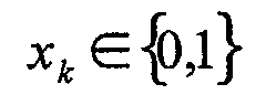
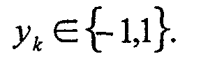
- Thus the actual mapping is '1' → '-1' and '0' → '1'.
- There are only four different values per k in total the
γ can take, one for every assumptionThe code-structure alone determines, which of them is assigned to which transition. After skipping constant factors and making additional algebraic transformations we get :

- This simplifies the implementation significantly, as only two terms have to be computed from the channel and a priori data. One term can be dropped completely and the last one be computed from the first two. The scaling factor 4Es / N 0 is multiplied externally by usage of a working point.
- 5.2 The combined decoder CTD according to this embodiment, as illustrated on figure 13, comprises Turbo-code decoding means TCDCM for performing Turbo-code decoding, and convolutional code processing means CCDCM for performing convolutional code.
- Turbo-code and convolutional code decoding means comprise common processing means CCPR implementing MAP algorithm and having a first configuration dedicated to Turbo-code decoding and a second configuration dedicated to convolutional code decoding. Said common processing means CCPR or MAP unit form a Soft-in-Soft-out unit (SISO unit) on which MAP1 and MAP2 operations are done serially for turbo decoding, until a stopping criterion is fullfilled.
- Further to these common processing means, the Turbo-code decoding means TCDM comprises conventional interleaving means IL.
- Moreover, the combined decoder CTD comprises metrics memory means referenced as TC alpha-RAM for storing forward state metrics associated to the states of a first trellis (8 states here), said forward state metrics being delivered by the processing means CCPR in its first configuration (Turbo decoding).
- Input/output memory means referenced as CC I/O RAMs are provided for storing input and output data delivered to and by the processing means CCPR in its second configuration, i.e. for CC decoding.
- At last, adaptable memory means ADMM are used for storing input and output data delivered to and by said processing means CCPR in its first configuration (Turbo-code decoding), and for storing forward state metrics associated to the states of a second trellis (256 states here) and delivered by said processing means CCPR in its second configuration (convolutional code decoding).
- Control means CDRLM configurate said common processing means CCPR in its first or second configuration depending on the kind of code, and memory control means CTMM address differently said adaptable memory means ADMM depending on the configuration of said common processing means CCPR.
- Figure 14 illustrates more in detail thus internal structures of the common processing means CCPR.
- The processing means CCPR comprise essentially three major of calculation unit, i.e.,
the BM unit that calculates the branch metrics BM and controls the complete I/O RAMs and alpha RAM ;
the state metric unit which calculates 8 state metrics SM in parallel with 8 add-compare-select (ACS) units ;
the LLR unit, which calculates the LLRs in a pipelined manner. - The input RAMs consist in three RAMs referenced as G0_RAM G1_RAM and G2_RAM according to the respective CC input data. Output RAM is CCLLR_RAM. The RAM-sizes are 512*6 bits.
- The alpha state metric RAM for TC decoding is a dedicated 64*88bit RAM (alpha_RAM).
- The adaptable memory means ADMM is used either for storing input and output data for Turbo-code decoding or for storing forward state metrics in the convolutional code decoding.
- And, as shown on figure 15, these adaptable memory means comprises a lot of elementary memories as well as an additional memory means Add.
- More precisely, in the present application, the Turbo-code decoding means are adapted to receive successive sequences of N1 symbols (N1=5120) of b1 bits (b1=6). The input and output data delivered to and by the processing means CCPR in its first configuration (Turbo decoding) comprises for each received sequence, g different blocs of N1 words of b1 bits. Here, g=4 and these g blocs are
the systematic input data X,
the parity input data Y1,
the interleaved parity input data Y2 and,
the decisions of the decoding, as output data. - The forward state metrics to be stored in the adaptable memory means (when convolutional code decoding) is a bloc of N2 words (N2=1728) of b2 bits, b2 being here greater than b1. Generally, the product N2 times b2 is equal to the product of W (windowsize) with the number of states of the trellis and, with the number of bits for each state. In the present case, W is equal to 54 or the convolutional code, 64 for the Turbo-code. The number of states is equal to 8 for the Turbo-code and to 256 for the convolutional code. And, the number of bits for each state is equal to 11.
- Accordingly, N2 is equal to 1728 whereas b2 is equal to 88.
- Thus, as shown on figure 8, the main memory means of the adaptable memory means ADDM comprises 4 groups of p (p=3) elementary memories respectively dedicated to the g blocs of N1 words. And, each elementary memory is adapted to store N2 words of b1 bits.
- The additional memory Add is adapted to store 1728 words of 16 bits.
- And, generally speaking, the memory control means address the adaptable memory means ADMM in said first configuration (Turbo-code decoding) such that each bloc of 5120 words of 6 bits is written in or read from its dedicated group of 3 elementary memories.
- Further, said memory control means address said adaptable memory means ADMM in said second configuration (convolutional code decoding) such that the twelve elementary words of said forward state metrics are respectively stored in the twelve elementary memories of the main memory means at the same address, whereas the additional elementary word of the forward state metrics (the 16 other bits) is stored in the additional memory means at the same address.
- In other words, for CC decoding each of the I/O RAMs of the TC is split into 3 separate RAMs. These RAMs are the concatenated to form the required bitwidth for the storage of 8 state metrics in parallel. We need 88 bits (8* 11 bit), the I/O RAMs are 6 bit wide so we get 4*3*6 bit=72 bit. Therefore we need an additional 16bit RAM to form the CC alpha RAM. This RAM sharing enables us to get a sufficient windowsize for CC decoding.
- As shown on figure 15, the naming conventions are as follows:
- The systematic input data is stored in X_RAM1, X_RAM2, X_RAM3,
the parity input data is stored in Y1_RAM1, Y1_RAM2, Y1_RAM3, and
the interleaved parity input data is stored in Y2_RAM1, Y2_RAM2, Y2_RAM3. - The TC output RAMs are LLR_RAM1, LLR_RAM2 and LLR_RAM3. The MSB represents the output hard decision, whereas the LSB represent the extrinsic information/LLR soft decision (depending on actual decoding progress). This enables a stopping of the decoding after MAP1 CRC check.
- Because the RAMs are split into three, an appropriate address transformation is done to map the address space 0-5119 to three times 0-1727. This value is rounded up to the minimum feasible RAM. Only the actual needed RAMs are activated, all others are deselected.
- The common processing means comprises a branch metric unit for calculating in each first and second configurations the branch metrics associated to the branches of the corresponding trellis (see eq. 2.17 for turbo code).
- The transfer of TC input data samples to the CTD decoder is done in the following order :
X 1,Y 1 / 1,Y 2 / 1,X 2,Y 1 / 2,Y 2 / 2,........X Bi ,Y 2 / Bi,TailBits
Bi is the number of bits in the i-th code block.
The storage of the tail bits has to be considered, the transmitted bits for the trellis termination are:
x K+1, z K+1, x K+2, z K+2, x K+3, z K+3, x' K+1, z' K+1, x' K+2, z' K+2, x' K+3, z' K+3; where Y1= z, Y2= z' and x'=XSecond encoder, K=block length.
The parity data RAMs Y1 and Y2 are filled sequentially, the respective three tailbits are just appended. The systematic data RAM X is also filled sequentially, because there are six tailbits in total, the tailbits for the first encoder are appended first, then the tailbits for the second encoder follow. - The input sequence for CC decoding is simpler, because there is only one tail sequence. The tailbits are just appended to the respective RAM.
- The different steps of the windowing scheme can be divided into further sub-steps. The calculation of the branch metrics is the prerequisite for the calculation of the state metrics. The memory control mean therefore addresses the input RAMs to calculate the respective branch metrics. We use the optimized MAP calculation scheme proposed above. The used naming convention is based on the binary representation of the pair [systematic/parity information] ∈{0,1} resp. [G0/G1], [G0/G1/G2]. X, Y, LLR, G0, G1, G2 represent the individual data stored in this RAMs (e.g. the content of the LLR-RAM is the extrinsic information).
- Turbo Code:
- branch0 = 0
- branch1 = Y
- branch2 = X + LLR
- branch3 = X + Y + LLR
- Convolutional Code, rate 1/2:
- branch0 = 0
- branch1 = G1
- branch2 = G0
- branch3 = G1 + G0
- Convolutional Code, rate 1/3:
- branch0 = 0
- branch1 = G2
- branch2 = G1
- branch3 = G1 + G2
- branch4 = G0
- branch5 = G0 + G2
- branch6 = G0 + G1
- branch7 = G0 + G1 + G2
-
- The branch metric calculation is very simple, two additions for TC and one resp. four additions (calculation of branch7 reuses a previously addition, e.g. G0+G1) for CC. In case of TC we have to use interleaved data during MAP2 operation. Therefore the BM unit interacts with the external interleaver to fetch the appropriate addresses. In order to avoid data collisions during forward and backward TC recursion, a dedicated LLR-cache is needed as well as a dedicated LLR-register.
- Turning now to the calculation of the state metrics, the common processing means comprises a configurable state metrics unit SM.
- As shown on figures 14, 15, and 16, the configurable state metrics units SM comprises
- an architecture of 8 parallel ACS (Add, Compare, Select) units for calculating in each configuration 8 forward state metrics,
- auxiliary memory means (AXMM) for temporarily storing the calculated forward state metrics for a recursive calculation, and
- auxiliary control means for controlling the storage of the metrics in said auxiliary memory means depending on the configuration of said common processing means.
- More precisely, the ACS architecture illustrated on figure 16, calculates eight state metrics in parallel out of the branch metrics and the previous state metrics according to equations 2.10 and 2.11. This is done with 8 ACS (Add, Compare, Select) units based on a modmin-procedure (the MODMIN blocs perform the min* operator).
- This ACS architecture is used for forward as well as for backward recursion for both Turbo code and Convolutional code. Because of the different trellis diagrams, the flexibility is achieved with multiplexers for the incoming branch metrics (bmux) and state metrics (smux). These multiplexers are controlled externally as explained thereafter.
- The eight ACS units need sixteen branch metric + state metric sums, therefore sixteen bmux multiplexers are provided. Each of these bmux multiplexers can select among eight branch metrics (because CC rate 1/3 needs eight different branch metrics in total). However, because of a particular state metric distribution not sixteen but only twelve smux state metric multiplexers are needed. Furthermore this state metric distribution leads to only 2:1 smux multiplexers, because the setting is valid for either CC forward recursion/TC backward recursion or CC backward/TC forward recursion. There is no additional multiplexing of the calculated state metrics. In case of forward recursion, the new state metrics are always in ascending order. Figure 16 shows the general architecture of the acs architecture. Sm1-sm8 denote the 8 parallel input state metrics at one timestep, bm0-bm7 denote the up to 8 different branch metrics. The smux setting for TC forward/CC backward is marked bold.The output of this unit are the new state metrics as well as the LLR-metrics (βstate metric + branch metric) for the LLR calculation.
- The multiplexer of the state metrics unit are controlled by a specific machine, not shown for reason of simplification.
- The state metric multiplexer smux controlling is very simple. There are only two different settings, either for TC forward recursion/CC backward recursion or for TC backward recursion/CC forward recursion. The controlling of the branch metric multiplexer bmux is more complex and done in the FSM. Each sequence (32 steps) depends on the chosen rate as well as on the actual operation (forward recursion or backward recursion).
- CC rate 1/2 forward recursion
There are 4 different sets of bmux settings, denoted A,B,C,DThe forward sequence is
AABBCCDDAABBCCDDCCDDAABBCCDDAABB - CC rate 1/2 backward recursion
There are 4 different sets of bmux settings, denoted A,B,C,DThe backward sequence is
AABBCCDDAABBCCDDBBAADDCCBBAADDCC - CC rate 1/3 forward recursion
There are 8 different sets of bmux settings, denoted
A,B,C,D,E,F,G,HThe forward sequence is
ABCDEFGHFEHGBADCHGFEDCBACDABGHEF - CC rate 1/3 backward recursion
There are 8 different sets of bmux settings, denoted
A,B,C,D,E,F,G,HThe backward sequence is
ABCDEFGHFEHGBADCDCBAHGFEGHEFCDA - The LLR unit calculates the LLR (see eq. 2.12 for turbo code). This is done in a pipeline for the TC decoder consisting of three modmin stages with registers between stage one and stage two see Figure17. Input to the first stage are the sums alpha state metric from the alpha RAM + LLRsum (= branch metric + beta state metric) from the SM unit. This values are also registered, thus resulting in a total pipeline depth of four. The upper modmin-tree calculates the minimum of all states reached by input '1' (LLR1), the lower one the minimum reached by input '0' (LLR0).
- Once the LLR calculation starts, new values are present at the inputs every clock cycle. The control is very simple and done by a simple shifting of a data valid flag through a 4 stage Flip-Flop pipeline.
- Parts of the LLR calculation for TC are reused for Convolutional decoding, see figure 17 (not shown are the multiplexer for the input values and the adder for calculating the sums).
- More precisely, all the architecture shown on figure 17 is used for Turbo decoding whereas only the upper and lower parts thereof are used for convolutional code decoding.
- Since the encoding of the Convolutional Code is done with a NSC, the input '0' resp. '1' determines the state number.
- Therefore we don't need the branch metrics, which simplifies the calculation to only four modmin units in the first stage. The upper two modmin units calculate the minimum of the four state metric sums reached by input '1' (onestates), the lower two the minimum of input '0' (zerostates). Therefore the inputs are the alpha state metrics from the alpha-RAM and the beta metrics from the AXMM memory.
- Because we don't calculate all 256 states at once we need a loopback to determine the appropriate minimums. This is additional hardware compared to the Turbo decoder part and situated after stage 2. The controlling is quite simple and realized with a FSM. This can be best expressed when looking at the feedback unit for the onestates. The first minimum is stored in the lower register, the second one in the upper register. All following minima are stored in the lower register, the resulting minimum always in the upper register. The LLR_valid flag is also generated by the FSM.
- At last, the combined decoder according to the invention comprises a global control unit which controls the decoding process on MAP level. Because TC decoding is done in an iterative matter, the number of iterations depends on the actual decoding status. Therefore after each MAP operation a stopping criterion is checked. This stopping criterion can either be the selected total number of half-iterations, a correctly detected CRC-sum (only after MAP1) or an early detection of undecodable blocks based on the mean value criterion. The particular decoding steps for TC are shown in figure 18. In case of CC decoding only one MAP1 operation is needed.
- Furthermore the global control unit controls the handshake mode. This handshake mode allows step-by-step execution of the decoding steps and on-demand memory flush.
Claims (20)
- Method of blindly detecting a transport format of an incident convolutional encoded signal, said transport format being ex ante unknown and belonging to a set of MF predetermined reference transport formats, said signal comprising a data block having an ex ante unknown number of bits corresponding to said ex ante unknown transport format, and a cyclic redundancy check (CRC) field containing a transmitted CRC word, said method comprising decoding said signal using a Maximum-a-Posteriori algorithm, said decoding step including decoding said signal considering respectively the MF possible reference formats and respectively delivering MF corresponding groups of soft output information, calculating from each group of soft output information a calculated CRC word and comparing said calculated CRC word with said transmitted CRC word, selecting all the groups for which said calculated CRC word is equal to said transmitted CRC word, and selecting the actual transport format of the encoded signal from at least one soft output information among the last ones of each selected group.
- Method according to claim 1, characterized by the fact that said the actual transport format of the encoded signal is selected from the last soft output information of each selected group.
- Method according to claim 2, characterized by the fact that the actual transport format is the reference format having the greatest last soft output information.
- Method according to any one of the preceding claims, characterized by the fact that said decoding step comprises calculating states metrics, by the fact that all the data blocks are decoded in parallel window-by-window on sliding windows having a predetermined size, and by the fact that at least some of the states metrics calculated on a window are valid for all the data blocks.
- Method according to claim 4, characterized by the fact that said decoding step comprises for each window calculating forward state metrics during a forward recursion, performing a backward acquisition having a predetermined acquisition length, calculating backward state metrics during a backward recursion and calculating soft output information in the reverse order, by the fact that for each window only one forward recursion is performed which is valid for all the transport formats.
- Method according to claim 5, characterized by the fact that the first window processing including forward recursion, backward acquisition, backward recursion and soft output calculation, is completely valid for all data blocks having a size larger than the sum of the window size and the acquisition length.
- Convolutional code decoder, comprising input means for receiving an convolutional encoded signal having an ex ante unknown transport format belonging to a set of MF predetermined reference transport formats, said signal comprising a data block having an ex ante unknown number of bits corresponding to said ex ante unknown transport format, and a cyclic redundancy check (CRC) field containing a transmitted CRC word, convolutional code decoding means implementing a Maximum-a-Posteriori algorithm for decoding successively said signal by considering respectively successively the MF possible reference formats and comprising a Log-Likelihood-Ratio unit for successively respectively delivering MF corresponding groups of soft output information, blind transport format detection means comprising a cyclic redundancy check unit for calculating from each group of soft output information a calculated CRC word and comparison means for comparing said calculated CRC word with said transmitted CRC word, first selection means for selecting all the groups for which said calculated CRC word is equal to said transmitted CRC word, and second selection means for selecting the actual transport format of the encoded signal from at least one soft output information among the last ones of each selected group.
- Convolutional code decoder according to claim 7, characterized by the fact that said second selection means are adapted to select the actual transport format of the encoded signal from the last soft output information of each selected group.
- Convolutional code decoder according to claim 8, characterized by the fact that the actual transport format is the reference format having the greatest last soft output information.
- Convolutional code decoder according to any one of claims 7 to 9, characterized by the fact that said convolutional code decoding means are adapted to calculate states metrics, by the fact that all the data blocks are decoded in parallel window-by-window on sliding windows having a predetermined size, and by the fact that at least some of the states metrics calculated on a window are valid for all the data blocks.
- Convolutional code decoder according to claim 10, characterized by the fact that said convolutional code decoding means are adapted for each window, to calculate forward state metrics during a forward recursion, to perform a backward acquisition having a predetermined acquisition length, to calculate backward state metrics during a backward recursion, by the fact that for each window only one forward recursion is performed which is valid for all the transport formats.
- Convolutional code decoder according to claim 11, characterized by the fact that the first window processing including forward recursion, backward acquisition, backward recursion and soft output calculation, is completely valid for all data blocks having a size larger than the sum of the window size and the acquisition length.
- Convolutional code decoder according to any one of claim 7 to 12, characterized by the fact it is a combined Turbo-code/convolutional code decoder further comprising Turbo-code decoding means (TCDCM) for performing turbo-code decoding.
- Convolutional code decoder according to claim 13, characterized by the fact that said Turbo-code and convolutional code decoding means comprising common processing means (CCPR) having a first configuration dedicated to Turbo-code decoding and a second configuration dedicated to convolutional code decoding, and by the fact that said decoder further comprises :metrics memory means (TCα-RAM) for storing state metrics associated to the states of a first trellis and delivered by said processing means in its first configuration,input/output memory means (CC I/O RAMs) for storing input and output data delivered to and by said processing means in its second configuration,adaptable memory means (ADMM) for storing input and output data delivered to and by said processing means in its first configuration, and for storing state metrics associated to the states of a second trellis and delivered by said processing means in its second configuration,control means (CTRLM) for configurating said common processing means in its first or second configuration depending on the kind of code, andmemory control means (CTMM) for addressing differently said adaptable memory means depending on the configuration of said common processing means.
- Convolutional code decoder according to any one of claims 7 to 14, characterized by the fact that said common processing means (CCPR) implements a Maximum-A-Posteriori (MAP) algorithm.
- Convolutional code decoder according to claim 15, characterized by the fact that the MAP algorithm implemented is a so-called LogMAP algorithm or a so-called MaxLogMAP algorithm.
- Convolutional code decoder according to any one of claims 7 to 16, characterized by the fact it is realized by an integrated circuit.
- Terminal of a wireless communication system, including a decoder according to any one of claims 7 to 17.
- Terminal according to claim 18, characterized by the fact it forms a cellular phone.
- Terminal according to claim 18, characterized by the fact it forms a base station.
Priority Applications (3)
| Application Number | Priority Date | Filing Date | Title |
|---|---|---|---|
| EP20030290993 EP1471677A1 (en) | 2003-04-23 | 2003-04-23 | Method of blindly detecting a transport format of an incident convolutional encoded signal, and corresponding convolutional code decoder |
| JP2004106933A JP2004343716A (en) | 2003-04-23 | 2004-03-31 | Method for blind detection of transmission format of convolutionally encoded signal and decoder |
| US10/830,420 US20050091566A1 (en) | 2003-04-23 | 2004-04-22 | Method of blindly detecting a transport format of an incident convolutional encoded signal, and corresponding convolutional code decoder |
Applications Claiming Priority (1)
| Application Number | Priority Date | Filing Date | Title |
|---|---|---|---|
| EP20030290993 EP1471677A1 (en) | 2003-04-23 | 2003-04-23 | Method of blindly detecting a transport format of an incident convolutional encoded signal, and corresponding convolutional code decoder |
Publications (1)
| Publication Number | Publication Date |
|---|---|
| EP1471677A1 true EP1471677A1 (en) | 2004-10-27 |
Family
ID=32946957
Family Applications (1)
| Application Number | Title | Priority Date | Filing Date |
|---|---|---|---|
| EP20030290993 Withdrawn EP1471677A1 (en) | 2003-04-23 | 2003-04-23 | Method of blindly detecting a transport format of an incident convolutional encoded signal, and corresponding convolutional code decoder |
Country Status (3)
| Country | Link |
|---|---|
| US (1) | US20050091566A1 (en) |
| EP (1) | EP1471677A1 (en) |
| JP (1) | JP2004343716A (en) |
Cited By (4)
| Publication number | Priority date | Publication date | Assignee | Title |
|---|---|---|---|---|
| WO2005060107A1 (en) * | 2003-12-11 | 2005-06-30 | Freescale Semiconductor, Inc. | A decoder |
| GB2425026A (en) * | 2005-04-08 | 2006-10-11 | Ind Tech Res Inst | Cyclic Redundancy Check modification for length detection of message with convolutional protection |
| FR2962615A1 (en) * | 2010-07-06 | 2012-01-13 | Univ Bretagne Occidentale | METHOD AND APPARATUS FOR BINARY TRAIN ANALYSIS AND BLIND RECONSTRUCTION OF ERROR CORRECTING CODES |
| CN103905065A (en) * | 2012-12-28 | 2014-07-02 | 联芯科技有限公司 | Convolutional code decoding method and device |
Families Citing this family (14)
| Publication number | Priority date | Publication date | Assignee | Title |
|---|---|---|---|---|
| US7853859B2 (en) * | 2004-01-23 | 2010-12-14 | Broadcom Corporation | Convolutional coding method for multi-band communications |
| WO2006106377A1 (en) * | 2005-04-07 | 2006-10-12 | Nokia Corporation | Blind transport format detection based on decoder metric |
| JP4436315B2 (en) * | 2005-12-26 | 2010-03-24 | 京セラ株式会社 | Convolutional encoder, communication apparatus, and convolutional encoding method |
| WO2009063328A2 (en) | 2007-10-17 | 2009-05-22 | Marvell World Trade Ltd. | State metrics memory reduction in a turbo decoder implementation |
| US20120028684A1 (en) * | 2008-01-31 | 2012-02-02 | Panasonic Corporation | Radio communication device and error correction/encoding method |
| GB0915135D0 (en) * | 2009-08-28 | 2009-10-07 | Icera Inc | Decoding signals received over a noisy channel |
| CN101667840B (en) * | 2009-09-08 | 2012-12-12 | 华为技术有限公司 | Method and device for tail biting decoding |
| US8861653B2 (en) * | 2012-05-04 | 2014-10-14 | Qualcomm Incorporated | Devices and methods for obtaining and using a priori information in decoding convolutional coded data |
| US8787506B2 (en) | 2012-05-04 | 2014-07-22 | Qualcomm Incorporated | Decoders and methods for decoding convolutional coded data |
| TWI520502B (en) * | 2012-11-23 | 2016-02-01 | 晨星半導體股份有限公司 | Cyclotron deinterlacing device and cyclotron deinterlacing method |
| US9213602B1 (en) * | 2014-06-23 | 2015-12-15 | Seagate Technology Llc | Write mapping to mitigate hard errors via soft-decision decoding |
| US10341471B2 (en) * | 2016-12-29 | 2019-07-02 | Onward Security Corporation | Packet analysis apparatus, method, and non-transitory computer readable medium thereof |
| CN110289936B (en) * | 2019-07-01 | 2020-05-12 | 北京理工大学 | A 5G downlink control channel blind detection method based on weight ranking |
| CN120498600B (en) * | 2025-07-15 | 2025-10-03 | 成都市四度空间科技有限公司 | Non-system convolutional code parameter blind identification method, medium and program product |
Citations (5)
| Publication number | Priority date | Publication date | Assignee | Title |
|---|---|---|---|---|
| US20010046269A1 (en) * | 2000-01-31 | 2001-11-29 | Alan Gatherer | MAP decoding with parallelized sliding window processing |
| WO2002007453A2 (en) * | 2000-07-17 | 2002-01-24 | Motorola, Inc. | Improved sliding window turbo decoder for convolutional codes |
| EP1204210A1 (en) * | 2000-09-18 | 2002-05-08 | Lucent Technologies Inc. | Architecture for a communications device |
| EP1207659A2 (en) * | 2000-11-17 | 2002-05-22 | NTT DoCoMo, Inc. | Data transmission method, data transmission system, transmitter and receiver |
| US20020108090A1 (en) * | 2001-02-05 | 2002-08-08 | Cute Ltd. | Blind transport format detection of turbo-coded data |
Family Cites Families (6)
| Publication number | Priority date | Publication date | Assignee | Title |
|---|---|---|---|---|
| US6442747B1 (en) * | 2000-05-10 | 2002-08-27 | 3Com Corporation | Method of synthesizing a cycle redundancy code generator circuit using hardware description language |
| US6452979B1 (en) * | 2000-09-06 | 2002-09-17 | Motorola, Inc. | Soft output decoder for convolutional codes |
| JP3399923B2 (en) * | 2000-11-29 | 2003-04-28 | 松下電器産業株式会社 | Communication terminal apparatus and decoding method in communication terminal apparatus |
| US6845482B2 (en) * | 2001-02-28 | 2005-01-18 | Qualcomm Incorporated | Interleaver for turbo decoder |
| US7072926B2 (en) * | 2001-06-08 | 2006-07-04 | Texas Instruments Incorporated | Blind transport format detection system and method with logarithm approximation for reliability figure |
| KR100421765B1 (en) * | 2001-12-06 | 2004-03-11 | 한국전자통신연구원 | Method for determining a transmission rate of variable number of bits in an asynchronous mobile telecommunication system and apparatus thereof |
-
2003
- 2003-04-23 EP EP20030290993 patent/EP1471677A1/en not_active Withdrawn
-
2004
- 2004-03-31 JP JP2004106933A patent/JP2004343716A/en active Pending
- 2004-04-22 US US10/830,420 patent/US20050091566A1/en not_active Abandoned
Patent Citations (5)
| Publication number | Priority date | Publication date | Assignee | Title |
|---|---|---|---|---|
| US20010046269A1 (en) * | 2000-01-31 | 2001-11-29 | Alan Gatherer | MAP decoding with parallelized sliding window processing |
| WO2002007453A2 (en) * | 2000-07-17 | 2002-01-24 | Motorola, Inc. | Improved sliding window turbo decoder for convolutional codes |
| EP1204210A1 (en) * | 2000-09-18 | 2002-05-08 | Lucent Technologies Inc. | Architecture for a communications device |
| EP1207659A2 (en) * | 2000-11-17 | 2002-05-22 | NTT DoCoMo, Inc. | Data transmission method, data transmission system, transmitter and receiver |
| US20020108090A1 (en) * | 2001-02-05 | 2002-08-08 | Cute Ltd. | Blind transport format detection of turbo-coded data |
Non-Patent Citations (1)
| Title |
|---|
| PIETROBON S S: "IMPLEMENTATION AND PERFORMANCE OF A TURBO/MAP DECODER", INTERNATIONAL JOURNAL OF SATELLITE COMMUNICATIONS, JOHN WILEY AND SONS, US, vol. 16, no. 1, 1998, pages 23 - 46, XP000856961, ISSN: 0737-2884 * |
Cited By (8)
| Publication number | Priority date | Publication date | Assignee | Title |
|---|---|---|---|---|
| WO2005060107A1 (en) * | 2003-12-11 | 2005-06-30 | Freescale Semiconductor, Inc. | A decoder |
| US7652597B2 (en) | 2003-12-11 | 2010-01-26 | Freescale Semiconductor, Inc. | Multimode decoder |
| GB2425026A (en) * | 2005-04-08 | 2006-10-11 | Ind Tech Res Inst | Cyclic Redundancy Check modification for length detection of message with convolutional protection |
| GB2425026B (en) * | 2005-04-08 | 2007-12-19 | Ind Tech Res Inst | Cyclic redundancy check modification for lenght detection of message with convolutional protection |
| FR2962615A1 (en) * | 2010-07-06 | 2012-01-13 | Univ Bretagne Occidentale | METHOD AND APPARATUS FOR BINARY TRAIN ANALYSIS AND BLIND RECONSTRUCTION OF ERROR CORRECTING CODES |
| US9083381B2 (en) | 2010-07-06 | 2015-07-14 | Universite De Bretagne Occidentale | Method of determining at least one parameter of an error-correcting code implemented on transmission, corresponding device and computer program |
| CN103905065A (en) * | 2012-12-28 | 2014-07-02 | 联芯科技有限公司 | Convolutional code decoding method and device |
| CN103905065B (en) * | 2012-12-28 | 2017-06-13 | 联芯科技有限公司 | A kind of coding method of convolution code and device |
Also Published As
| Publication number | Publication date |
|---|---|
| JP2004343716A (en) | 2004-12-02 |
| US20050091566A1 (en) | 2005-04-28 |
Similar Documents
| Publication | Publication Date | Title |
|---|---|---|
| US7191377B2 (en) | Combined turbo-code/convolutional code decoder, in particular for mobile radio systems | |
| US7209527B2 (en) | Turbo decoder employing max and max* map decoding | |
| AU762877B2 (en) | Component decoder and method thereof in mobile communication system | |
| US20050091566A1 (en) | Method of blindly detecting a transport format of an incident convolutional encoded signal, and corresponding convolutional code decoder | |
| US6799295B2 (en) | High speed turbo codes decoder for 3G using pipelined SISO log-map decoders architecture | |
| KR100369423B1 (en) | Soft output decoder for convolutional codes | |
| KR20010072498A (en) | Partitioned deinterleaver memory for map decoder | |
| WO2002007453A2 (en) | Improved sliding window turbo decoder for convolutional codes | |
| KR20080098391A (en) | MAP decoder with bidirectional sliding window architecture | |
| US8112698B2 (en) | High speed turbo codes decoder for 3G using pipelined SISO Log-MAP decoders architecture | |
| WO2002021701A1 (en) | Soft output decoder for convolutional codes | |
| US6807239B2 (en) | Soft-in soft-out decoder used for an iterative error correction decoder | |
| US20130007568A1 (en) | Error correcting code decoding device, error correcting code decoding method and error correcting code decoding program | |
| WO2011023782A1 (en) | Iterative decoding of signals received over a noisy channel using forward and backward recursions with warm-up initialization | |
| KR100390416B1 (en) | Method for decoding Turbo | |
| JP2001267936A (en) | Soft decision output decoder for convolution coding | |
| EP1128560B1 (en) | Apparatus and method for performing SISO decoding | |
| EP1414158A1 (en) | Method of decoding an incident turbo-code encoded signal in a receiver, and corresponding receiver, in particular for mobile radio systems | |
| KR101051933B1 (en) | Metric Computation for Map Decoding Using Trellis' Butterfly Structure | |
| US20030093753A1 (en) | Error correction code decoding device | |
| US7096410B2 (en) | Turbo-code decoding using variably set learning interval and sliding window | |
| US20040083252A1 (en) | Turbo decoder | |
| Kreiselmaier et al. | Combined turbo and convolutional decoder architecture for UMTS wireless applications | |
| WO2000057560A2 (en) | Improved turbo decoder 1 | |
| US20070157063A1 (en) | Method for iterative decoding in a digital system and apparatus implementing the method |
Legal Events
| Date | Code | Title | Description |
|---|---|---|---|
| PUAI | Public reference made under article 153(3) epc to a published international application that has entered the european phase |
Free format text: ORIGINAL CODE: 0009012 |
|
| AK | Designated contracting states |
Kind code of ref document: A1 Designated state(s): AT BE BG CH CY CZ DE DK EE ES FI FR GB GR HU IE IT LI LU MC NL PT RO SE SI SK TR |
|
| AX | Request for extension of the european patent |
Extension state: AL LT LV MK |
|
| 17P | Request for examination filed |
Effective date: 20050405 |
|
| AKX | Designation fees paid |
Designated state(s): DE FR GB IT |
|
| STAA | Information on the status of an ep patent application or granted ep patent |
Free format text: STATUS: THE APPLICATION IS DEEMED TO BE WITHDRAWN |
|
| 18D | Application deemed to be withdrawn |
Effective date: 20081107 |