EP1471624A2 - Method of molding resin to protect a resolver winding - Google Patents
Method of molding resin to protect a resolver winding Download PDFInfo
- Publication number
- EP1471624A2 EP1471624A2 EP04009156A EP04009156A EP1471624A2 EP 1471624 A2 EP1471624 A2 EP 1471624A2 EP 04009156 A EP04009156 A EP 04009156A EP 04009156 A EP04009156 A EP 04009156A EP 1471624 A2 EP1471624 A2 EP 1471624A2
- Authority
- EP
- European Patent Office
- Prior art keywords
- mold member
- stack
- resolver
- winding
- stator
- Prior art date
- Legal status (The legal status is an assumption and is not a legal conclusion. Google has not performed a legal analysis and makes no representation as to the accuracy of the status listed.)
- Granted
Links
Images


Classifications
-
- H—ELECTRICITY
- H02—GENERATION; CONVERSION OR DISTRIBUTION OF ELECTRIC POWER
- H02K—DYNAMO-ELECTRIC MACHINES
- H02K15/00—Processes or apparatus specially adapted for manufacturing, assembling, maintaining or repairing of dynamo-electric machines
- H02K15/12—Impregnating, moulding insulation, heating or drying of windings, stators, rotors or machines
-
- H—ELECTRICITY
- H01—ELECTRIC ELEMENTS
- H01F—MAGNETS; INDUCTANCES; TRANSFORMERS; SELECTION OF MATERIALS FOR THEIR MAGNETIC PROPERTIES
- H01F41/00—Apparatus or processes specially adapted for manufacturing or assembling magnets, inductances or transformers; Apparatus or processes specially adapted for manufacturing materials characterised by their magnetic properties
- H01F41/02—Apparatus or processes specially adapted for manufacturing or assembling magnets, inductances or transformers; Apparatus or processes specially adapted for manufacturing materials characterised by their magnetic properties for manufacturing cores, coils, or magnets
- H01F41/04—Apparatus or processes specially adapted for manufacturing or assembling magnets, inductances or transformers; Apparatus or processes specially adapted for manufacturing materials characterised by their magnetic properties for manufacturing cores, coils, or magnets for manufacturing coils
- H01F41/12—Insulating of windings
- H01F41/127—Encapsulating or impregnating
-
- H—ELECTRICITY
- H02—GENERATION; CONVERSION OR DISTRIBUTION OF ELECTRIC POWER
- H02K—DYNAMO-ELECTRIC MACHINES
- H02K3/00—Details of windings
- H02K3/46—Fastening of windings on the stator or rotor structure
- H02K3/52—Fastening salient pole windings or connections thereto
- H02K3/521—Fastening salient pole windings or connections thereto applicable to stators only
- H02K3/522—Fastening salient pole windings or connections thereto applicable to stators only for generally annular cores with salient poles
-
- H—ELECTRICITY
- H02—GENERATION; CONVERSION OR DISTRIBUTION OF ELECTRIC POWER
- H02K—DYNAMO-ELECTRIC MACHINES
- H02K24/00—Machines adapted for the instantaneous transmission or reception of the angular displacement of rotating parts, e.g. synchro, selsyn
-
- Y—GENERAL TAGGING OF NEW TECHNOLOGICAL DEVELOPMENTS; GENERAL TAGGING OF CROSS-SECTIONAL TECHNOLOGIES SPANNING OVER SEVERAL SECTIONS OF THE IPC; TECHNICAL SUBJECTS COVERED BY FORMER USPC CROSS-REFERENCE ART COLLECTIONS [XRACs] AND DIGESTS
- Y10—TECHNICAL SUBJECTS COVERED BY FORMER USPC
- Y10T—TECHNICAL SUBJECTS COVERED BY FORMER US CLASSIFICATION
- Y10T29/00—Metal working
- Y10T29/49—Method of mechanical manufacture
- Y10T29/49002—Electrical device making
- Y10T29/49009—Dynamoelectric machine
-
- Y—GENERAL TAGGING OF NEW TECHNOLOGICAL DEVELOPMENTS; GENERAL TAGGING OF CROSS-SECTIONAL TECHNOLOGIES SPANNING OVER SEVERAL SECTIONS OF THE IPC; TECHNICAL SUBJECTS COVERED BY FORMER USPC CROSS-REFERENCE ART COLLECTIONS [XRACs] AND DIGESTS
- Y10—TECHNICAL SUBJECTS COVERED BY FORMER USPC
- Y10T—TECHNICAL SUBJECTS COVERED BY FORMER US CLASSIFICATION
- Y10T29/00—Metal working
- Y10T29/49—Method of mechanical manufacture
- Y10T29/49002—Electrical device making
- Y10T29/49009—Dynamoelectric machine
- Y10T29/49011—Commutator or slip ring assembly
-
- Y—GENERAL TAGGING OF NEW TECHNOLOGICAL DEVELOPMENTS; GENERAL TAGGING OF CROSS-SECTIONAL TECHNOLOGIES SPANNING OVER SEVERAL SECTIONS OF THE IPC; TECHNICAL SUBJECTS COVERED BY FORMER USPC CROSS-REFERENCE ART COLLECTIONS [XRACs] AND DIGESTS
- Y10—TECHNICAL SUBJECTS COVERED BY FORMER USPC
- Y10T—TECHNICAL SUBJECTS COVERED BY FORMER US CLASSIFICATION
- Y10T29/00—Metal working
- Y10T29/49—Method of mechanical manufacture
- Y10T29/49002—Electrical device making
- Y10T29/49009—Dynamoelectric machine
- Y10T29/49012—Rotor
Definitions
- the present invention relates to a resin molding method for protecting the winding of a resolver.
- the resin is to protect the winding, which is coiled around multiple magnetic poles of a stack of the resolver.
- the resolver includes a rotatable, assembled rotor stack and a stator stack.
- the stator stack includes a coiled excitation winding and an output winding wound around multiple magnetic poles.
- the winding portion of the stator stack is typically coated with resin material such as a varnish to fix the windings and to improve the insulation properties.
- a prior art molding method at least the winding of the stack is molded by injecting a fused resin molding material into a space formed between a top mold and a bottom mold member, while the annular stack of the resolver, including a coiled winding, is sandwiched between the top mold and bottom mold member.
- a fused resin molding material for example, a fused resin molding material
- the annular stack of the resolver including a coiled winding
- the stator stack of the resolver is structured such that thin silicon steel plates, which are press punched into an annular shape, are laminated and then adhered or crimped. There is non-uniformity in the thickness of the silicon steel plate, and this non-uniformity is accumulated across a number of the silicon steel plates. Therefore the thickness of the stator stack is not uniform. There is variation of 8 to 10% in the thickness of a single silicon steel plate. A variation equal to the number of silicon steel plates multiplied by 8 to 10% is produced in the thickness of the stator stack. Therefore, gaps are generated between the stator stack and the mold during the resin molding, and stabilization of the dimensions is difficult.
- the present invention was developed by taking the above-mentioned problems into account. And one objective is to provide a resin molding method for protecting the winding (7) of a resolver (1) that prevents gaps between the stator stack (2) and the mold due to variation of the thickness in the stator stack (2) to improve quality.
- Another objective of the present invention is to provide a resin molding method for protecting the winding (7) of a resolver (1) in which even a thin winding (7) can be effectively protected by resin to protect against a disconnection or a layer short circuit.
- the present invention achieves the aforementioned objectives and is basically a resin molding method for protecting the winding (7) of a resolver (1) in which at least the winding (7) of the stack (2) is molded by injecting a fused resin molding material into a space formed between a top mold member (10) and a bottom mold member (20), when a ring-shaped stator stack (2) of the resolver (1) with a coiled winding (7) is sandwiched between the top mold member (10) and the bottom mold member (20).
- There is a movable part (20c) to which resilience is imparted by a spring device on either of the top mold member (10) or bottom mold member (20). While the movable part (20c) is engaged with the opposing mold member, the stack (2) of the resolver (1) is sandwiched between the mold members.
- a resin molding method for protecting the winding (7) of a resolver (1) characterized in that a cylindrical projection of one of the mold members extends into an inner opening of the stator stack (2), and the movable part (20c) is engaged with the cylindrical projection.
- the mold members accommodate any unevenness in the thickness of the stack (2) . This ensures that the stack (2) is always held between the mold parts. Consequently, leakage of the resin molding material is prevented, which improves the quality of the resulting product.
- the movable part (12) is fitted within an inner opening of the stator (2) during the injecting. Consequently, leakage of the resin molding material is prevented.
- a resin molding method for protecting the winding (7) of the resolver (1) characterized in that a co-polymerizing polyester hot melt, which has no glass transition point within the range of temperatures to which the resolver (1) is exposed, is used as the resin molding material.
- the resin molding material is not affected by the environmental conditions.
- the winding (7) of a resolver (1) with a thin winding is coiled, it is effectively protected by the resin molding material, which prevents the generation of defects such as a disconnection or a layer short circuit of the winding (7).
- FIG. 1 is a perspective view of a resolver in accordance with the present invention
- FIG. 2 is a plan view of a stator stack of the resolver of Fig. 1;
- FIG. 3 is a cross sectional view taken along the plane indicated by the line 3-3 of Fig. 2;
- FIG. 4 is a plan view of a stator core of the stator stack of Fig. 2;
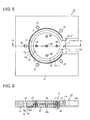
- FIG. 5 is a bottom plan view of a top mold member
- FIG. 6 is a cross sectional view taken along the plane indicated by the line 6-6 of Fig. 5;
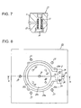
- FIG. 7 is an enlarged view of a window C of Fig. 6;
- FIG. 8 is a top plan view of a bottom mold member member
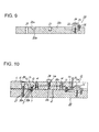
- FIG. 9 is a cross sectional view taken along the plane indicated by the line 9-9 of Fig. 8.
- FIG.10 is a cross sectional view of a mold in a molding state.
- the resolver 1 shown in Fig. 1 is used to detect deviation angles and the like and includes an annular rotor stack 3, which is installed in a rotatable manner inside an annular stator stack 2.
- the stator stack 2 is formed such that, multiple yoke plates 4, which are made by press punching thin silicone steel plates into the shape shown in Fig. 4, are laminated and fixed with crimping to create a stator core 5 with a designated thickness.
- a winding portion and signal output portion of the stator core 5 are molded by resin molding material 6, which is an insulation material (see Figs. 1 to 3.).
- fixed magnetic poles 4b (ten in the drawing) , which project radially inward from the internal surface of a yoke body 4a.
- Arcuate teeth 4c are formed integrally on the tips of each fixed magnetic pole 4b.
- a signal output portion 4d is provided integrally on a portion of the periphery of the yoke body 4a. The signal output portion projects in an outward direction as shown.
- multiple dowels 4e for crimping are formed on the yoke body 4a and fixed magnetic poles 4b of the yoke plates 4.
- Windings (excitation winding and output winding) 7 are coiled around each of the fixed magnetic poles 4b of the stator core 5, as shown in Fig. 3. Multiple lead lines 8, which are connected to the windings 7, are led out from the signal output portion 4d.
- the stator stack 2 is structured by molding a protective coating of the resin molding material 6 on the winding portion of the stator core 5 (the magnetic poles about which the windings 7 are coiled) and the signal output portion 4d.
- a winding portion and output signal portion 4d of the stack 2 are molded by injecting a fused resin molding material into a space formed between a top mold member 10 and a bottom mold member 20 from an injection molder, which is not illustrated, when the ring-shaped stack 2 of the resolver 1 and a coiled winding 7 are sandwiched between the top mold member 10 and bottom mold member 20.
- a circular recess 11a As shown in Figs. 5 and 6, a circular recess 11a, the diameter of which is approximately equal to the internal diameter of the stack 2, is formed in the center of the bottom of a body 11 of a top mold member 10.
- a movable part 12, which is disc-shaped, is fitted in the circular recess 11a and can move in an axial direction (vertical direction in Fig. 6).
- Multiple springs 13 urge the disc in a downward direction.
- the movable disc 12 is attached with multiple pins 14 (four in the illustrated example) to the body 11 so that it can be moved in the axial direction.
- the springs 13 are coiled around the pins 14, respectively, as shown. Therefore, as shown in Figs. 5 and 6, when the top mold member 10 is not connected to the bottom mold member 20, a gap is formed between the body 11 and movable disc 12 in the circular recess 11a, and the gap is set to a dimension that is greater than the variation of the thickness of the stack 2.
- a threaded hole 12a is formed in the center of the movable disc 12, and a through-hole 11b is formed in the body 11 in alignment with the threaded hole 12a.
- An inner groove 11c which covers one side of the winding portion and signal output portion 4d of the stack 2 during molding, is formed outward of the circular recess 11a of the top mold member 10.
- the inner groove 11c includes an annular portion 11c-1, which covers one side of the winding portion of the stack 2, and a radial portion 11c-2, which covers one side of the output signal portion 4d of the stack 2.
- a notch 11d is formed on the radial portion 11c-2 of the groove 11c.
- a teeming hole 11e which extends in the vertical direction of Fig. 6, opens on the surface of the body 11.
- annular outer groove 11f which contacts a side of the stack 2 (stator core 5) during molding, is located outward from the inner groove 11c.
- a small annular groove 11g is located outward from the outer groove 11f, as shown.
- a plurality (five in the illustrated example) of leveled bolt holes 15 are provided outside of the groove 11g in the top mold member 10.
- annular outer groove 20a which corresponds to the outer groove 11f of the top mold member 10 is formed in the top of a bottommoldmember 20.
- the external diameter of the outer groove 20a is approximately equal to the external diameter of the stack 2.
- an inner annular groove 20b of the bottom mold member 20, which corresponds to the inner annular groove 11c of the top mold member 10 is formed in the top of the bottom mold member 20 along the internal edge of the outer annular outer groove 20a.
- a cylindrical projection 20c the diameter of which is approximately equal to the internal diameter of the stack 2, is formed at the center of the bottom mold member 20, as shown in Fig. 9.
- the outer groove 20a of the bottom mold member 20 contacts the side of the stack 2 (stator core 5) during molding, as shown in Fig. 10, and the inner groove 20b covers one side of the winding portion and signal output portion 4d of the stack 2.
- the inner groove 20b of the bottom mold member 20 includes an annular portion 20b-1, which covers one side of the winding portion of the stack 2, and a radial portion 20b-2, which covers one side of the signal output portion 4d of the stack 2.
- a central air escape hole 21 is formed in the center of the cylindrical projection 20c of the bottom mold member 20, and a plurality (four in the illustrated example) of additional air escape holes 22 are formed around the central air escape hole 21.
- lower threaded holes 27, the number of which corresponds to the number of upper bolt holes 15 in the top mold member 10, are formed around the outer groove 20a in the bottom mold member 20 to align with the upper bolt holes 15.
- the winding portion and the signal output portion 4d of the stack 2 are resin molded using the top mold member 10 and the bottom mold member 20.
- the stack 2 (stator core 5) is fitted on the bottom mold member 20. That is, the internal edge of the stack 2 is fitted on the cylindrical projection 20c of the bottom mold member 20, and one side of the stack 2 contacts the outer groove 20a of the bottom mold member 20. The external edge of the signal output portion of the stack 2 is caught by the catch piece 23.
- the top mold member 10 is placed over the bottom mold member 20 with the movable disc 12 facing down. Then the movable disc 12 is closely fitted to the top of the cylindrical projection 20c due to the force of the springs 13. At the same time, the outer groove 11c of the top mold member 10 contacts the side of the stack 2 (stator core 5). If the thickness dimension of the stack 2 varies, the body 11, other than the movable disc 12 of the top mold member 10, can be vertically moved to accommodate unevenness in thickness of the stack 2, while the movable disc 12 of the top mold member 10 is maintained in close fitting engagement with the bottom mold member 20. Therefore, the vertical movement of the body 11 absorbs any unevenness (variation) in the thickness of the stack 2.
- the total axial dimension of the space created by the grooves 11f and 20a as measured in the vertical direction of Fig. 10 is designed to be a slightly less than the thickness of the stack 2.
- the movable disc 12 is fastened by inserting a bolt 28 in a bolt hole 11b, which is formed in the body 11 and threading the bolt 28 into a threaded hole 12a, which is formed in the movable disc 12. Then, the close fit between the movable disc and the bottom mold member 20 is maintained.
- top mold member 10 and the bottom mold member 20 are held together by bolts 29, which fit respectively in a plurality of bolt holes 15 formed in the top mold member 10.
- the bolts 29 are threaded into threaded holes 27 formed in the bottom mold member 20.
- a fused resin mold material in injected into the space formed between the top mold member 10 and the bottom mold member 20 from an injected molder (not shown).
- fused resin molding material appears at the teeming hole 11e formed on the top mold member 10, the fused resin molding material fills the space formed between the top mold member 10 and the bottom mold member 20.
- the top mold member 10 and the bottom mold member 20 are disassembled and the stack 2 is removed. Then, the winding portion and the signal output portion 4d of the stack 2 are molded with the resin molding material 6 as shown in Figs. 1 to 3.
- a co-polymerizing polyester hot melt that has no glass transition point within the range of temperatures to which the resolver is exposed is used as the resin molding material 6.
- the glass transition point temperature of the co-polymerizing polyester hot melt is -70°C
- the glass transition point temperature of the PBT (polybutylene telephtalate) is 10°C
- the movable disc 12 mounted on the top mold member 10 of the body 11 is closely engaged with the bottom mold member 20.
- the body 11 of the top mold member 10 is allowed to move vertically with respect to the movable disc 12 to accommodate the unevenness in the stack 2. Therefore, the stack 2 is always engaged between the body 11 and the bottom mold member 20. Therefore, no gap is created between the stack 2 and the top mold member 10 and between the stack and the bottom mold member 20. Thus, there is no flow of the resin molding material 6 into such a gap. Consequently, leakage of the resin molding material 6 is prevented, which stabilizes the quality of the stack 2 and the resolver 1.
- a co-polymerizing polyester hot melt which has no glass transition point within the range of temperatures to which the resolver is exposed, is used as the resin molding material 6. Therefore the resin molding material 6 is not affected by the environmental conditions to which the resolver is exposed. Thus, even when the winding of the resolver 1 has thin windings, the windings are protected by the resin molding material 6, and defects, such as a disconnection or a layer short circuit of the windings 7, are prevented.
- the protection of the winding of stack 2 by resin molding material 6 improves the durability (environmental endurance) against, for example, dust, oscillations or impact.
- the movable disc 12 is provided on the top mold, however, having the movable disc 12 on the bottom mold member provides the same result.
Landscapes
- Engineering & Computer Science (AREA)
- Power Engineering (AREA)
- Manufacturing & Machinery (AREA)
- Manufacture Of Motors, Generators (AREA)
- Transmission And Conversion Of Sensor Element Output (AREA)
- Moulds For Moulding Plastics Or The Like (AREA)
- Injection Moulding Of Plastics Or The Like (AREA)
- Insulating Of Coils (AREA)
Abstract
Description
Claims (5)
- A resin molding method for protecting a winding (7) of a resolver (1) comprising:providing a first mold member(10), a second mold member (20), and a movable part (12), wherein the movable part (12) is movable with respect to the mold members (10, 20);urging the movable part (12) toward the second mold member (20) such that the movable part (12) is closely engaged with the second mold member (20) while an annular stator (2) of the resolver (1) is sandwiched between the mold members (10, 20) in a manner such that the annular stator (2) surrounds the movable part (12);injecting a fused resin molding material into a space formed between the first mold member (10) and the second mold member (20), when the stator (2), which includes the winding (7), is sandwiched between the first mold member (10) and the second mold member (20) to cover the winding (7) with the molding material.
- The method according to claim 1, wherein a cylindrical projection (20c) of the second mold member (20) extends into an inner opening of the stator (2), and the movable part (12) is closely engaged with the cylindrical projection (20c) during the injecting.
- The method according to claim 1, wherein the molding material is a co-polymerizing polyester hot melt that has no glass transition point within a range of temperatures to which the resolver (1) is normally exposed.
- The method according to claim 2, wherein the molding material is a co-polymerizing polyester hot melt that has no glass transition point within a range of temperatures to which the resolver (1) is normally exposed.
- The method according to claim 1, wherein the movable part (12) is fitted within an inner opening of the stator (2) during the injecting.
Applications Claiming Priority (2)
| Application Number | Priority Date | Filing Date | Title |
|---|---|---|---|
| JP2003111477A JP3941945B2 (en) | 2003-04-16 | 2003-04-16 | Resin mold method for winding winding of resolver |
| JP2003111477 | 2003-04-16 |
Publications (3)
| Publication Number | Publication Date |
|---|---|
| EP1471624A2 true EP1471624A2 (en) | 2004-10-27 |
| EP1471624A3 EP1471624A3 (en) | 2004-12-22 |
| EP1471624B1 EP1471624B1 (en) | 2007-04-25 |
Family
ID=32959565
Family Applications (1)
| Application Number | Title | Priority Date | Filing Date |
|---|---|---|---|
| EP04009156A Expired - Lifetime EP1471624B1 (en) | 2003-04-16 | 2004-04-16 | Method of molding resin to protect a resolver winding |
Country Status (5)
| Country | Link |
|---|---|
| US (1) | US7347963B2 (en) |
| EP (1) | EP1471624B1 (en) |
| JP (1) | JP3941945B2 (en) |
| AT (1) | ATE360912T1 (en) |
| DE (1) | DE602004006046T2 (en) |
Cited By (4)
| Publication number | Priority date | Publication date | Assignee | Title |
|---|---|---|---|---|
| CN102141412A (en) * | 2010-01-11 | 2011-08-03 | 通用汽车环球科技运作有限责任公司 | Resolver with locating feature |
| EP2280247A4 (en) * | 2008-05-20 | 2013-12-25 | Toyota Motor Co Ltd | COORDINATE CONVERTERS |
| CN105428055A (en) * | 2015-11-30 | 2016-03-23 | 许继集团有限公司 | Transformer winding mold and mold disassembling tool |
| EP3197030A4 (en) * | 2014-08-21 | 2018-04-11 | Mitsubishi Electric Corporation | Resolver |
Families Citing this family (3)
| Publication number | Priority date | Publication date | Assignee | Title |
|---|---|---|---|---|
| US7467456B2 (en) * | 2006-03-02 | 2008-12-23 | Hiwin Mikrosystem Corp. | Method of arranging a resolver |
| JP4845236B2 (en) * | 2007-02-28 | 2011-12-28 | 愛三工業株式会社 | Resolver for automobile drive motor |
| CN113491057B (en) * | 2019-01-14 | 2023-12-22 | 深圳配天机器人技术有限公司 | An extrusion shaping component, a lamination shaping system and a lamination shaping method |
Family Cites Families (26)
| Publication number | Priority date | Publication date | Assignee | Title |
|---|---|---|---|---|
| US3813763A (en) * | 1970-12-17 | 1974-06-04 | Gen Electric | Laminated structure with insulating member formed in situ thereon and method for making same |
| US3963949A (en) * | 1972-10-26 | 1976-06-15 | General Electric Company | Laminated structure with insulating member formed in situ thereon |
| JPS55160948A (en) | 1979-06-01 | 1980-12-15 | Toshiba Corp | Molded motor |
| JPS5720154A (en) | 1980-07-11 | 1982-02-02 | Hitachi Ltd | Molding device of rotary electric machine stator |
| US4470786A (en) * | 1981-07-28 | 1984-09-11 | Omron Tateisi Electronics Co. | Molding apparatus with retractable preform support pins |
| US4452420A (en) * | 1982-09-30 | 1984-06-05 | Lynn Lundquist | Compensating core pin for plastic injection molds |
| JPS60152256A (en) * | 1984-01-18 | 1985-08-10 | Atsugi Motor Parts Co Ltd | Manufacture of motor |
| JPS60249849A (en) | 1984-05-22 | 1985-12-10 | Matsushita Electric Ind Co Ltd | Mold for insulating core |
| US4805991A (en) * | 1986-03-13 | 1989-02-21 | Canon Kabushiki Kaisha | Multi-layer resin molded article and method of making the same |
| KR930005345B1 (en) * | 1986-10-23 | 1993-06-17 | 후지덴기 가부시기가이샤 | Stator housing and rotor of mini-motor |
| JPH01174427A (en) * | 1987-12-28 | 1989-07-11 | Koyo Seiko Co Ltd | Method for molding spindle housing |
| JPH01186143A (en) * | 1988-01-19 | 1989-07-25 | Olympus Optical Co Ltd | Coreless armature and manufacture thereof, and molding tool for coreless armature |
| DE4110585C2 (en) | 1991-04-02 | 1994-06-30 | Hohenloher Spulenkoerper | Device for producing a core of an electrical coil provided with an insulation layer and core which can be produced with the device |
| US5268607A (en) * | 1992-09-09 | 1993-12-07 | Webster Plastics | Molded resin motor housing |
| DE4331086A1 (en) | 1993-09-11 | 1995-03-16 | Herberts Gmbh | Process for the fixation of wound goods with radically polymerizable masses |
| JP3111015B2 (en) * | 1996-02-29 | 2000-11-20 | 株式会社日本製鋼所 | Mold for injection and compression molding |
| US5853643A (en) * | 1996-07-19 | 1998-12-29 | Bauer; Scott V. | Method for constructing a liquid-impervious electric motor assembly |
| DE19746605A1 (en) * | 1996-10-28 | 1998-06-10 | Papst Motoren Gmbh & Co Kg | DC motor stator insulation method |
| US6558596B1 (en) * | 1999-03-29 | 2003-05-06 | Gemtron Corporation | Method of molding a peripherally encapsulated product under heat and pressure utilizing sheet molding compound (SMC) or bulk molding compound (BMC) |
| JP3450223B2 (en) * | 1999-05-27 | 2003-09-22 | Necエレクトロニクス株式会社 | Semiconductor device sealing mold and semiconductor device sealing method |
| DE10023208A1 (en) * | 2000-05-12 | 2001-11-15 | Alstom Power Nv | Insulation of stator windings by injection molding |
| JP3411007B2 (en) | 2000-05-16 | 2003-05-26 | 多摩川精機株式会社 | Method and structure for winding protection of resolver |
| JP2001327105A (en) * | 2000-05-17 | 2001-11-22 | Fujitsu General Ltd | Motor rotor and method of manufacturing the same |
| JP4674679B2 (en) | 2000-11-29 | 2011-04-20 | ミネベア株式会社 | Stator structure of variable reluctance resolver |
| JP2003344107A (en) * | 2002-05-31 | 2003-12-03 | Tamagawa Seiki Co Ltd | Stator structure for rotation detector |
| US7036206B2 (en) * | 2002-08-09 | 2006-05-02 | Delphi Technologies, Inc. | Process for preparing an over molded motor stator structure |
-
2003
- 2003-04-16 JP JP2003111477A patent/JP3941945B2/en not_active Expired - Fee Related
-
2004
- 2004-04-16 DE DE602004006046T patent/DE602004006046T2/en not_active Expired - Lifetime
- 2004-04-16 EP EP04009156A patent/EP1471624B1/en not_active Expired - Lifetime
- 2004-04-16 AT AT04009156T patent/ATE360912T1/en not_active IP Right Cessation
- 2004-04-16 US US10/826,135 patent/US7347963B2/en not_active Expired - Fee Related
Cited By (6)
| Publication number | Priority date | Publication date | Assignee | Title |
|---|---|---|---|---|
| EP2280247A4 (en) * | 2008-05-20 | 2013-12-25 | Toyota Motor Co Ltd | COORDINATE CONVERTERS |
| CN102141412A (en) * | 2010-01-11 | 2011-08-03 | 通用汽车环球科技运作有限责任公司 | Resolver with locating feature |
| CN102141412B (en) * | 2010-01-11 | 2014-02-19 | 通用汽车环球科技运作有限责任公司 | Resolver with locating feature |
| EP3197030A4 (en) * | 2014-08-21 | 2018-04-11 | Mitsubishi Electric Corporation | Resolver |
| US10627258B2 (en) | 2014-08-21 | 2020-04-21 | Mitsubishi Electric Corporation | Resolver |
| CN105428055A (en) * | 2015-11-30 | 2016-03-23 | 许继集团有限公司 | Transformer winding mold and mold disassembling tool |
Also Published As
| Publication number | Publication date |
|---|---|
| JP2004320894A (en) | 2004-11-11 |
| ATE360912T1 (en) | 2007-05-15 |
| EP1471624A3 (en) | 2004-12-22 |
| JP3941945B2 (en) | 2007-07-11 |
| DE602004006046T2 (en) | 2007-12-27 |
| EP1471624B1 (en) | 2007-04-25 |
| US7347963B2 (en) | 2008-03-25 |
| US20050077650A1 (en) | 2005-04-14 |
| DE602004006046D1 (en) | 2007-06-06 |
Similar Documents
| Publication | Publication Date | Title |
|---|---|---|
| EP1253606B1 (en) | Stick-type ignition coil having improved structure against crack or dielectric discharge | |
| US7347963B2 (en) | Method of molding resin to protect a resolver winding | |
| EP0315419B1 (en) | Encapsulated stepper motor | |
| US7183886B2 (en) | Inductance device | |
| US20030030349A1 (en) | Stator structure of variable reluctance resolver | |
| JP4209407B2 (en) | Ignition device for internal combustion engine | |
| JP2013229406A (en) | Reactor | |
| US7880360B2 (en) | Stator assembly | |
| US6426032B1 (en) | Method of injection-molding coil spool of ignition coil device | |
| US6369380B1 (en) | Light receiver unit having a light receiving element and a packaging cover | |
| US20210265107A1 (en) | Ignition coil | |
| CN101931306B (en) | Rotor supporting structure for slim step motor | |
| JPH1151949A (en) | Rotation sensor | |
| JP2019062652A (en) | Stator unit, motor, and method of manufacturing stator unit | |
| JPH0128666Y2 (en) | ||
| JP7507004B2 (en) | Current Sensors | |
| JP2025084162A (en) | Molded coil and reactor, and manufacturing method of molded coil and reactor | |
| US7145426B2 (en) | Ignition coil for internal combustion engine | |
| US7808360B1 (en) | Cushioning materials and method for applying the same to resin cast transformers | |
| JP6491887B2 (en) | Ignition coil for internal combustion engine | |
| JP5071279B2 (en) | Ignition coil | |
| JPH0543457Y2 (en) | ||
| JP3572042B2 (en) | Magnetic sensor | |
| JP6491886B2 (en) | Ignition coil for internal combustion engine | |
| JPS6210975Y2 (en) |
Legal Events
| Date | Code | Title | Description |
|---|---|---|---|
| PUAI | Public reference made under article 153(3) epc to a published international application that has entered the european phase |
Free format text: ORIGINAL CODE: 0009012 |
|
| AK | Designated contracting states |
Kind code of ref document: A2 Designated state(s): AT BE BG CH CY CZ DE DK EE ES FI FR GB GR HU IE IT LI LU MC NL PL PT RO SE SI SK TR |
|
| AX | Request for extension of the european patent |
Extension state: AL HR LT LV MK |
|
| PUAL | Search report despatched |
Free format text: ORIGINAL CODE: 0009013 |
|
| AK | Designated contracting states |
Kind code of ref document: A3 Designated state(s): AT BE BG CH CY CZ DE DK EE ES FI FR GB GR HU IE IT LI LU MC NL PL PT RO SE SI SK TR |
|
| AX | Request for extension of the european patent |
Extension state: AL HR LT LV MK |
|
| RIC1 | Information provided on ipc code assigned before grant |
Ipc: 7H 02K 15/12 B Ipc: 7H 02K 15/10 A |
|
| 17P | Request for examination filed |
Effective date: 20050617 |
|
| AKX | Designation fees paid |
Designated state(s): AT BE BG CH CY CZ DE DK EE ES FI FR GB GR HU IE IT LI LU MC NL PL PT RO SE SI SK TR |
|
| GRAP | Despatch of communication of intention to grant a patent |
Free format text: ORIGINAL CODE: EPIDOSNIGR1 |
|
| GRAS | Grant fee paid |
Free format text: ORIGINAL CODE: EPIDOSNIGR3 |
|
| GRAA | (expected) grant |
Free format text: ORIGINAL CODE: 0009210 |
|
| AK | Designated contracting states |
Kind code of ref document: B1 Designated state(s): AT BE BG CH CY CZ DE DK EE ES FI FR GB GR HU IE IT LI LU MC NL PL PT RO SE SI SK TR |
|
| PG25 | Lapsed in a contracting state [announced via postgrant information from national office to epo] |
Ref country code: FI Free format text: LAPSE BECAUSE OF FAILURE TO SUBMIT A TRANSLATION OF THE DESCRIPTION OR TO PAY THE FEE WITHIN THE PRESCRIBED TIME-LIMIT Effective date: 20070425 Ref country code: LI Free format text: LAPSE BECAUSE OF FAILURE TO SUBMIT A TRANSLATION OF THE DESCRIPTION OR TO PAY THE FEE WITHIN THE PRESCRIBED TIME-LIMIT Effective date: 20070425 Ref country code: CH Free format text: LAPSE BECAUSE OF FAILURE TO SUBMIT A TRANSLATION OF THE DESCRIPTION OR TO PAY THE FEE WITHIN THE PRESCRIBED TIME-LIMIT Effective date: 20070425 |
|
| REG | Reference to a national code |
Ref country code: GB Ref legal event code: FG4D |
|
| REG | Reference to a national code |
Ref country code: IE Ref legal event code: FG4D |
|
| REG | Reference to a national code |
Ref country code: CH Ref legal event code: EP |
|
| REF | Corresponds to: |
Ref document number: 602004006046 Country of ref document: DE Date of ref document: 20070606 Kind code of ref document: P |
|
| PG25 | Lapsed in a contracting state [announced via postgrant information from national office to epo] |
Ref country code: SE Free format text: LAPSE BECAUSE OF FAILURE TO SUBMIT A TRANSLATION OF THE DESCRIPTION OR TO PAY THE FEE WITHIN THE PRESCRIBED TIME-LIMIT Effective date: 20070725 |
|
| PG25 | Lapsed in a contracting state [announced via postgrant information from national office to epo] |
Ref country code: ES Free format text: LAPSE BECAUSE OF FAILURE TO SUBMIT A TRANSLATION OF THE DESCRIPTION OR TO PAY THE FEE WITHIN THE PRESCRIBED TIME-LIMIT Effective date: 20070805 |
|
| PG25 | Lapsed in a contracting state [announced via postgrant information from national office to epo] |
Ref country code: PT Free format text: LAPSE BECAUSE OF FAILURE TO SUBMIT A TRANSLATION OF THE DESCRIPTION OR TO PAY THE FEE WITHIN THE PRESCRIBED TIME-LIMIT Effective date: 20070925 |
|
| REG | Reference to a national code |
Ref country code: CH Ref legal event code: PL |
|
| NLV1 | Nl: lapsed or annulled due to failure to fulfill the requirements of art. 29p and 29m of the patents act | ||
| PG25 | Lapsed in a contracting state [announced via postgrant information from national office to epo] |
Ref country code: AT Free format text: LAPSE BECAUSE OF FAILURE TO SUBMIT A TRANSLATION OF THE DESCRIPTION OR TO PAY THE FEE WITHIN THE PRESCRIBED TIME-LIMIT Effective date: 20070425 Ref country code: PL Free format text: LAPSE BECAUSE OF FAILURE TO SUBMIT A TRANSLATION OF THE DESCRIPTION OR TO PAY THE FEE WITHIN THE PRESCRIBED TIME-LIMIT Effective date: 20070425 |
|
| PG25 | Lapsed in a contracting state [announced via postgrant information from national office to epo] |
Ref country code: BE Free format text: LAPSE BECAUSE OF FAILURE TO SUBMIT A TRANSLATION OF THE DESCRIPTION OR TO PAY THE FEE WITHIN THE PRESCRIBED TIME-LIMIT Effective date: 20070425 |
|
| PG25 | Lapsed in a contracting state [announced via postgrant information from national office to epo] |
Ref country code: NL Free format text: LAPSE BECAUSE OF FAILURE TO SUBMIT A TRANSLATION OF THE DESCRIPTION OR TO PAY THE FEE WITHIN THE PRESCRIBED TIME-LIMIT Effective date: 20070425 Ref country code: CZ Free format text: LAPSE BECAUSE OF FAILURE TO SUBMIT A TRANSLATION OF THE DESCRIPTION OR TO PAY THE FEE WITHIN THE PRESCRIBED TIME-LIMIT Effective date: 20070425 Ref country code: DK Free format text: LAPSE BECAUSE OF FAILURE TO SUBMIT A TRANSLATION OF THE DESCRIPTION OR TO PAY THE FEE WITHIN THE PRESCRIBED TIME-LIMIT Effective date: 20070425 Ref country code: SI Free format text: LAPSE BECAUSE OF FAILURE TO SUBMIT A TRANSLATION OF THE DESCRIPTION OR TO PAY THE FEE WITHIN THE PRESCRIBED TIME-LIMIT Effective date: 20070425 Ref country code: BG Free format text: LAPSE BECAUSE OF FAILURE TO SUBMIT A TRANSLATION OF THE DESCRIPTION OR TO PAY THE FEE WITHIN THE PRESCRIBED TIME-LIMIT Effective date: 20070725 |
|
| PG25 | Lapsed in a contracting state [announced via postgrant information from national office to epo] |
Ref country code: SK Free format text: LAPSE BECAUSE OF FAILURE TO SUBMIT A TRANSLATION OF THE DESCRIPTION OR TO PAY THE FEE WITHIN THE PRESCRIBED TIME-LIMIT Effective date: 20070425 |
|
| PLBE | No opposition filed within time limit |
Free format text: ORIGINAL CODE: 0009261 |
|
| STAA | Information on the status of an ep patent application or granted ep patent |
Free format text: STATUS: NO OPPOSITION FILED WITHIN TIME LIMIT |
|
| 26N | No opposition filed |
Effective date: 20080128 |
|
| PG25 | Lapsed in a contracting state [announced via postgrant information from national office to epo] |
Ref country code: GR Free format text: LAPSE BECAUSE OF FAILURE TO SUBMIT A TRANSLATION OF THE DESCRIPTION OR TO PAY THE FEE WITHIN THE PRESCRIBED TIME-LIMIT Effective date: 20070726 |
|
| PG25 | Lapsed in a contracting state [announced via postgrant information from national office to epo] |
Ref country code: RO Free format text: LAPSE BECAUSE OF FAILURE TO SUBMIT A TRANSLATION OF THE DESCRIPTION OR TO PAY THE FEE WITHIN THE PRESCRIBED TIME-LIMIT Effective date: 20070425 |
|
| PG25 | Lapsed in a contracting state [announced via postgrant information from national office to epo] |
Ref country code: MC Free format text: LAPSE BECAUSE OF NON-PAYMENT OF DUE FEES Effective date: 20080430 |
|
| PG25 | Lapsed in a contracting state [announced via postgrant information from national office to epo] |
Ref country code: EE Free format text: LAPSE BECAUSE OF FAILURE TO SUBMIT A TRANSLATION OF THE DESCRIPTION OR TO PAY THE FEE WITHIN THE PRESCRIBED TIME-LIMIT Effective date: 20070425 |
|
| PG25 | Lapsed in a contracting state [announced via postgrant information from national office to epo] |
Ref country code: IE Free format text: LAPSE BECAUSE OF NON-PAYMENT OF DUE FEES Effective date: 20080416 |
|
| PG25 | Lapsed in a contracting state [announced via postgrant information from national office to epo] |
Ref country code: CY Free format text: LAPSE BECAUSE OF FAILURE TO SUBMIT A TRANSLATION OF THE DESCRIPTION OR TO PAY THE FEE WITHIN THE PRESCRIBED TIME-LIMIT Effective date: 20070425 |
|
| PGFP | Annual fee paid to national office [announced via postgrant information from national office to epo] |
Ref country code: GB Payment date: 20100325 Year of fee payment: 7 |
|
| PG25 | Lapsed in a contracting state [announced via postgrant information from national office to epo] |
Ref country code: HU Free format text: LAPSE BECAUSE OF FAILURE TO SUBMIT A TRANSLATION OF THE DESCRIPTION OR TO PAY THE FEE WITHIN THE PRESCRIBED TIME-LIMIT Effective date: 20071026 Ref country code: LU Free format text: LAPSE BECAUSE OF NON-PAYMENT OF DUE FEES Effective date: 20080416 |
|
| PGFP | Annual fee paid to national office [announced via postgrant information from national office to epo] |
Ref country code: FR Payment date: 20100521 Year of fee payment: 7 |
|
| PG25 | Lapsed in a contracting state [announced via postgrant information from national office to epo] |
Ref country code: TR Free format text: LAPSE BECAUSE OF FAILURE TO SUBMIT A TRANSLATION OF THE DESCRIPTION OR TO PAY THE FEE WITHIN THE PRESCRIBED TIME-LIMIT Effective date: 20070425 |
|
| PGFP | Annual fee paid to national office [announced via postgrant information from national office to epo] |
Ref country code: DE Payment date: 20100430 Year of fee payment: 7 Ref country code: IT Payment date: 20100423 Year of fee payment: 7 |
|
| GBPC | Gb: european patent ceased through non-payment of renewal fee |
Effective date: 20110416 |
|
| REG | Reference to a national code |
Ref country code: FR Ref legal event code: ST Effective date: 20111230 |
|
| PG25 | Lapsed in a contracting state [announced via postgrant information from national office to epo] |
Ref country code: DE Free format text: LAPSE BECAUSE OF NON-PAYMENT OF DUE FEES Effective date: 20111101 Ref country code: FR Free format text: LAPSE BECAUSE OF NON-PAYMENT OF DUE FEES Effective date: 20110502 |
|
| PG25 | Lapsed in a contracting state [announced via postgrant information from national office to epo] |
Ref country code: IT Free format text: LAPSE BECAUSE OF NON-PAYMENT OF DUE FEES Effective date: 20110416 Ref country code: GB Free format text: LAPSE BECAUSE OF NON-PAYMENT OF DUE FEES Effective date: 20110416 |
|
| REG | Reference to a national code |
Ref country code: DE Ref legal event code: R119 Ref document number: 602004006046 Country of ref document: DE Effective date: 20111101 |