EP1471546A2 - Method of injecting an electrolytic solution to fill a photoelectrochemical cell - Google Patents
Method of injecting an electrolytic solution to fill a photoelectrochemical cell Download PDFInfo
- Publication number
- EP1471546A2 EP1471546A2 EP04009443A EP04009443A EP1471546A2 EP 1471546 A2 EP1471546 A2 EP 1471546A2 EP 04009443 A EP04009443 A EP 04009443A EP 04009443 A EP04009443 A EP 04009443A EP 1471546 A2 EP1471546 A2 EP 1471546A2
- Authority
- EP
- European Patent Office
- Prior art keywords
- electrolytic solution
- injecting
- solution containing
- containing vessel
- dye
- Prior art date
- Legal status (The legal status is an assumption and is not a legal conclusion. Google has not performed a legal analysis and makes no representation as to the accuracy of the status listed.)
- Withdrawn
Links
Images



Classifications
-
- H—ELECTRICITY
- H01—ELECTRIC ELEMENTS
- H01G—CAPACITORS; CAPACITORS, RECTIFIERS, DETECTORS, SWITCHING DEVICES, LIGHT-SENSITIVE OR TEMPERATURE-SENSITIVE DEVICES OF THE ELECTROLYTIC TYPE
- H01G9/00—Electrolytic capacitors, rectifiers, detectors, switching devices, light-sensitive or temperature-sensitive devices; Processes of their manufacture
- H01G9/20—Light-sensitive devices
- H01G9/2068—Panels or arrays of photoelectrochemical cells, e.g. photovoltaic modules based on photoelectrochemical cells
-
- E—FIXED CONSTRUCTIONS
- E03—WATER SUPPLY; SEWERAGE
- E03C—DOMESTIC PLUMBING INSTALLATIONS FOR FRESH WATER OR WASTE WATER; SINKS
- E03C1/00—Domestic plumbing installations for fresh water or waste water; Sinks
- E03C1/12—Plumbing installations for waste water; Basins or fountains connected thereto; Sinks
- E03C1/122—Pipe-line systems for waste water in building
- E03C1/1222—Arrangements of devices in domestic waste water pipe-line systems
-
- H—ELECTRICITY
- H01—ELECTRIC ELEMENTS
- H01G—CAPACITORS; CAPACITORS, RECTIFIERS, DETECTORS, SWITCHING DEVICES, LIGHT-SENSITIVE OR TEMPERATURE-SENSITIVE DEVICES OF THE ELECTROLYTIC TYPE
- H01G9/00—Electrolytic capacitors, rectifiers, detectors, switching devices, light-sensitive or temperature-sensitive devices; Processes of their manufacture
- H01G9/20—Light-sensitive devices
- H01G9/2004—Light-sensitive devices characterised by the electrolyte, e.g. comprising an organic electrolyte
-
- H—ELECTRICITY
- H01—ELECTRIC ELEMENTS
- H01G—CAPACITORS; CAPACITORS, RECTIFIERS, DETECTORS, SWITCHING DEVICES, LIGHT-SENSITIVE OR TEMPERATURE-SENSITIVE DEVICES OF THE ELECTROLYTIC TYPE
- H01G9/00—Electrolytic capacitors, rectifiers, detectors, switching devices, light-sensitive or temperature-sensitive devices; Processes of their manufacture
- H01G9/20—Light-sensitive devices
- H01G9/2027—Light-sensitive devices comprising an oxide semiconductor electrode
- H01G9/2031—Light-sensitive devices comprising an oxide semiconductor electrode comprising titanium oxide, e.g. TiO2
-
- E—FIXED CONSTRUCTIONS
- E03—WATER SUPPLY; SEWERAGE
- E03C—DOMESTIC PLUMBING INSTALLATIONS FOR FRESH WATER OR WASTE WATER; SINKS
- E03C1/00—Domestic plumbing installations for fresh water or waste water; Sinks
- E03C1/12—Plumbing installations for waste water; Basins or fountains connected thereto; Sinks
- E03C2001/1206—Pipes with specific features for influencing flow characteristics
-
- E—FIXED CONSTRUCTIONS
- E03—WATER SUPPLY; SEWERAGE
- E03C—DOMESTIC PLUMBING INSTALLATIONS FOR FRESH WATER OR WASTE WATER; SINKS
- E03C2201/00—Details, devices or methods not otherwise provided for
- E03C2201/60—Reducing noise in plumbing systems
-
- Y—GENERAL TAGGING OF NEW TECHNOLOGICAL DEVELOPMENTS; GENERAL TAGGING OF CROSS-SECTIONAL TECHNOLOGIES SPANNING OVER SEVERAL SECTIONS OF THE IPC; TECHNICAL SUBJECTS COVERED BY FORMER USPC CROSS-REFERENCE ART COLLECTIONS [XRACs] AND DIGESTS
- Y02—TECHNOLOGIES OR APPLICATIONS FOR MITIGATION OR ADAPTATION AGAINST CLIMATE CHANGE
- Y02E—REDUCTION OF GREENHOUSE GAS [GHG] EMISSIONS, RELATED TO ENERGY GENERATION, TRANSMISSION OR DISTRIBUTION
- Y02E10/00—Energy generation through renewable energy sources
- Y02E10/50—Photovoltaic [PV] energy
- Y02E10/542—Dye sensitized solar cells
-
- Y—GENERAL TAGGING OF NEW TECHNOLOGICAL DEVELOPMENTS; GENERAL TAGGING OF CROSS-SECTIONAL TECHNOLOGIES SPANNING OVER SEVERAL SECTIONS OF THE IPC; TECHNICAL SUBJECTS COVERED BY FORMER USPC CROSS-REFERENCE ART COLLECTIONS [XRACs] AND DIGESTS
- Y02—TECHNOLOGIES OR APPLICATIONS FOR MITIGATION OR ADAPTATION AGAINST CLIMATE CHANGE
- Y02P—CLIMATE CHANGE MITIGATION TECHNOLOGIES IN THE PRODUCTION OR PROCESSING OF GOODS
- Y02P70/00—Climate change mitigation technologies in the production process for final industrial or consumer products
- Y02P70/50—Manufacturing or production processes characterised by the final manufactured product
Definitions
- the present invention relates to a method of injecting an electrolytic solution, a method of manufacturing a wet-type photoelectric conversion device, and a method of manufacturing a wet-type apparatus, which are favorable when applied, for example, to the manufacture of a wet-type solar cell using a semiconductor layer comprised of semiconductor particulates, particularly a semiconductor layer comprised of semiconductor particulates sensitized by a dye.
- Solar cells are photoelectric conversion devices for converting sunlight into electrical energy, and use the sunlight as an energy source. Therefore, the solar cells have very little influence on the global environments, and are expected to spread more widely.
- the solar cells using silicon are generally classified into crystalline silicon-based solar cells using single-crystalline or polycrystalline silicon, and amorphous silicon-based solar cells.
- single-crystalline or polycrystalline silicon i.e., crystalline silicon has been used for solar cells in many cases.
- the crystalline silicon-based solar cells are higher than the amorphous silicon-based solar cells in photoelectric conversion efficiency, which indicates the performance of converting light (solar) energy into electrical energy.
- the crystalline silicon-based solar cells require much energy and time for crystal growth, and, therefore, they are low in productivity and disadvantageous on a cost basis.
- the amorphous silicon-based solar cells are characterized in that they have higher light absorption performance, permit a wider range of selection of substrate, and can be enlarged in area more easily, as compared with the crystalline silicon-based solar cells.
- the amorphous silicon-based solar cells are inferior to the crystalline silicon-based solar cells in photoelectric conversion efficiency.
- the amorphous silicon-based solar cells are higher than the crystalline silicon-based solar cells in productivity, they need a vacuum process in the manufacture thereof, like the crystalline silicon-based solar cells, so that they still exert a heavy burden on an equipment basis.
- the dye-sensitized solar cells proposed by Gratzel et al in 1991 are inexpensive, show high photoelectric conversion efficiencies, and, unlike the conventional silicon-based solar cells, do not need large-scale equipment for the production thereof. Because of such advantages, the dye-sensitized solar cells have been attracting attention (see, for example, Nature, 353, p.737 (1991)).
- the dye-sensitized solar cells have a general structure in which a semiconductor porous electrode comprising a semiconductor porous film of titanium oxide or the like formed on a transparent conductive substrate, combined with a sensitizing dye, and a counter electrode obtained by forming a platinum layer or the like on a substrate are combined with each other, and an organic electrolytic solution containing oxidation-reduction species such as iodine and iodide ions is charged into the space between the electrodes.
- the conventional method of injecting the electrolytic solution has the following problems. Since two holes are opened in the dye-sensitized solar cell, it is necessary to perform a sealing operation at two locations, for closing the holes after the injection. Besides, since the equipment for applying the negative pressure (suction) to the other hole is for exclusive use, this method requires additional equipment cost and installation time.
- the present invention has been made in order to solve the above-mentioned problems. Accordingly, it is an object of the present invention to provide a method of injecting an electrolytic solution, a method of manufacturing a wet-type photoelectric conversion device, and a method of manufacturing a variety of wet-type apparatuses using an electrolytic solution, which make it possible to inject an electrolytic solution inexpensively and speedily.
- a method of injecting an electrolytic solution for injecting the electrolytic solution into an electrolytic solution containing vessel of which a portion is opened.
- the injection of the electrolytic solution into the electrolytic solution containing vessel is conducted by utilizing a centrifugal force.
- the electrolytic solution is dropped to the opened portion of the electrolytic solution containing vessel, and the centrifugal force is applied in such a manner that at least a force in the direction from the opened portion toward the inside of the electrolytic solution containing vessel is exerted on the electrolytic solution.
- the method for applying the centrifugal force is not particularly limited.
- a method may be used in which, for example, the electrolytic solution is dropped to the opened portion of each electrolytic solution containing vessel, a single or a plurality of such electrolytic solution containing vessels are fixed on a turntable rotatable about a predetermined center so that the opened portion of each electrolytic solution containing vessel is directed inwards (toward the center), and the turntable is rotated about the center, whereby the electrolytic solution is injected into the electrolytic solution containing vessel or vessels.
- Another method may also be used in which the electrolytic solution containing vessel or vessels are fixed on the turntable before the dropping of the electrolytic solution, thereafter the electrolytic solution is dropped to the opened portion of each electrolytic solution containing vessel, and the turntable is rotated, whereby the electrolytic solution is injected into the electrolytic solution containing vessel or vessels.
- the internal size in one direction of a section of the electrolytic solution containing vessel is generally in the range of 1 to 200 ⁇ m, typically 10 to 200 ⁇ m, and more typically 20 to 150 ⁇ m.
- the internal shape of the electrolytic solution containing vessel is a rectangular parallelopiped such that the length of a side in one direction (for example, a length of 1 to 200 ⁇ m, as above-mentioned) is extremely smaller than the lengths of the other sides, and a sectional shape of the electrolytic solution containing vessel is a flat rectangle.
- the viscosity of the electrolytic solution differs depending on the kind of the electrolytic solution used, and is generally not more than 20 cp, typically not more than 10 cp.
- An electrolyte in the electrolytic solution is comprised of an oxidation-reduction pair and a solvent.
- the oxidation-reduction pair include combinations of iodine (I 2 ) with an iodine compound (a metal iodide, an organic iodide, or the like); combinations of bromine (Br 2 ) with a bromine compound (a metal bromide, an organic bromide, or the like); metal complexes such as ferrocianate/ferricyanate, ferrocene/ferricinium ion, etc.; sulfur compounds such as sodium polysulfides, alkyl thiol/alkyl disulfide, etc.; viologen dyes; and hydroquinone/quinone.
- Preferred examples of the cations in the above-mentioned metal compounds include Li, Na, K, Mg, Ca, and Cs
- preferred examples of the cations in the above-mentioned organic compounds include quaternary ammonium compounds such as tetraalkylammonium compounds, pyridinium compounds, imidazolium compounds, etc.; these examples are non-limitative examples, and a mixture of two or more of these may also be used, as required.
- the concentration of the electrolyte salt, based on the solvent, is preferably in the range of 0.05 to 5 M, more preferably 0.2 to 1 M.
- the concentration of I 2 or Br 2 is preferably in the range of 0.00005 to 1 M, more preferably 0.0001 to 0.1 M.
- Various additives such as 4-tert-butylpyridine, 2-n-propylpyridine, carboxylic acids, etc. may also be added, for the purpose of improving open circuit voltage or short-circuit current.
- the solvent in the electrolytic solution examples include water, alcohols, ethers, esters, carbonic acid esters, lactones, carboxylic acid esters, phosphoric acid trimesters, heterocyclic compounds, nitriles, ketones, amides, nitromethane, halogenated hydrocarbons, dimethyl sulfoxide, sulfolan, N-methylpyrrolidone, 1,3-dimethylimidazolidinone, 3-methyloxazolidinone, and hydrocarbons; these are non-limitative examples, and these can be used either singly or in combination of two or more thereof.
- room-temperature ionic liquids comprising a tetraalkyl-based, pyridinium-based or imidazolim-based quaternary ammonium salt can also be used as the solvent of the electrolytic solution.
- Some examples of the viscosity of the electrolytic solution generally used in a dye-sensitized wet-type solar cell are as follows: in the cases where methanol, acetonitrile, and propylene carbonate are respectively used as the solvent, the viscosity values are about 0.55 cp, about 0.38 cp, and about 2.3 cp, respectively.
- the electrolytic solution is admixed with a normal-temperature fused salt (for example, DMPII (1-propyl-2,3-dimethylimidazolium iodide) or the like) in order to lower the viscosity and thereby to smoothen the diffusion of ions, for the purpose of enhancing the photoelectric conversion efficiency of the dye-sensitized wet-type solar cell. Accordingly, the viscosity of the electrolytic solution is lower than the above-mentioned exemplary values, in many cases.
- a normal-temperature fused salt for example, DMPII (1-propyl-2,3-dimethylimidazolium iodide) or the like
- a method of manufacturing a wet-type photoelectric conversion device including the step of injecting centrifugally an electrolytic solution into a vessel having at least one opening.
- a semiconductor layer comprised of semiconductor particulates is formed on a transparent conductive substrate, a counter electrode comprised of platinum or the like is formed on another substrate, these substrates are so held that the semiconductor layer and the counter electrode are opposed to each other with a predetermined spacing therebetween, and the peripheral portions of the substrates exclusive of an opening portion for injection of the electrolytic solution are sealed with a sealing material.
- the space thus formed between the substrates becomes the electrolytic solution containing portion.
- the semiconductor particulates for example, particulates of titanium oxide having the anatase-type crystal structure may be used.
- the sealing material is not particularly limited, but it is preferable to use a material which has light resistance, an insulating property, and a moisture-proof property. Examples of the sealing material include epoxy resin, UV-curable resins, acrylic adhesives, EVA (ethylene vinyl acetate), ionomer resins, ceramics, and fusion-bonding films.
- the above descriptions relating to the first aspect of the present invention are again established, where the electrolytic solution containing portion is regarded as corresponding to the electrolytic solution containing vessel.
- a method of injecting an electrolytic solution for injecting the electrolytic solution into a space between a semiconductor electrode comprising a semiconductor with a dye and a counter electrode opposed to the semiconductor electrode.
- the method includes the steps of injecting the electrolytic solution into at least a part of the space between the semiconductor electrode and the counter electrode, and applying a centrifugal force to the semiconductor electrode and the counter electrode.
- a method of injecting an electrolytic solution for injecting the electrolytic solution into a space between a semiconductor electrode comprising a semiconductor with a dye supported thereon and a counter electrode opposed to the semiconductor electrode.
- the method includes the steps of injecting the electrolytic solution into at least a part of the space between the semiconductor electrode and the counter electrode, and rotating the semiconductor electrode and the counter electrode.
- a method of manufacturing a wet-type apparatus including the step of injecting centrifugally an electrolytic solution into a vessel having at least one opening.
- the wet-type apparatus includes the above-mentioned wet-type photoelectric conversion device, and also includes a variety of wet-type apparatuses which are each used with an electrolytic solution injected into an electrolytic solution containing portion.
- an electrolytic solution is injected into an electrolytic solution containing vessel or an electrolytic solution containing portion by utilizing a centrifugal force, whereby the injection of the electrolytic solution can be conducted inexpensively and speedily.
- Fig. 1 is a perspective view showing the condition of the dye-sensitized wet-type solar cell in the course of manufacture thereof
- Fig. 2 is a sectional view taken along line II-II of Fig. 1.
- a transparent conductive substrate 1 provided thereon with a semiconductor layer (not shown) comprised of semiconductor particles with a dye and a transparent substrate 2 provided thereon with a platinum layer (not shown) as a counter electrode are so held that the semiconductor layer and the platinum layer are opposed to each other with a predetermined spacing therebetween, and the peripheral portions of the two substrates exclusive of one side are sealed with a sealing material 3.
- a pocket-like electrolytic solution containing portion 4 in the shape of a flat rectangular parallelopiped with one end portion 4a opened is formed between the transparent conductive substrate 1 provided thereon with the semiconductor layer comprised of the semiconductor particulates and the transparent substrate 2 provided thereon with the platinum layer.
- the whole assembly of the transparent conductive substrate 1 and the transparent substrate 2 after sealed will be referred to as the dye-sensitized wet-type solar cell.
- the width W 1 is, for example, 20 to 150 ⁇ m
- the width W 2 is, for example, about 1 cm
- the length L is, for example, about 1 cm.
- the transparent conductive substrate 1 and the transparent substrate 2 are each obtained, for example, by forming a layer of indium-tin compound oxide (ITO) as a transparent electrode on a film of polyethylene terephthalate (PET).
- ITO indium-tin compound oxide
- PET polyethylene terephthalate
- the semiconductor particulates constituting the semiconductor layer for example, particulates of titanium oxide having the anatase-type crystal structure are used.
- the sealing material 3 for example, a combination of an EVA film and an epoxy adhesive is used.
- an electrolytic solution 5 is dropped to the opened one end portion 4a of the electrolytic solution containing portion 4 of the dye-sensitized wet-type solar cell.
- the amount of the electrolytic solution 5 thus dropped is the amount to be injected into the electrolytic solution containing portion 4.
- the electrolytic solution 5 for example, a solution of LiI (0.5 M), I 2 (0.05 M) and tert-butylpyridine (0.5 M) in propylene carbonate/ethylene carbonate (1/1) is used.
- each of the dye-sensitized wet-type solar cells is so disposed that, for example, the transparent conductive substrate 1 is on the lower side, and the one end portion 4a of the electrolytic solution containing portion 4 is directed toward the center of rotation of the turntable 6.
- the distance between the center of rotation of the turntable 6 and the one end portion 4a of the electrolytic solution containing portion 4 is set to be about 3 cm, for example.
- the turntable 6 is rotated at a predetermined rotating speed, for example, 500 rpm. Under the rotation, a centrifugal force is exerted on the electrolytic solution 5 dropped to the one end portion 4a of the electrolytic solution containing portion 4 of each dye-sensitized wet-type solar cell fixed on the turntable 6, and, under the action of the centrifugal force, the electrolytic solution 5 flows toward the depth of the electrolytic solution containing portion 4, to be distributed throughout the electrolytic solution containing portion 4. In this manner, the injection of the electrolytic solution 5 into the electrolytic solution containing portion 4 of each dye-sensitized wet-type solar cell is completed, as shown in Fig. 5.
- the one end portion 4a of the electrolytic solution containing portion 4 of each dye-sensitized wet-type solar cell is also sealed with the sealing material 3. In this manner, the desired dye-sensitized wet-type solar cell is manufactured.
- the electrolytic solution 5 is dropped to the opened one end portion 4a of the electrolytic solution containing portion 4, and a centrifugal force directed toward the inside of the electrolytic solution containing portion 4 is exerted on the dropped electrolytic solution 5, whereby the electrolytic solution 5 can be easily injected into the inside of the electrolytic solution containing portion 4.
- the time required for the injection of the electrolytic solution 5 is extremely short, for example, about 1 to 2 min, as contrasted to the conventional time of no less than about 2 hr. Besides, in this case, it suffices to leave only the one end portion 4a of the electrolytic solution containing portion 4 open, and to close only the one end portion 4a after the injection of the electrolytic solution.
- the electrolytic solution 5 can be injected extremely inexpensively, making it possible to manufacture a dye-sensitized wet-type solar cell at low cost.
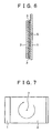
- the methods as illustrated in Figs. 7, 8, and 9 may also be used.
- the dye-sensitized wet-type solar cell is rotated about an axis 7 orthogonal to the principal surface thereof.
- the dye-sensitized wet-type solar cell is rotated about an axis 8 which equally bisects the dye-sensitized wet-type solar cell.
- Fig. 7 the dye-sensitized wet-type solar cell is rotated about an axis 7 orthogonal to the principal surface thereof.
- the dye-sensitized wet-type solar cell is rotated about an axis 8 which equally bisects the dye-sensitized wet-type solar cell.
- a single or a plurality of dye-sensitized wet-type solar cells are rotated about an axis 9 which is located outside the dye-sensitized wet-type solar cell(s), is parallel to the one end portion 4a of the electrolytic solution containing portion 4 of each dye-sensitized wet-type solar cell, and is on the same plane as the one end portion 4a.
Landscapes
- Engineering & Computer Science (AREA)
- Power Engineering (AREA)
- Microelectronics & Electronic Packaging (AREA)
- Chemical & Material Sciences (AREA)
- Chemical Kinetics & Catalysis (AREA)
- Electrochemistry (AREA)
- Health & Medical Sciences (AREA)
- Environmental & Geological Engineering (AREA)
- Structural Engineering (AREA)
- Life Sciences & Earth Sciences (AREA)
- Hydrology & Water Resources (AREA)
- Public Health (AREA)
- Water Supply & Treatment (AREA)
- Hybrid Cells (AREA)
- Photovoltaic Devices (AREA)
- Filling, Topping-Up Batteries (AREA)
Abstract
Description
Claims (13)
- A method of injecting an electrolytic solution, for injecting said electrolytic solution into an electrolytic solution containing vessel of which a portion is opened, wherein
said injection of said electrolytic solution into said electrolytic solution containing vessel is conducted by utilizing a centrifugal force. - A method of injecting an electrolytic solution as set forth in claim 1, which comprises the steps of:dropping said electrolytic solution to said opened portion of said electrolytic solution containing vessel; andapplying said centrifugal force in such a manner that at least a force in the direction from said opened portion toward the inside of said electrolytic solution containing vessel is exerted on said electrolytic solution.
- A method of injecting an electrolytic solution as set forth in claim 1, which comprises the steps of:dropping said electrolytic solution to said opened portion of said electrolytic solution containing vessel;fixing said electrolytic solution containing vessel on a turntable rotatable about a predetermined center so that said opened portion is directed inwards; androtating said turntable about said center, to thereby inject said electrolytic solution into said electrolytic solution containing vessel.
- A method of injecting an electrolytic solution as set forth in claim 1, wherein the internal size in one direction of a section of said electrolytic solution containing vessel is in the range of 1 to 200 µm.
- A method of injecting an electrolytic solution as set forth in claim 1, wherein the internal size in one direction of a section of said electrolytic solution containing vessel is in the range of 10 to 200 µm.
- A method of injecting an electrolytic solution as set forth in claim 1, wherein the internal size in one direction of a section of said electrolytic solution containing vessel is in the range of 20 to 150 µm.
- A method of injecting an electrolytic solution as set forth in claim 1, wherein said electrolytic solution has a viscosity of not more than 20 cp.
- A method of injecting an electrolytic solution as set forth in claim 1, wherein said electrolytic solution has a viscosity of not more than 10 cp.
- A method of injecting an electrolytic solution as set forth in claim 1, wherein said section of said electrolytic solution containing vessel is rectangular in shape.
- A method of manufacturing a wet-type photoelectric conversion device, comprising the step of injecting centrifugally an electrolytic solution into a vessel having at least one opening.
- A method of injecting an electrolytic solution, for injecting said electrolytic solution into a space between a semiconductor electrode comprising a semiconductor with a dye and a counter electrode opposed to said semiconductor electrode, said method comprising the steps of:injecting said electrolytic solution into at least a part of said space between said semiconductor electrode and said counter electrode, andapplying a centrifugal force to said semiconductor electrode and said counter electrode.
- A method of injecting an electrolytic solution, for injecting said electrolytic solution into a space between a semiconductor electrode comprising a semiconductor with a dye and a counter electrode opposed to said semiconductor electrode, said method comprising the steps of:injecting said electrolytic solution into at least a part of said space between said semiconductor electrode and said counter electrode, androtating said semiconductor electrode and said counter electrode.
- A method of manufacturing a wet-type apparatus, comprising the step of injecting centrifugally an electrolytic solution into a vessel having at least one opening.
Applications Claiming Priority (2)
| Application Number | Priority Date | Filing Date | Title |
|---|---|---|---|
| JP2003118472A JP2004327167A (en) | 2003-04-23 | 2003-04-23 | Method for injecting electrolyte, method for manufacturing wet photoelectric conversion element, and method for manufacturing wet device |
| JP2003118472 | 2003-04-23 |
Publications (2)
| Publication Number | Publication Date |
|---|---|
| EP1471546A2 true EP1471546A2 (en) | 2004-10-27 |
| EP1471546A3 EP1471546A3 (en) | 2007-03-14 |
Family
ID=32959630
Family Applications (1)
| Application Number | Title | Priority Date | Filing Date |
|---|---|---|---|
| EP04009443A Withdrawn EP1471546A3 (en) | 2003-04-23 | 2004-04-21 | Method of injecting an electrolytic solution to fill a photoelectrochemical cell |
Country Status (5)
| Country | Link |
|---|---|
| US (1) | US20040258980A1 (en) |
| EP (1) | EP1471546A3 (en) |
| JP (1) | JP2004327167A (en) |
| KR (1) | KR20040092457A (en) |
| CN (1) | CN100343998C (en) |
Cited By (1)
| Publication number | Priority date | Publication date | Assignee | Title |
|---|---|---|---|---|
| EP1880418A4 (en) * | 2005-05-09 | 2010-09-01 | Solaris Nanosciences Inc | Rechargeable dye sensitized solar cell |
Families Citing this family (11)
| Publication number | Priority date | Publication date | Assignee | Title |
|---|---|---|---|---|
| CN100347881C (en) * | 2005-05-25 | 2007-11-07 | 深圳市豪鹏科技有限公司 | Battery centrifugal liquid filling method using clamp |
| KR20100056552A (en) * | 2007-09-10 | 2010-05-27 | 다이솔 인더스트리즈 피티와이 엘티디 | A method for manufacturing solar cells |
| KR101032925B1 (en) | 2009-03-13 | 2011-05-06 | 주식회사 티지에너지 | Method and apparatus for manufacturing dye-sensitized solar cell |
| KR100928009B1 (en) * | 2009-05-29 | 2009-11-24 | 주식회사 티지에너지 | Intermediates of Dye-Sensitized Solar Cells and Methods of Manufacturing Dye-Sensitized Solar Cells Therefrom |
| KR101066230B1 (en) * | 2009-10-12 | 2011-09-21 | 주식회사 티지에너지 | Manufacturing method of dye-sensitized solar cell |
| KR101108186B1 (en) * | 2010-01-08 | 2012-01-31 | 삼성에스디아이 주식회사 | Photoelectric conversion module |
| US8669468B2 (en) | 2010-01-19 | 2014-03-11 | Samsung Sdi Co., Ltd. | Photoelectric conversion module |
| KR101144384B1 (en) * | 2010-09-27 | 2012-05-10 | 현대하이스코 주식회사 | Electrolyte injetion device and method for dye-sensitized solar cell |
| JP2013093176A (en) * | 2011-10-25 | 2013-05-16 | Osaka Gas Co Ltd | Electrolyte and photoelectric conversion element |
| US9698409B2 (en) | 2012-07-05 | 2017-07-04 | O.M.C. Co., Ltd. | Injection method for injecting electrolyte and injection apparatus therefor |
| CN116379611B (en) * | 2023-04-12 | 2026-04-17 | 浙江绿储科技有限公司 | An electric heating device |
Family Cites Families (21)
| Publication number | Priority date | Publication date | Assignee | Title |
|---|---|---|---|---|
| JPS59134558A (en) * | 1983-01-20 | 1984-08-02 | Matsushita Electric Ind Co Ltd | Method of injecting electrolyte into battery |
| JP2734656B2 (en) * | 1989-07-06 | 1998-04-02 | 株式会社ユアサコーポレーション | Battery |
| JP2850400B2 (en) * | 1989-09-20 | 1999-01-27 | 松下電器産業株式会社 | Lead-acid battery electrolyte injection device and injection method |
| JPH05190169A (en) * | 1992-01-10 | 1993-07-30 | Toshiba Corp | Method for stabilizing electrolytic solution in battery and apparatus used therefor |
| US5487417A (en) * | 1993-09-03 | 1996-01-30 | Toshiba Battery Co., Ltd. | Electrolyte injection apparatus |
| JP2968917B2 (en) * | 1993-09-03 | 1999-11-02 | 東芝電池株式会社 | Electrolyte injection method |
| DE19514156A1 (en) * | 1995-04-15 | 1996-10-24 | Heidelberger Druckmasch Ag | Photochemical cell |
| KR0141633B1 (en) * | 1995-07-28 | 1998-07-01 | 배순훈 | Electrolyte injection device of lithium battery |
| JP4145391B2 (en) * | 1997-06-27 | 2008-09-03 | 三井化学株式会社 | Nonaqueous electrolyte and nonaqueous electrolyte secondary battery |
| US5965054A (en) * | 1997-08-12 | 1999-10-12 | Covalent Associates, Inc. | Nonaqueous electrolyte for electrical storage devices |
| JP3724182B2 (en) * | 1998-04-14 | 2005-12-07 | 松下電器産業株式会社 | Battery electrolyte injection system |
| JP2002536805A (en) * | 1999-02-08 | 2002-10-29 | クルス グラス プラス スピーゲル アクチエンゲゼルシヤフト | Photocell and method of manufacturing the same |
| JP2000294295A (en) * | 1999-04-08 | 2000-10-20 | Hitachi Maxell Ltd | Non-aqueous electrolyte secondary battery |
| EP1087412B1 (en) * | 1999-09-24 | 2008-10-01 | Kabushiki Kaisha Toshiba | Electrolyte composition, photosensitized solar cell using said electrolyte composition, and method of manufacturing photosensitized solar cell |
| US20020039688A1 (en) * | 1999-09-29 | 2002-04-04 | Jeremy Barker | Lactone solvents for electrochemical cells |
| JP4414036B2 (en) * | 1999-12-27 | 2010-02-10 | シャープ株式会社 | Method for producing dye-sensitized solar cell |
| JP2002110113A (en) * | 2000-09-29 | 2002-04-12 | Toshiba Corp | Electronic equipment with electromagnetic shielding material and display function |
| JP2002270225A (en) * | 2001-03-09 | 2002-09-20 | Matsushita Electric Ind Co Ltd | Lithium secondary battery |
| JP3804822B2 (en) * | 2001-06-26 | 2006-08-02 | ソニー株式会社 | Display element and manufacturing method thereof |
| NL1020750C2 (en) * | 2002-06-04 | 2003-12-08 | Stichting Energie | Method and device for filling a semi-finished product for a liquid-containing photovoltaic element. |
| NL1020744C2 (en) * | 2002-06-04 | 2003-12-08 | Stichting Energie | Liquid-containing photovoltaic element. |
-
2003
- 2003-04-23 JP JP2003118472A patent/JP2004327167A/en active Pending
-
2004
- 2004-04-16 US US10/825,919 patent/US20040258980A1/en not_active Abandoned
- 2004-04-21 EP EP04009443A patent/EP1471546A3/en not_active Withdrawn
- 2004-04-22 CN CNB2004100631217A patent/CN100343998C/en not_active Expired - Fee Related
- 2004-04-22 KR KR1020040027760A patent/KR20040092457A/en not_active Ceased
Cited By (1)
| Publication number | Priority date | Publication date | Assignee | Title |
|---|---|---|---|---|
| EP1880418A4 (en) * | 2005-05-09 | 2010-09-01 | Solaris Nanosciences Inc | Rechargeable dye sensitized solar cell |
Also Published As
| Publication number | Publication date |
|---|---|
| US20040258980A1 (en) | 2004-12-23 |
| JP2004327167A (en) | 2004-11-18 |
| CN1551376A (en) | 2004-12-01 |
| KR20040092457A (en) | 2004-11-03 |
| EP1471546A3 (en) | 2007-03-14 |
| CN100343998C (en) | 2007-10-17 |
Similar Documents
| Publication | Publication Date | Title |
|---|---|---|
| de Freitas et al. | New insights into dye-sensitized solar cells with polymer electrolytes | |
| JP5023866B2 (en) | Dye-sensitized photoelectric conversion element, method for producing the same, and electronic device | |
| EP1981047B1 (en) | Photoelectric conversion device | |
| EP1075005A2 (en) | Electrolyte composition, and photo-electro-chemical cell | |
| EP1528580B2 (en) | Dye-sensitized type solar cell | |
| EP1089305B1 (en) | Electrolyte composition, photoelectric conversion device and photo-electrochemical cell | |
| EP1471546A2 (en) | Method of injecting an electrolytic solution to fill a photoelectrochemical cell | |
| US20090133746A1 (en) | Solid-State Electrolyte Composition Containing Liquid Crystal Materials and Dye-Sensitized Solar Cells Using the Same | |
| JP5267846B2 (en) | Photoelectric conversion element | |
| JP4197637B2 (en) | Photosensitized solar cell and manufacturing method thereof | |
| JP5139501B2 (en) | Electrolyte composition for dye-sensitized solar cell and dye-sensitized solar cell using the same | |
| JP5282073B2 (en) | Gel electrolyte composition, production method thereof, and dye-sensitized solar cell using the same | |
| US7763795B2 (en) | Photoelectric conversion device and method for manufacturing the same | |
| Chou et al. | The effect of various concentrations of PVDF-HFP polymer gel electrolyte for dye-sensitized solar cell | |
| JP2001035253A (en) | Electrolyte composition, photoelectric transfer element and photo-electrochemical battery | |
| JP2003297442A (en) | Photoelectric conversion oxide semiconductor electrode and dye-sensitized solar battery | |
| JP2008166119A (en) | Photoelectric conversion element | |
| KR101598687B1 (en) | A novel quasi-solid state dye-sensitized solar cell fabricated using a multifunctional network polymer membrane electrolyte | |
| WO2012138036A1 (en) | Metal oxide semiconductor electrode having porous thin film, dye-sensitized solar cell using same, and method for manufacturing same | |
| JP2001067931A (en) | Electrolyte composition, photoelectric conversion element and photoelectrochemical battery | |
| KR20150089689A (en) | Electrolyte for dye-sensitized solar cell and dye-sensitized solar cell including the same | |
| EP2631988B1 (en) | Dye-sensitized solar cell module and method for manufacturing same | |
| JP4931402B2 (en) | Photoelectric conversion element | |
| JP2010056029A (en) | Photoelectric conversion element | |
| KR101286075B1 (en) | Dye-sensitized solar cells and manufacturing methods thereof |
Legal Events
| Date | Code | Title | Description |
|---|---|---|---|
| PUAI | Public reference made under article 153(3) epc to a published international application that has entered the european phase |
Free format text: ORIGINAL CODE: 0009012 |
|
| AK | Designated contracting states |
Kind code of ref document: A2 Designated state(s): AT BE BG CH CY CZ DE DK EE ES FI FR GB GR HU IE IT LI LU MC NL PL PT RO SE SI SK TR |
|
| AX | Request for extension of the european patent |
Extension state: AL HR LT LV MK |
|
| PUAL | Search report despatched |
Free format text: ORIGINAL CODE: 0009013 |
|
| AK | Designated contracting states |
Kind code of ref document: A3 Designated state(s): AT BE BG CH CY CZ DE DK EE ES FI FR GB GR HU IE IT LI LU MC NL PL PT RO SE SI SK TR |
|
| AX | Request for extension of the european patent |
Extension state: AL HR LT LV MK |
|
| 17P | Request for examination filed |
Effective date: 20070829 |
|
| 17Q | First examination report despatched |
Effective date: 20070928 |
|
| AKX | Designation fees paid |
Designated state(s): DE FR GB |
|
| STAA | Information on the status of an ep patent application or granted ep patent |
Free format text: STATUS: THE APPLICATION IS DEEMED TO BE WITHDRAWN |
|
| 18D | Application deemed to be withdrawn |
Effective date: 20151103 |