EP1471517A2 - System and method for providing power and control signals to an element retrieval device - Google Patents
System and method for providing power and control signals to an element retrieval device Download PDFInfo
- Publication number
- EP1471517A2 EP1471517A2 EP04251262A EP04251262A EP1471517A2 EP 1471517 A2 EP1471517 A2 EP 1471517A2 EP 04251262 A EP04251262 A EP 04251262A EP 04251262 A EP04251262 A EP 04251262A EP 1471517 A2 EP1471517 A2 EP 1471517A2
- Authority
- EP
- European Patent Office
- Prior art keywords
- retrieval device
- signal
- picker
- control
- control signal
- Prior art date
- Legal status (The legal status is an assumption and is not a legal conclusion. Google has not performed a legal analysis and makes no representation as to the accuracy of the status listed.)
- Withdrawn
Links
Images



Classifications
-
- G—PHYSICS
- G11—INFORMATION STORAGE
- G11B—INFORMATION STORAGE BASED ON RELATIVE MOVEMENT BETWEEN RECORD CARRIER AND TRANSDUCER
- G11B17/00—Guiding record carriers not specifically of filamentary or web form, or of supports therefor
- G11B17/22—Guiding record carriers not specifically of filamentary or web form, or of supports therefor from random access magazine of disc records
- G11B17/228—Control systems for magazines
-
- G—PHYSICS
- G11—INFORMATION STORAGE
- G11B—INFORMATION STORAGE BASED ON RELATIVE MOVEMENT BETWEEN RECORD CARRIER AND TRANSDUCER
- G11B15/00—Driving, starting or stopping record carriers of filamentary or web form; Driving both such record carriers and heads; Guiding such record carriers or containers therefor; Control thereof; Control of operating function
- G11B15/675—Guiding containers, e.g. loading, ejecting cassettes
- G11B15/68—Automatic cassette changing arrangements; automatic tape changing arrangements
- G11B15/682—Automatic cassette changing arrangements; automatic tape changing arrangements with fixed magazines having fixed cassette storage cells, e.g. in racks
- G11B15/6835—Automatic cassette changing arrangements; automatic tape changing arrangements with fixed magazines having fixed cassette storage cells, e.g. in racks the cassettes being transferred to a fixed recorder or player using a moving carriage
-
- G—PHYSICS
- G11—INFORMATION STORAGE
- G11B—INFORMATION STORAGE BASED ON RELATIVE MOVEMENT BETWEEN RECORD CARRIER AND TRANSDUCER
- G11B17/00—Guiding record carriers not specifically of filamentary or web form, or of supports therefor
- G11B17/22—Guiding record carriers not specifically of filamentary or web form, or of supports therefor from random access magazine of disc records
- G11B17/225—Guiding record carriers not specifically of filamentary or web form, or of supports therefor from random access magazine of disc records wherein the disks are transferred from a fixed magazine to a fixed playing unit using a moving carriage
Definitions
- the present invention generally relates to element handling systems and, in particular, to a system and method for transmitting power and control signals to an element retrieval device.
- Cartridge handling systems transport movable data cartridges stored within a cartridge storage library, to various locations within the cartridge handling system in response to commands received from a host computer. Moreover, when the host computer is to read from and/or write to a data cartridge, the host computer may issue a command for retrieving the data cartridge and loading the data cartridge into a cartridge interface device accessible to the host computer.
- a cartridge handling system may employ a cartridge retrieval device that locates and retrieves the requested data cartridge from the cartridge storage library.
- the cartridge retrieval device normally comprises a "picker" for grabbing the requested data cartridge and removing the data cartridge from the cartridge storage library, After utilizing the picker to retrieve the requested data cartridge, the cartridge retrieval device transports the cartridge to the cartridge interface device and again utilizes the picker to load the cartridge into the cartridge interface device.
- the host computer then utilizes the cartridge interface device to read from and/or write to the loaded data cartridge. Once the host computer no longer needs access to the data cartridge, the host computer issues a command for returning the data cartridge to the cartridge storage library. In response to such a command, the cartridge retrieval device retrieves the cartridge from the cartridge interface device and transports the cartridge back to the cartridge storage library.
- Control signals for instructing a cartridge retrieval device to retrieve and move cartridges, as described above, and/or a power signal for providing the cartridge retrieval device with power are typically transmitted to the cartridge retrieval device via one or more wires coupled to the cartridge retrieval device.
- the foregoing wires can become entangled with the cartridge retrieval device causing the cartridge retrieval device to malfunction. Further, such wires are typically flexed or bent when the cartridge retrieval device moves, thereby causing the wires to fatigue and eventually fail.
- the aforementioned power and control wires are sometimes eliminated from the design of the cartridge handling system.
- the power wires may be eliminated by installing a battery on the cartridge retrieval device or by transmitting a power signal to the cartridge retrieval device over conductive track members that may also be used to guide the cartridge retrieval device.
- the control wires may be eliminated by wirelessly transmitting the control signals to the cartridge retrieval device.
- U.S. Patent No. 5,303,214 discloses the use of infrared signals to communicate the control signals to a wireless receiver residing on the cartridge retrieval device.
- ensuring that such a wireless receiver is correctly positioned for receiving the wireless control signals may be problematic, particularly for cartridge retrieval devices capable of moving in at least two dimensions.
- the present invention pertains to systems and and methods for transmitting power and control signals to an element retrieval device.
- One embodiment of the present invention is an element handling system comprising an element retrieval device and a decoder.
- the element retrieval device is configured to retrieve and transport a movable element in response to control data.
- the decoder is coupled to the element retrieval device.
- the decoder is configured to filter a combined power and control signal to recover an encoded radio frequency (RF) control signal.
- the decoder is further configured to decode the RF control signal to recover the control data.
- RF radio frequency
- Another embodiment is an element handling system comprising an element retrieval device and a ceramic filter.
- the element retrieval device is configured to retrieve and transport a movable element in response to control data.
- the ceramic filter is coupled to the element retrieval device.
- the ceramic filter is configured to filter a combined power and control signal thereby recovering the control signal that comprises the control data.
- a further method in accordance with an exemplary embodiment of the present invention comprises encoding a radio frequency (RF) signal with control data, combining the encoded RF signal with a power signal thereby forming a combined power and control signal, retrieving and transporting a movable element via an element retrieval device in response to the control data, transmitting the combined power and control signal to the element retrieval device, filtering the power and control signal thereby recovering the encoded RF signal, and decoding the recovered encoded RF signal thereby recovering the control data.
- RF radio frequency
- a method in accordance with another exemplary embodiment of the present invention comprises transmitting a combined power and control signal to an element retrieval device, and filtering, via a ceramic filter, the combined power and control signal, thereby recovering a control signal, the control signal comprising the control data.
- FIG. 1 is a block diagram illustrating an exemplary embodiment of an element handling system in accordance with the present invention.
- FIG. 2 is a block diagram illustrating an exemplary embodiment of an element retrieval device, such as is depicted in FIG. 1.
- FIG. 3 is a block diagram illustrating an element retrieval device, such as is depicted in FIG. 2.
- FIG. 4 is a block diagram illustrating a top view of an element handling system, such as is depicted in FIG. 1.
- FIG. 5 is a diagram illustrating a cross-sectional view of upper and lower track members depicted in FIG. 4.
- FIG. 6 is a block diagram illustrating a side view of an element retrieval device and, as well as upper and lower track members, such as is depicted in FIG. 4.
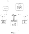
- FIG. 7 is a block diagram illustrating a system manager, such as is depicted in FIG. 1.
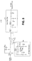
- FIG. 8 is a circuit diagram illustrating an encoder, such as is depicted in FIG. 7.
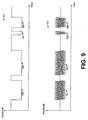
- FIG. 9 is a diagram illustrating an exemplary control signal that may be input into the encoder of FIG. 8 and a corresponding output of the encoder.
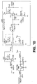
- FIG. 10 is a circuit diagram illustrating a decoder, such as is depicted in FIG. 2.
- FIG. 11 is a block diagram illustrating another exemplary embodiment of a element retrieval device, such as is depicted in FIG. 1.
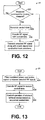
- FIG. 12 is a flow chart illustrating an exemplary architecture and functionality of a system manager, such as is depicted in FIG. 1.
- FIG. 13 is a flow chart illustrating an exemplary architecture and functionality of an element retrieval device, such as is depicted in FIG. 1
- An element handling system in accordance with an exemplary embodiment of the present invention utilizes an element retrieval device for retrieving and transporting movable elements within the element handling system.
- the element retrieval device in such an embodiment, is preferably coupled to at least one track member that is utilized to provide the element retrieval device with a power signal.
- a signal may be encoded with the control data.
- the encoded signal may then be combined with the power signal before the power signal is transmitted to the element retrieval device.
- a filter on board the element retrieval device then preferably filters the combined signal in order to recover the encoded signal, and a decoder preferably decodes this signal to recover the control data.
- the recovered control data may then be used to control the operation of the element retrieval device.
- FIG. 1 depicts a element handling system 20 in accordance with an exemplary embodiment of the present invention.
- the system 20 preferably comprises an element holding apparatus 22 for storing a plurality of movable elements 25.
- each of the elements 25 may comprise a data element, such as a memory disc, for example.
- each of the elements 25 comprises a data cartridge, and the system 20 will be described as a system for handling data cartridges.
- each of the elements 25 may comprise other types of devices, and the term "element" should not be construed as being limited to data cartridges only.
- the element handling system 20 may be employed within a medical research facility, and each element 25 may comprise a vial of a substance that is under research.
- the system 20 may handle and transport various types of elements.
- the system 20 of FIG. 1 preferably comprises a movable element retrieval device 30 for retrieving and transporting at least one of the elements 25 according to control signals received from a system manager 34.
- the system manager 34 may receive, from a host computer system 37, a command requesting access to one of the elements 25 identified by the command.
- the system manager 34 may transmit, to the element retrieval device 30, control data instructing the device 30 to retrieve the identified element 25 and to load the identified element 25 into an element interface device 39 that may be utilized by the host computer system 37 for writing to and/or reading from elements 25 loaded into the element interface device 39.
- the system manager 34 may be implemented in hardware, software, or a combination thereof.
- the element retrieval device 30 moves to a position such that a picker 45 (FIG. 2) may retrieve the identified element 25 from the element holding apparatus 22.
- the picker 45 may be any known or future-developed device capable of removing elements 25 from and/or loading elements 25 to the element holding apparatus 22 or other element storage component (e.g., element interface device 39).
- the element retrieval device 30 comprises control logic 52 for generally controlling the operation of the device 30, and the element retrieval device 30 comprises a motor 54, operating generally under the direction and control of the logic 52, for moving the device 30 in a horizontal direction to and from the element holding apparatus 22 and the element interface device 39.
- the picker 45 comprises an elevator 58 for moving the picker 45 in a vertical direction that is substantially perpendicular to the horizontal direction of movement enabled by the motor 54. Note that the elevator 58 is optional, and it is not necessary for the picker 45 to employ an elevator 58 in other embodiments.
- the control logic 52 can be implemented in software, hardware, or any combination thereof. In an exemplary embodiment depicted by FIG. 3, the control logic 52, along with its associated methodology, is implemented in software and stored in memory 61 of the element retrieval device 30.
- control logic 52 when implemented in software, can be stored and transported on any computer-readable medium for use by or in connection with an instruction execution system, apparatus, or device, such as a computer-based system, processor-containing system, or other system that can fetch and execute instructions.
- a "computer-readable medium” can be any means that can contain, store, communicate, propagate, or transport a program for use by or in connection with the instruction execution system, apparatus, or device.
- the computer readable-medium can be, for example but not limited to, an electronic, magnetic, optical, electromagnetic, infrared, or semiconductor system, apparatus, device, or propagation medium.
- the computer-readable medium could even be paper or another suitable medium upon which the program is printed, as the program can be electronically captured, via for instance optical scanning of the paper or other medium, then compiled, interpreted or otherwise processed in a suitable manner if necessary, and then stored in a computer memory.
- the control logic 52 may be magnetically stored and transported on a conventional portable computer diskette.
- the element retrieval device 30 comprises at least one conventional processing element 63, such as a digital signal processor (DSP) or a central processing unit (CPU), that communicate to and drive the other elements within the device 30 via a local interface 65, which can include at least one bus.
- DSP digital signal processor
- CPU central processing unit
- the processing element 63 may be utilized to execute instructions defined by the control logic 52.
- the control logic 52 (FIG. 2) preferably controls the motor 54 and the elevator 58 such that the picker 45 is moved to a position adjacent to the identified element 25.
- the control logic 52 then instructs the picker 45 to retrieve the identified element 25.
- the picker 45 grasps the identified element 25 and removes the identified element from the element holding apparatus 22.
- the control logic 52 may then control the motor 54 such that the element 25 is carried to the element interface device 39 by the element retrieval device 30.
- the control logic 52 may then instruct the picker 45 to load the element 25 into the element interface device 39.
- the picker 45 preferably inserts the element 25 into the device 39 and then releases the element 25.
- the host computer system 37 may utilize the element interface device 39 to access the loaded element 25.
- the host computer system 37 may transmit, to the system manager 34, a command requesting that the previously loaded element 25 be returned to the holding apparatus 22.
- the system manager 34 preferably transmits, to the element retrieval device 30, control data instructing the device 30 to return the element 25 to the holding apparatus 22.
- the control logic 52 of the device 30 controls the motor 54 and the picker 45, including the picker's elevator 58, such that the device 30 retrieves the element 25 from the element interface device 39 and transports the element 25 to the holding apparatus 22.
- the control logic 52 then controls the picker 45 such that the picker 45 loads the elements 25 into the holding apparatus 22 and then releases the element 25.
- the element 25 may be returned to the same position in the holding apparatus 22 from where it was originally retrieved, or the element retrieval device 30 may load the element 25 into a different position within the holding apparatus 22.
- the element handling system 20 comprises at least one conductive track member that may be utilized to guide the element retrieval device 30 as it moves through the system 20.
- FIGS. 4 and 5 depict an exemplary embodiment where the system 20 comprises U-shaped upper and lower conductive track members 81 and 82 that guide the element retrieval device (ERD) 30 as it moves from the element holding apparatus 22 to the element interface device 39 and vice versa.
- the element holding apparatus (EHA) 22 comprises multiple components 85-87, each of which preferably stores a plurality of elements 25.
- the track members 81 and 82 it is not necessary for the track members 81 and 82 to be U-shaped, and other types of shapes for the track members 81 and 82 are possible in other embodiments.
- the element retrieval device 30 comprises a conductive engaging member 95 that extends into the groove 91 of the upper track member 81 and that slides across an inner surface 96 within the groove 91.
- the element retrieval device 30 may comprise a spring (not shown) for pressing the member 95 against the inner surface 96 such that conductive contact between the conductive track member 81 and the conductive engaging member 95 is substantially maintained as the device 30 moves.
- the inner track member walls defining the groove 91 preferably act as a guide for guiding the conductive engaging member 95 and, therefore, the element retrieval device 30 along the length of the track member 81 as the device 30 moves.
- the element retrieval device 30 also comprises a conductive engaging member 97 that extends into the groove 92 of the lower track member 82 and that slides across an inner surface 99 within the groove 92.
- the element retrieval device 30 may comprise a spring (not shown) for pressing the member 97 against the inner surface 99 such that conductive contact between the track member 82 and the conductive engaging member 97 is substantially maintained as the device 30 moves.
- the inner track member walls defining the groove 92 preferably act as a guide for guiding the conductive engaging member 97 and, therefore, the element retrieval device 30 along the length of the track member 82 as the device 30 moves.
- a combined power and control signal is provided to the element retrieval device 30 over the track members 81 and 82.
- the system manager 34 is preferably coupled to each of the conductive track members 81 and 82 and is preferably configured to transmit a power signal over the conductive track members 81 and 82.
- one of the track members 81 or 82 may be driven to a first voltage (eg., ground) by the manager 34, and the other track member 81 or 82 may be driven to a different voltage by the manager 34. Therefore, the element retrieval device 30, via conductive engaging members 81 and 82, is able to draw power from the voltage difference existing across the conductive track members 81 and 82.
- the system manager 34 is configured to maintain approximately a 12 Volt (V) difference between the conductive track members 81 and 82, although other voltage differentials may be maintained in other embodiments.
- V 12 Volt
- the manager 34 when the manager 34 is to transmit control data to the element retrieval device 30, the manager 34 preferably encodes a high-frequency signal, such as a radio frequency (RF) signal, for example, with the control data and combines the encoded high-frequency signal with the power signal before transmitting the power signal across the track members 81 and 82.
- RF radio frequency
- This combined signal is preferably received by the element retrieval device 30 via the conductive engaging members 95 and 97 (FIG. 6), and a power bus 105 (FIG. 2) residing on the element retrieval device 30 distributes power from the combined signal to the other components of the device 30.
- a decoder 108 residing on the element retrieval device 30 preferably receives the combined signal, and a filter 110 of the decoder 108 preferably receives and filters the combined signal in order to recover the encoded high-frequency signal.
- the decoder 108 may then decode the recovered high-frequency signal in order to recover the control data originally encoded on the high-frequency signal by the system manager 34.
- the control logic 52 then preferably controls the operation of the device 30 based on the control data.
- the track members 81 and/or 82 may be a noisy transmission medium for the control data, particularly when the control data is combined with a power signal before being transmitted over the track members 81 and/or 82, as described above. Indeed, the noise present on the track members 81 and/or 82 and the noise induced by the power signal may make recovery of the control data at the element retrieval device 30 problematic in some embodiments.
- the high-frequency signal utilized to encode the control data is preferably an RF signal
- the filter 110 utilized in recovering the control data preferably comprises a ceramic filter, which is a high-performance filter often utilized to recover RF transmissions.
- ceramic filters for recovering RF signals at approximately 10.7 Mega-Hertz (MHz) are widely available for use in current RF communication and may be employed in order to recover the encoded high-frequency signal, as described above.
- FIG. 7 depicts an exemplary embodiment of a system manager 34 that is configured to combine an encoded RF frequency signal with a power signal and to transmit the combined RF and power signal over the track members 81 and 82, as described above.
- the system manager 34 preferably comprises control logic 124 that is configured to control the operation of the manager 34.
- the control logic 124 can be implemented in software, hardware, or any combination thereof. In the exemplary embodiment depicted by FIG. 7, the control logic 124, along with its associated methodology, is implemented in software and stored in memory 127.
- the manager 34 may also comprise at least one conventional processing element 131, such as a digital signal processor (DSP) or a central processing unit (CPU), that communicate to and drive the other elements within the manager 34 via a local interface 133, which can include at least one bus. As shown by FIG. 7, the manager 34 may also comprise a data port 138 for communicating with the host computer system 37 (FIG. 1).
- DSP digital signal processor
- CPU central processing unit
- a signal combiner 142 is preferably employed to combine encoded control data with a power signal.
- the control logic 124 may generate or otherwise provide control data that is to be communicated to the element retrieval device 30 (FIG. 1).
- the signal combiner 142 preferably receives this control data, and an encoder 152 of the signal combiner 142 may encode this data onto an RF signal preferably transmitting at approximately 10.7 MHz.
- the signal combiner 142 may then combine the encoded RF signal with a power signal received from a power source 145, such as a battery or generator, for example.
- the signal combiner 142 combines the RF and power signals by transmitting over at least one of the track members 81 or 82 the power signal along with the RF signal that is encoded with the control data.
- FIG. 8 depicts an exemplary embodiment of an encoder 152 that may be employed by the signal combiner 142 to encode an RF signal with control data in accordance with the preferred embodiment.
- a NAND gate 161 receives a control signal comprising control data from the control logic 124 (FIG. 7) and biases the control signal with respect to a reference voltage (V ref ), such as 5 Volts, for example.
- V ref a reference voltage
- an RF signal generator 166 having a crystal 168 generates an RF signal.
- the crystal 168 generates an RF signal at approximately 10.7 MHz, although other frequencies are possible in other embodiments.
- the RF signal generated by the signal generator 166 is then encoded with the control data of the biased control signal by NAND gates 171 and 172.
- This encoded signal referred to hereafter as the "encoded control signal” is then transmitted across one of the track members 81 or 82 along with the power signal received from the power source 145 (FIG. 7).
- the encoded signal is preferably passed through a band-pass filter 175 before being transmitted across one of the track members 81 or 82.
- the band-pass filter 175 preferably filters out signals having frequencies different than the frequency of the signal generated by the signal generator 166.
- the encoded control signal is allowed to pass, and noise outside of the frequency band of the signal generator 166 is filtered.
- the resistance and capacitance values depicted in FIG. 8 are sufficient for enabling an encoded control signal of 10.7 MHz to be generated and filtered. However, in other embodiments, other resistance and capacitance values are possible in order to generate an encoded control signal of 10.7 MHz or some other frequency.
- FIG. 9 depicts an exemplary digital control signal 181 before being passed through the encoder 152 and the corresponding output signal 183 of the encoder 152 that is produced by encoding the control signal 183 onto an RF signal.
- FIG. 9 depicts an exemplary digital control signal 181 before being passed through the encoder 152 and the corresponding output signal 183 of the encoder 152 that is produced by encoding the control signal 183 onto an RF signal.
- each of the logical low portions 185-188 of the control signal 181 are converted, by the encoder 152, into high frequency bursts 191-194, respectively.
- the decoder's filter 110 preferably filters the combined signal to recover the RF signal that is encoded with the control data.
- the filter 110 of the element retrieval device 30 is tuned to 10.7 MHz such that frequencies other than approximately 10.7 MHz are filtered out.
- the decoder 108 then decodes the filtered signal in order to recover the original control data of the control signal received by the signal combiner 142 (FIG. 7). It should be noted that frequencies other than 10.7 MHz may be employed to transmit the control data.
- the filter 110 is preferably tuned to the frequency of the control signal generated by the system manager 34 such that the control data is recovered by the decoder 108.
- FIG. 10 depicts an exemplary embodiment of a decoder 108 that may be utilized to filter and decode the combined signal received from track member 81 or 82.
- a filter 110 which is preferably a ceramic filter tuned to 10.7 MHz, receives and filters the combined signal in order to recover the encoded RF signal originally output by the encoder 152 of the system manager 34. This filtered RF signal is then biased by amplifier 202 with respect to V ref .
- the biased signal is then passed through a signal comparator 205 that recovers the control data originally utilized to encode the RF signal generated by the encoder 152.
- the filtered RF signal is amplified by an amplifier 211 and then peak detected via diode 214.
- the signal output by the diode 214 is then compared to V ref by amplifier 217 and amplified.
- the signal output by the amplifier 217 preferably represents the control signal originally received by the encoder 152 of the system manager 34.
- the control signal decoded by the decoder 108 is preferably transmitted to the control logic 52, which preferably utilizes the control data defined by this signal to control the operation of the element retrieval device 30.
- the data defined by the decoded control signal may indicate that a particular element 25 is to be retrieved and moved to another location within the element handling system 20.
- the control logic 52 may control the motor 54 and the picker 45 such that the requested operation is performed by the element retrieval device 30.
- encoding and/or decoding of control data may occur at any time relative to the motion or action of the element retrieval device 30.
- a new command may be transmitted to and decoded by the element retrieval device 30 before, during, or after execution of a previous command by the element retrieval device 30.
- the new command it is possible for the new command to be encoded and transmitted by the system manager 34 and/or to be received and decoded by the element retrieval device 30 while the element retrieval device 30 is moving along the track members 91 and 92 and/or while the picker 45 is otherwise handling an element 25.
- picker control logic 250 for controlling the operation of the picker 45 based on control data from the system manager 34 may be implemented separate from the control logic 52 and may reside on or near the picker 45.
- the picker control logic 250 is implemented in hardware in an effort to simplify the picker's circuitry.
- the picker control logic 250 may be implemented in software or a combination of software and hardware.
- the picker 45 may comprise a decoder 252 and filter 254 for recovering control signals transmitted from the system manager 34 according to the same techniques employed by decoder 108 and filter 110 described hereinabove. Further, the picker 45 may also comprise a picker power bus 255 for receiving the power signal transmitted over track members 81 and 82 and for providing power from this signal to the other components of the picker 45.
- the picker 45 preferably moves with respect to other components (e.g., decoder 108, motor 54, etc . ) of the element retrieval device 30.
- providing both power and control data to the picker 45 via a combined signal eliminates the need of coupling one or more wires between the picker 45 and the other components of the device 34, thereby reducing the risk that the picker 45 will become entangled and malfunction.
- eliminating the utilization of wires between the picker 45 and the other components of the device 34 eliminates errors that may occur due to fatigue and/or failure of such wires.
- the encoded control data transmitted over the track members 81 and/or 82 may comprise data destined for control logic 52 and data destined for picker control logic 250.
- the system manager 34 may be configured to insert headers or other types of tags into the control data being transmitted to the element retrieval device 30. More specifically, each byte of control data transmitted by the signal combiner 152 may be associated with a header indicating whether the byte of data is destined for the control logic 52 or is destined for the picker control logic 250.
- control data to be utilized by the control logic 52 for controlling the non-picker operations of the device 30 is preferably associated with a header identifying the control logic 52
- control data to be utilized by the picker control logic 45 for controlling the operation of the picker 45 is preferably associated with a header identifying the picker control logic 250.
- control logic 52 upon receiving a byte of control data from decoder 108, preferably analyzes the associated header in order to determine whether or not the byte is destined for the control logic 52. If the byte of data is destined for the control logic 52, then the control logic 52 reads the byte of data and controls operation of the device 30 based on the byte of data. However, if the byte of data is not destined for the control logic 52, then the control logic 52 may ignore the byte of data.
- the picker control logic 250 upon receiving a byte of control data from decoder 252, preferably analyzes the associated header in order to determine whether or not the byte is destined for the picker control logic 250. If the byte of data is destined for the picker control logic 250, then the picker control logic 250 reads the byte of data and controls operation of the picker 45 based on the byte of data- However, if the byte of data is not destined for the picker control logic 250, then the picker control logic 250 may ignore the byte of data.
- the elevator 58 may be controlled via pulse width modulation (PWM), if desired.
- PWM pulse width modulation
- the system manager 34 may be configured to control the elevator 58 by transmitting the proper PWM values for causing the elevator 58 to perform a desired task.
- the picker control logic 250 may be configured to simply pass the PWM values to the elevator 58. Thus, it is not necessary for the picker control logic 250 to actually determine the PWM values to be provided to the elevator 58, thereby helping to simplify and minimize the amount of circuitry necessary for implementing the picker control logic 250.
- control logic 52 or the picker control logic 250 may determine the PWM values to be provided to the elevator 58 based on instructions from the system manager 34. Further, if motor 54 (FIG. 2) is controlled via pulse width modulation, PWM values may be similarly transmitted to the motor 54 via the system manager 34 and/or the control logic 52.
- the element retrieval device 30 may comprise an encoder 263 that may be utilized by the picker control logic 250 to transmit signals to the system manager 34.
- the picker control logic 250 may transmit an acknowledgement of any request successfully received by the logic 250.
- the picker control logic 250 may transmit, to the manager 34, data indicative of the completed task.
- the logic 250 may be configured to transmit successfully received PWM values back to the manager 34 such that the manager 34 can verify that the correct PWM values have been provided to the elevator 58.
- the configuration and operation of the encoder 263 may be similar to that of the encoder 152 (FIG. 2) of the system manager 34 previously described hereinabove.
- the system manager 34 may comprise a decoder (not specifically shown) for receiving and recovering the data transmitted to it from the element retrieval device 30.
- the encoded signals transmitted by the system manager 34 may be at a frequency different than the frequency of the encoded signals transmitted by the element retrieval device 30.
- the data transmitted by the system manager 34 may be passed over one of the track members 81 or 82, and the data transmitted by the element retrieval device 30 may be passed over the other of the track members 81 or 82.
- the element retrieval device 30 may comprise an encoder (not shown), similar to the picker encoder 263 of FIG. 11, to enable the control logic 52 to transmit messages (e.g., acknowledgements) to the system manager 34.
- the system manager 34 receives, from the host computer system 37 (FIG. 1), a command for moving an element 25 from one location (e.g., holding apparatus 22) within the element handling system 20 to another location (e.g., element interface device 39) within the element handling system 20.
- the system manager 34 generates control data for instructing the element retrieval device 30 to perform the commanded task, as shown by blocks 301 and 305 of FIG. 12. If the control logic 52 and picker control logic 250 are implemented separately, as shown by FIG.
- the system manager 34 may associate each byte of control data for controlling the picker 45 with a first type of header, referred to hereafter as a "picker header,” and the system manager 34 may associate each byte of control data for controlling the other components of the device 30 with a second type of header, referred to hereafter as a ''non-picker header.”
- the system manager 34 After generating the control data in block 305, the system manager 34 then encodes an RF signal with the control data, as shown by block 308. This encoded RF signal is then transmitted over at least one of the track members 81 and/or 82 along with a power signal from the power source 145 (FIG. 7), as shown by block 312 of FIG. 12, thereby communicating a combined power and control signal over the track members 81 and/or 82.
- the power signal is preferably continuously transmitted over the track members 81 and 82 regardless of whether there is any control data that is to be transmitted to the element retrieval device 30. Therefore, the device 30 is continuously provided with power even during periods when no control data is transmitted to the element retrieval device 30.
- the element retrieval device 30 Upon receiving the combined power and control signal, the element retrieval device 30 filters the combined power and control signal to recover the aforedescribed encoded RF signal, as shown by block 325 of FIG. 13.
- a ceramic filter 110 is employed to recover the encoded RF signal.
- the decoder 108 of the element retrieval device 30 then decodes, in block 328, the recovered RF signal in order to recover the control data previously generated by the system manager 34 in block 305 of FIG. 12.
- a ceramic filter 254 recovers the encoded RF signal
- the decoder 252 recovers the control data previously generated by the system manager 34 in block 305 of FIG. 12.
- the control logic 52 and/or the picker control logic 250 preferably utilize the recovered control data in order to cause the element retrieval device 30 to perform the instructed task, as depicted by block 332.
- control logic 52 may ignore each byte of the control data associated with a picker header and may utilize the remainder of the control data to control the operation of the element retrieval device 30 (e.g., to control operation of the motor 54).
- picker control logic 250 may ignore each byte of the control data associated with a non-picker header and may utilize the remainder of the control data to control the operation of the picker 45.
- the element retrieval device 30 may be efficiently and reliably provided with both power and control data via the conductive track members 81 and 82.
Landscapes
- Warehouses Or Storage Devices (AREA)
- Selective Calling Equipment (AREA)
Abstract
Description
Claims (10)
- An element handling system (20), comprising:an element retrieval device (30) configured to retrieve and transport a movable element (25) in response to control data; anda ceramic filter (110) coupled to the element retrieval device, the ceramic filter configured to filter a combined power and control signal thereby recovering the control signal, the control signal comprising the control data.
- The system of claim 1, wherein the control signal comprises an encoded radio frequency (RF) signal, and wherein the system further comprises a decoder (108) configured to decode the recovered control signal, thereby recovering the control data.
- The system of claim 1, wherein the element retrieval device comprises a picker (45) configured to retrieve the element based on a portion of the control data, and wherein the system further comprises a ceramic filter (254) coupled to the picker, the picker ceramic filter configured to filter the power signal from the control signal thereby recovering the control signal.
- The system of claim 1, wherein the element retrieval device comprises a picker (45), and wherein at least one byte of the control data is associated with a tag indicating whether the at least one byte is for controlling the picker.
- The system of claim 1, wherein the element retrieval device has a conductive member (95, 97) that slides along a surface of at least one conductive track member (81, 82) as the element retrieval device moves; wherein the ceramic filter is configured to receive the combined power and control signal from the conductive member of the element retrieval device.
- The system of claim 1, wherein the element retrieval device comprises a picker and picker control logic, wherein at least one byte of the control data comprises a pulse width modulation (PWM) value, and wherein the picker control logic is configured to provide the PWM value to an elevator; and wherein the picker control logic is further configured to cause an encoder to encode a second RF signal with the PWM value and to transmit the second encoded RF signal to the system manager.
- A method for use in an element handling system (20), comprising:transmitting a combined power and control signal to an element retrieval device (30); andfiltering, via a ceramic filter (110), the combined power and control signal thereby recovering a control signal, the control signal comprising the control data.
- The method of claim 7, wherein the control signal comprises an encoded radio frequency (RF) signal, and wherein the method further comprises decoding the recovered control signal thereby recovering the control data.
- The method of claim 7, further comprising:removing, based on a portion of the control data, a movable element (25) from an element holding apparatus (22) via a picker (45) coupled to the element retrieval device; andfiltering, via a second ceramic filter (254) coupled to the picker, the power signal from the control signal thereby recovering the control signal.
- The method of claim 7, further comprising:wherein the transmitting comprises transmitting the combined power and control signal over the at least one conductive track member.retrieving and transporting a movable element (25) via the element retrieval device in response to control data;moving the element retrieval device across a surface of at least one conductive track member (81, 82) during the transporting,
Applications Claiming Priority (2)
| Application Number | Priority Date | Filing Date | Title |
|---|---|---|---|
| US10/421,520 US6957124B2 (en) | 2003-04-23 | 2003-04-23 | System and method for providing power and control signals to an element retrieval device |
| US421520 | 2003-04-23 |
Publications (2)
| Publication Number | Publication Date |
|---|---|
| EP1471517A2 true EP1471517A2 (en) | 2004-10-27 |
| EP1471517A3 EP1471517A3 (en) | 2005-12-14 |
Family
ID=32962429
Family Applications (1)
| Application Number | Title | Priority Date | Filing Date |
|---|---|---|---|
| EP04251262A Withdrawn EP1471517A3 (en) | 2003-04-23 | 2004-03-04 | System and method for providing power and control signals to an element retrieval device |
Country Status (2)
| Country | Link |
|---|---|
| US (1) | US6957124B2 (en) |
| EP (1) | EP1471517A3 (en) |
Families Citing this family (1)
| Publication number | Priority date | Publication date | Assignee | Title |
|---|---|---|---|---|
| JP2011150761A (en) * | 2010-01-22 | 2011-08-04 | Fujitsu Ltd | Library device |
Family Cites Families (15)
| Publication number | Priority date | Publication date | Assignee | Title |
|---|---|---|---|---|
| US3881053A (en) * | 1955-06-14 | 1975-04-29 | Jerome H Lemelson | Scanning system |
| JPS5698726A (en) * | 1980-01-08 | 1981-08-08 | Hitachi Ltd | Information reproducing device |
| US5773939A (en) * | 1984-11-16 | 1998-06-30 | Severson; Frederick E. | Command control for model railroading using AC track power signals for encoding pseudo-digital signals |
| US5057758A (en) * | 1989-03-20 | 1991-10-15 | Hewlett-Packard Company | Passive payload for a cartridge handling system |
| US5303214A (en) | 1992-01-03 | 1994-04-12 | International Business Machines Corporation | Multi-media-type automatic libraries |
| JPH0684251A (en) | 1992-02-25 | 1994-03-25 | Internatl Business Mach Corp <Ibm> | Automatic storage library |
| US5940356A (en) | 1994-12-16 | 1999-08-17 | Toumbas; Christos | Modular compact disk filing system with automatic disk selection and playing, which permits modular expansion in all three dimensions |
| DE69626457T2 (en) | 1995-10-09 | 2003-10-02 | Fuji Photo Film Co., Ltd. | Transport device and transport method |
| US5886619A (en) * | 1996-04-19 | 1999-03-23 | Kabushiki Kaisha Toyoda Jidoshokki Seisakusho | Communication method in movable body operating system |
| US6175539B1 (en) | 1998-08-28 | 2001-01-16 | Hewlett-Packard Co. | System and method for providing wireless control signals to cartridge access device in a cartridge storage system |
| US6490122B1 (en) * | 1998-08-28 | 2002-12-03 | Hewlett-Packard Company | System and method for providing power and control signals to a cartridge access device in a cartridge storage system |
| US6457681B1 (en) * | 2000-12-07 | 2002-10-01 | Mike's Train House, Inc. | Control, sound, and operating system for model trains |
| US6751048B2 (en) * | 2001-06-29 | 2004-06-15 | Storage Technology Corporation | Power rail distribution system and method for an automated robotic device in a data storage system |
| US6668991B2 (en) * | 2001-06-29 | 2003-12-30 | Sebastian Canaday | Redundant power supply system and method for an automated robotic device in a data storage system |
| US6698359B1 (en) * | 2002-10-07 | 2004-03-02 | Storage Technology Corporation | Data storage library rail anomaly recovery |
-
2003
- 2003-04-23 US US10/421,520 patent/US6957124B2/en not_active Expired - Fee Related
-
2004
- 2004-03-04 EP EP04251262A patent/EP1471517A3/en not_active Withdrawn
Also Published As
| Publication number | Publication date |
|---|---|
| US20040215366A1 (en) | 2004-10-28 |
| US6957124B2 (en) | 2005-10-18 |
| EP1471517A3 (en) | 2005-12-14 |
Similar Documents
| Publication | Publication Date | Title |
|---|---|---|
| US8037346B2 (en) | Avoiding a part of tape where error occurs by computing a number of records and a number of boundary marks included in an error data unit | |
| WO2002019706A8 (en) | Video recording system utilizing storage redundancy to transfer error-intolerant data while transferring error-tolerant data | |
| JP2006331643A (en) | Cartridge shifter | |
| US7475205B2 (en) | System for inventory control of an automated data storage library | |
| US8638521B2 (en) | Shingled recording apparatus and method capable of detecting drifted-off writing | |
| US6957124B2 (en) | System and method for providing power and control signals to an element retrieval device | |
| CN1956089B (en) | Automatic data storage library and automaton communication system | |
| US9737993B2 (en) | Tape library apparatus and information management method | |
| US9454988B2 (en) | Tape storage device | |
| CN103021431B (en) | Data library device, data archive system, server | |
| US9417237B2 (en) | Biosample plate with data storage and wireless communication means | |
| US8041916B2 (en) | Data storage device and method of operating the same | |
| US20090180212A1 (en) | Apparatus and method for writing and reading data to and from tape medium | |
| US10635314B2 (en) | Write procedure using estimated best setting in first run | |
| US9613036B2 (en) | Magnetic tape drive apparatus, magnetic tape drive system, and magnetic tape drive method | |
| JP4985239B2 (en) | RF tag system, RF tag and tag reader | |
| US8982489B1 (en) | Pseudo-differential magnetic recording system and method incorporating a dummy read element and a dummy transmission line | |
| US10255944B2 (en) | Systems and methods for reading and decoding encoded data from a storage device | |
| US7779200B2 (en) | Method and apparatus for a magnetic tape storage system to adaptively handle space commands | |
| US9564160B1 (en) | Servo compensation control in a vibration environment | |
| CN119018540A (en) | Handling system | |
| JP2008287537A (en) | Production management system | |
| JP2007179694A (en) | Library apparatus and recording medium management method | |
| GB2410605A (en) | Write once read many tape drive | |
| JP2016197356A (en) | Data archive system and data archive method |
Legal Events
| Date | Code | Title | Description |
|---|---|---|---|
| PUAI | Public reference made under article 153(3) epc to a published international application that has entered the european phase |
Free format text: ORIGINAL CODE: 0009012 |
|
| AK | Designated contracting states |
Kind code of ref document: A2 Designated state(s): AT BE BG CH CY CZ DE DK EE ES FI FR GB GR HU IE IT LI LU MC NL PL PT RO SE SI SK TR |
|
| AX | Request for extension of the european patent |
Extension state: AL HR LT LV MK |
|
| PUAL | Search report despatched |
Free format text: ORIGINAL CODE: 0009013 |
|
| AK | Designated contracting states |
Kind code of ref document: A3 Designated state(s): AT BE BG CH CY CZ DE DK EE ES FI FR GB GR HU IE IT LI LU MC NL PL PT RO SE SI SK TR |
|
| AX | Request for extension of the european patent |
Extension state: AL LT LV MK |
|
| RIC1 | Information provided on ipc code assigned before grant |
Ipc: 7G 11B 17/22 B Ipc: 7G 11B 15/68 A |
|
| AKX | Designation fees paid | ||
| REG | Reference to a national code |
Ref country code: DE Ref legal event code: 8566 |
|
| STAA | Information on the status of an ep patent application or granted ep patent |
Free format text: STATUS: THE APPLICATION IS DEEMED TO BE WITHDRAWN |
|
| 18D | Application deemed to be withdrawn |
Effective date: 20060615 |