EP1471310A1 - Air conditioner - Google Patents

Air conditioner Download PDF

Info

Publication number
EP1471310A1
EP1471310A1 EP02738810A EP02738810A EP1471310A1 EP 1471310 A1 EP1471310 A1 EP 1471310A1 EP 02738810 A EP02738810 A EP 02738810A EP 02738810 A EP02738810 A EP 02738810A EP 1471310 A1 EP1471310 A1 EP 1471310A1
Authority
EP
European Patent Office
Prior art keywords
electrical component
component box
casing
disposed
centrifugal fan
Prior art date
Legal status (The legal status is an assumption and is not a legal conclusion. Google has not performed a legal analysis and makes no representation as to the accuracy of the status listed.)
Withdrawn
Application number
EP02738810A
Other languages
German (de)
French (fr)
Other versions
EP1471310A4 (en
Inventor
A. Daikin Industries Ltd. S.P.K.F. Sakashita
Current Assignee (The listed assignees may be inaccurate. Google has not performed a legal analysis and makes no representation or warranty as to the accuracy of the list.)
Daikin Industries Ltd
Original Assignee
Daikin Industries Ltd
Priority date (The priority date is an assumption and is not a legal conclusion. Google has not performed a legal analysis and makes no representation as to the accuracy of the date listed.)
Filing date
Publication date
Application filed by Daikin Industries Ltd filed Critical Daikin Industries Ltd
Publication of EP1471310A1 publication Critical patent/EP1471310A1/en
Publication of EP1471310A4 publication Critical patent/EP1471310A4/en
Withdrawn legal-status Critical Current

Links

Images

Classifications

    • FMECHANICAL ENGINEERING; LIGHTING; HEATING; WEAPONS; BLASTING
    • F24HEATING; RANGES; VENTILATING
    • F24FAIR-CONDITIONING; AIR-HUMIDIFICATION; VENTILATION; USE OF AIR CURRENTS FOR SCREENING
    • F24F13/00Details common to, or for air-conditioning, air-humidification, ventilation or use of air currents for screening
    • F24F13/20Casings or covers
    • FMECHANICAL ENGINEERING; LIGHTING; HEATING; WEAPONS; BLASTING
    • F24HEATING; RANGES; VENTILATING
    • F24FAIR-CONDITIONING; AIR-HUMIDIFICATION; VENTILATION; USE OF AIR CURRENTS FOR SCREENING
    • F24F1/00Room units for air-conditioning, e.g. separate or self-contained units or units receiving primary air from a central station
    • FMECHANICAL ENGINEERING; LIGHTING; HEATING; WEAPONS; BLASTING
    • F24HEATING; RANGES; VENTILATING
    • F24FAIR-CONDITIONING; AIR-HUMIDIFICATION; VENTILATION; USE OF AIR CURRENTS FOR SCREENING
    • F24F1/00Room units for air-conditioning, e.g. separate or self-contained units or units receiving primary air from a central station
    • F24F1/0007Indoor units, e.g. fan coil units
    • F24F1/0043Indoor units, e.g. fan coil units characterised by mounting arrangements
    • F24F1/0047Indoor units, e.g. fan coil units characterised by mounting arrangements mounted in the ceiling or at the ceiling
    • FMECHANICAL ENGINEERING; LIGHTING; HEATING; WEAPONS; BLASTING
    • F24HEATING; RANGES; VENTILATING
    • F24FAIR-CONDITIONING; AIR-HUMIDIFICATION; VENTILATION; USE OF AIR CURRENTS FOR SCREENING
    • F24F1/00Room units for air-conditioning, e.g. separate or self-contained units or units receiving primary air from a central station
    • F24F1/0007Indoor units, e.g. fan coil units
    • F24F1/0018Indoor units, e.g. fan coil units characterised by fans
    • F24F1/0022Centrifugal or radial fans
    • FMECHANICAL ENGINEERING; LIGHTING; HEATING; WEAPONS; BLASTING
    • F24HEATING; RANGES; VENTILATING
    • F24FAIR-CONDITIONING; AIR-HUMIDIFICATION; VENTILATION; USE OF AIR CURRENTS FOR SCREENING
    • F24F1/00Room units for air-conditioning, e.g. separate or self-contained units or units receiving primary air from a central station
    • F24F1/0007Indoor units, e.g. fan coil units
    • F24F1/0059Indoor units, e.g. fan coil units characterised by heat exchangers
    • F24F1/0063Indoor units, e.g. fan coil units characterised by heat exchangers by the mounting or arrangement of the heat exchangers
    • FMECHANICAL ENGINEERING; LIGHTING; HEATING; WEAPONS; BLASTING
    • F24HEATING; RANGES; VENTILATING
    • F24FAIR-CONDITIONING; AIR-HUMIDIFICATION; VENTILATION; USE OF AIR CURRENTS FOR SCREENING
    • F24F1/00Room units for air-conditioning, e.g. separate or self-contained units or units receiving primary air from a central station
    • F24F1/0007Indoor units, e.g. fan coil units
    • F24F1/0059Indoor units, e.g. fan coil units characterised by heat exchangers
    • F24F1/0067Indoor units, e.g. fan coil units characterised by heat exchangers by the shape of the heat exchangers or of parts thereof, e.g. of their fins
    • FMECHANICAL ENGINEERING; LIGHTING; HEATING; WEAPONS; BLASTING
    • F24HEATING; RANGES; VENTILATING
    • F24FAIR-CONDITIONING; AIR-HUMIDIFICATION; VENTILATION; USE OF AIR CURRENTS FOR SCREENING
    • F24F13/00Details common to, or for air-conditioning, air-humidification, ventilation or use of air currents for screening
    • F24F13/20Casings or covers
    • F24F2013/207Casings or covers with control knobs; Mounting controlling members or control units therein
    • FMECHANICAL ENGINEERING; LIGHTING; HEATING; WEAPONS; BLASTING
    • F24HEATING; RANGES; VENTILATING
    • F24FAIR-CONDITIONING; AIR-HUMIDIFICATION; VENTILATION; USE OF AIR CURRENTS FOR SCREENING
    • F24F2221/00Details or features not otherwise provided for
    • F24F2221/14Details or features not otherwise provided for mounted on the ceiling

Definitions

  • the present invention relates to an air conditioner, and more particularly to an air conditioner either built into or hanging from a ceiling.
  • An air conditioner is mainly constructed of an outdoor unit that has a compressor and a heat exchanger, and an indoor unit that has a centrifugal fan and a heat exchanger.
  • the indoor unit can be any one of a variety of types, such as one mounted on a wall, built into a ceiling, hanging from the ceiling or the like.
  • Indoor units that are built into or hanging from a ceiling are primarily composed of a casing that has an air suction port and a plurality of air discharge ports on the lower surface thereof, a bell mouth disposed on the upper side of the air suction port, a centrifugal fan disposed inside the casing, and a heat exchanger disposed such that it surrounds the centrifugal fan.
  • an electrical component box is disposed inside the indoor unit, and stores electrical components that are used for such things as the operational control of the air conditioner.
  • a conventional electrical component box in an indoor unit is disposed on the outer circumference of a bell mouth (see the electrical component box 56 illustrated with dotted lines in Figs. 2 and 3).
  • the task of the present invention is to maintain the relative distance between the centrifugal fan and the bell mouth of an air conditioner built into or hung from a ceiling at a predetermined amount.
  • An object of the present invention is to maintain the relative distance between the centrifugal fan and the bell mouth of an air conditioner built into or hung from a ceiling at a predetermined amount.
  • the air conditioner disclosed in claim 1 is an air conditioner built into or hung from a ceiling, which includes a casing, a centrifugal fan, a heat exchanger, a bell mouth, and an electrical component box that stores electrical components.
  • the casing has an air suction port for taking in air into the interior thereof, and a plurality of air discharge ports for discharging air to the exterior thereof.
  • the centrifugal fan is disposed in the interior of the casing and above the air suction port.
  • the heat exchanger is disposed such that it surrounds the centrifugal fan.
  • the plurality of air discharge ports are disposed around the outer circumference of the heat exchanger.
  • the bell mouth is disposed between the air suction port and the centrifugal fan.
  • the electrical component box is mounted on the top surface of the casing.
  • the air conditioner disclosed in claim 2 is the air conditioner of claim 1, in which the electrical component box extends from the top surface of the casing to the bell mouth, and the bell mouth is supported by the electrical component box.
  • the bell mouth is supported by the electrical component box mounted on the top surface of the casing.
  • the bell mouth is supported by the top surface of the casing via the electrical component box.
  • the air conditioner disclosed in claim 3 is the air conditioner of claim 2, in which the electrical component box includes an electrical component box main body that stores electrical components, a main body mounting member that allows the electrical component box main body to be freely attached and detached therefrom, and a lid member for opening and closing the electrical component box main body.
  • the main body mounting member is mounted on the top surface of the casing.
  • the lid member is disposed such that it is interposed between the bell mouth and the lower edge of the electrical component box main body.
  • the electrical component box main body can be easily removed when the electrical components are to be inspected because it can be freely attached to and detached from the main body mounting member mounted to the top surface of the casing.
  • the number of parts can be reduced because the lid member of the electrical component box closes the lower edge of the electrical component box and supports the bell mouth.
  • the air conditioner disclosed in claim 4 is the air conditioner of any of claims 1 to 3, in which the electrical component box is disposed in a position between the plurality of air discharge ports.
  • the air conditioner disclosed in claim 5 is the air conditioner of claim 4, in which the casing has an approximately rectangular shape, and the plurality of air discharge ports are disposed in positions opposite each side of the casing.
  • the electrical component box is disposed in a position opposite a comer of the rectangular casing.
  • the space inside the casing can be effectively used because the electrical component box is disposed in a position opposite a comer in which an air discharge port in the casing is not disposed.
  • the air conditioner disclosed in claim 6 is the air conditioner of claim 5, in which the heat exchanger includes a plurality of convex portions that are formed such that they extend away from the outer circumference of the centrifugal fan, and a plurality of concave portions that are formed such that they draw near to the outer circumference of the centrifugal fan.
  • the convex portions are at least disposed in positions opposite the comers.
  • the electrical component box is disposed in a position that is interposed between the outer circumference of the centrifugal fan and a convex portion.
  • the heat exchanger includes a plurality of concave portions and a plurality of convex portions, and the convex portions are disposed in positions opposite the comers of the approximately rectangular casing.
  • the area that is interposed between the outer circumference of the centrifugal fan and the convex portions of the heat exchanger is bigger than other areas.
  • the effective length of the heat exchanger can be increased by forming a plurality of concave portions and a plurality of convex portions, and the space inside the casing can be effectively used.
  • FIG. 1 An outer perspective view (ceiling omitted) of an indoor unit 1 of an air conditioner according to one embodiment of the present invention is shown in Fig. 1.
  • the indoor unit 1 is built into a ceiling, and includes a casing 11 that is built into the ceiling and a decoration panel 12 disposed on the bottom surface of the casing 11.
  • the casing 11 is a member for supporting the components of the indoor unit 1 therein.
  • the casing 11 has a substantially rectangular shaped exterior.
  • the decoration panel 12 includes an air suction port 20 provided in the middle of the bottom surface, and four rectangular air discharge ports 21 that are provided around the outer circumference of the air suction port 20.
  • Fig. 2 is a bottom view of the interior of the indoor unit 1
  • Fig. 3 is a cross-sectional view taken along the line A-O-A of Fig. 2.
  • the casing 11 primarily includes a centrifugal fan 17, a heat exchanger 27, a drain pan 25, a bell mouth 18, and an electrical component box 16.
  • a line connector 26 is formed in one comer 11a of the casing 11, and is composed of an empty space in which a connecting line between the heat exchanger 27 and an outdoor unit (not shown in the figures) is disposed.
  • the electrical component box 56 depicted with a dashed line in Figs. 2 and 3 illustrates the position of a conventional electrical component box.
  • the centrifugal fan 17 is a device for taking air in from the air suction port 20 and discharging air on the sides thereof, and is disposed on the upper side of the air suction port 20 and mounted on the top surface of the casing 11.
  • the rotational axis of the centrifugal fan 17 is represented by the line O-O, and the direction of rotation of the centrifugal fan 17 is represented by R.
  • the heat exchanger 27 is a device for exchanging heat with the air discharged from the centrifugal fan 17, and is disposed such that it surrounds the centrifugal fan 17.
  • the heat exchanger 27 is a member in which a cross fin type heat exchange panel has been bent, and includes two concave portions 27a, 27c and two convex portions 27b, 27d.
  • the concave portion 27a is a member that is formed such that it draws near the outer circumference of the centrifugal fan 17, and in the present embodiment, is formed opposite one of the air discharge ports 21 that is adjacent to the line connector 26.
  • the convex portion 27b is a member that is formed such that it extends away from the outer circumference of the centrifugal fan 17, and in the present embodiment, is formed opposite one of the comers 11a nearest the line connector 26.
  • the concave portion 27c is disposed opposite one of the air discharge ports 21 that is between the convex portions 27b and 27d, and the convex portion 27d is formed opposite the comer 11a that is adjacent to the concave portion 27c.
  • the drain pan 25 is a plate like member made of a resin and serves to receive condensed water produced when air in the heat exchanger 27 is cooled. It is disposed on the lower surface of the heat exchanger 27, and is mounted on the lower part of the casing 11. As shown in Fig. 4, the drain pan 25 includes a cylindrical hole 25a that corresponds to the air suction port 20, square holes 25b that correspond to the four air discharge ports 21, and a first slot 25c that is notched in a rectangular shape in the peripheral surface of the cylindrical hole 25a. The first slot 25c is disposed in a position corresponding to one of the comers 11a of the casing 11.
  • the bell mouth 18 is a plate member that has a bell shaped opening in the center thereof, is disposed in between the air suction port 20 and the drain pan 25, and is mounted to the drain pan 25 with attachment screws 30.
  • a second slot 18a that is notched in a position corresponding to the first slot 25c of the drain pan 25 is formed in the peripheral surface of the bell mouth 18.
  • the electric component box 16 is a device for storing electric components used for such things as operational control of the air conditioner, and has a shape that extends from the top surface of the casing 11 to the bell mouth 18. As shown in Fig. 2, in the present embodiment the electric component box 16 is disposed between the outer circumference of the centrifugal fan 17 and the convex portion 27b of the heat exchanger 27. As shown in Figs. 4 and 5, the electrical component box 16 includes an electrical component box main body 41 that stores electrical components used for such things as operational control of the air conditioner, a main body mounting member 42 that allows the electrical component box main body 41 to be freely attached and detached therefrom, and a lid member 43 for opening and closing the electrical component box main body 41.
  • the electrical component box main body 41 is a rectangular box shaped member that stores electrical components used for such things as operational control of the air conditioner, and a catch member 41 a is formed on an upper lateral surface thereof.
  • the main body mounting member 42 includes an attachment surface 42a that is attached to the top surface of the casing 11 by means of attachment screws 31, a first lateral surface 42b that extends downward from the edge of the attachment surface 42a adjacent to the centrifugal fan 17, a second lateral surface 42c that extends downward from the edge of the attachment surface 42a adjacent to the heat exchanger 27, and a support surface 42d that extends from a lower edge of the second lateral surface 42c toward the centrifugal fan 17.
  • a slit 42e is formed in the first lateral surface 42b, and engages with the catch member 41a on the electrical component box main body 41.
  • a projection 42f that projects toward the electrical component box main body 41 is formed on the second lateral surface 42c, and supports one lateral surface of the electrical component box main body 41.
  • the support surface 42d supports the lower end of the electrical component box main body 41.
  • the lid member 43 is a plate shaped member that is disposed such that it is interposed between the periphery of the second slot 18a of the bell mouth 18 and the lower edge of the electrical component box main body 41.
  • the lid member 43 is mounted to the electrical component box main body 41 by means of attachment screws 32.
  • the construction of the aforementioned electrical component box 16 allows the electrical component box main body 41 to be freely attached to and detached from the main body mounting member 42.
  • the periphery of the second slot 18a of the bell mouth 18 is supported such that it is pushed upward by the lid member 43.
  • the attachment screws 32 are removed, and the lid member 43 is removed.
  • the lower edge of the electrical component box main body 41 is pulled toward the centrifugal fan 17.
  • the electrical component box main body 41 uses the projection 42f on the main body mounting member 42 as a fulcrum and tilts, and the catch member 41 a on the electrical component box main body 41 is detached from the slit 42e in the main body mounting member 42. After this, the electrical component box main body 41 is pulled downward diagonally from the opening 44.
  • the special characteristics of the air conditioner of the present embodiment are as follows:
  • the electrical component box 16 of the present embodiment is mounted to the top surface of the casing 11, it is difficult for the weight of the electrical component box 16 to act upon the bell mouth.
  • the overlap distance (relative distance) d between the centrifugal fan 17 and the bell mouth 18 can be maintained at a predetermined amount, and the ability of the centrifugal fan 17 to blow air will not be hindered.
  • the bell mouth 18 is supported by the electrical component box 16 mounted on the top surface of the casing 11.
  • the bell mouth 18 is supported by the top surface of the casing 11 via the electrical component box 16.
  • the vertical position of the bell mouth 18 can be set and stabilized.
  • the electrical component box main body 41 can be easily removed during inspection of the electrical components because the electrical component box main body 41 is mounted to the main body mounting member 42 mounted to the top surface of the casing 11 such that it can be freely attached thereto and removed therefrom.
  • the number of parts can be reduced because the lid member 43 of the electrical component box 16 closes the lower end of the electrical component box 16 and supports the bell mouth 18.
  • the electrical component box 16 provides little resistance to the air blown out from the centrifugal fan 17 to the outer circumference thereof because it is disposed in a position between the air discharge ports 21 provided in each side of the casing 11.
  • the effective length of the heat exchanger 27 is longer than that of a conventional heat exchanger because it has two concave portions 27a, 27c and two convex portions 27b, 27d.
  • the surface area of the openings of the air discharge ports 21 will not be reduced because the concave portions 27a, 27c are disposed in positions opposite the air discharge ports 21.
  • the convex portion 27b in the heat exchanger 27 is disposed in a position opposite the comer 11a of the casing 11.
  • the size of the area between the outer circumference of the centrifugal fan 17 and the convex portion 27b is larger than the other areas.
  • the space in the casing 11 can be effectively used because the electrical component box 16 is disposed in this area.
  • the present invention is applied to an air conditioner that is built into a ceiling.
  • the present invention can also be applied to an air conditioner that is hung from the ceiling.
  • the relative position between the centrifugal fan and the bell house can be maintained at a predetermined value and the ability of the centrifugal fan to blow air will not be hindered because the present invention is constructed such that is difficult for the weight of the electrical component box to act upon the bell mouth.
Landscapes

  • Engineering & Computer Science (AREA)
  • Chemical & Material Sciences (AREA)
  • Combustion & Propulsion (AREA)
  • Mechanical Engineering (AREA)
  • General Engineering & Computer Science (AREA)
  • Physics & Mathematics (AREA)
  • Thermal Sciences (AREA)
  • Air-Conditioning Room Units, And Self-Contained Units In General (AREA)
  • Devices For Blowing Cold Air, Devices For Blowing Warm Air, And Means For Preventing Water Condensation In Air Conditioning Units (AREA)
  • Air Filters, Heat-Exchange Apparatuses, And Housings Of Air-Conditioning Units (AREA)

Abstract

The present invention is an air conditioner that is built into or hung from a ceiling, and in which the relative position between a centrifugal fan and a bell mouth therein is maintained at a predetermined amount. An indoor unit (1) includes a casing (11) that is approximately rectangular in shape, a centrifugal fan (17), a heat exchanger (27) having a plurality of concave portions (27a, 27c) and a plurality of convex portions (27b, 27d), a drain pan (25), a bell mouth (18), and an electrical component box (16). The electrical component box (16) is a device for storing electrical components used for such things as the operational control of the air conditioner, and has a shape which extends from a top surface of the casing (11) to the bell mouth (18). The electrical component box (18) is disposed between the outer circumference of the centrifugal fan (17) and one of the convex portions (27b) of the heat exchanger (27), and supports the bell mouth (18).

Description

Technical Field
The present invention relates to an air conditioner, and more particularly to an air conditioner either built into or hanging from a ceiling.
Background Art
An air conditioner is mainly constructed of an outdoor unit that has a compressor and a heat exchanger, and an indoor unit that has a centrifugal fan and a heat exchanger. The indoor unit can be any one of a variety of types, such as one mounted on a wall, built into a ceiling, hanging from the ceiling or the like.
Indoor units that are built into or hanging from a ceiling are primarily composed of a casing that has an air suction port and a plurality of air discharge ports on the lower surface thereof, a bell mouth disposed on the upper side of the air suction port, a centrifugal fan disposed inside the casing, and a heat exchanger disposed such that it surrounds the centrifugal fan. In addition, an electrical component box is disposed inside the indoor unit, and stores electrical components that are used for such things as the operational control of the air conditioner.
As shown in Japanese Published Patent Application No. H04-236024, a conventional electrical component box in an indoor unit is disposed on the outer circumference of a bell mouth (see the electrical component box 56 illustrated with dotted lines in Figs. 2 and 3).
However, there is a risk that the weight of the aforementioned electrical component box will act upon the outer circumferential portion of the bell mouth and change the vertical position of the bell mouth. On the other hand, the vertical position of the centrifugal fan is maintained in a fixed position because it is mounted to the top surface of the casing. Because of this, there is a risk that the relative distance between the centrifugal fan and the bell mouth will change from a predetermined amount, and that the ability of the centrifugal fan to blow air will be diminished.
The task of the present invention is to maintain the relative distance between the centrifugal fan and the bell mouth of an air conditioner built into or hung from a ceiling at a predetermined amount.
Disclosure Of The Invention
An object of the present invention is to maintain the relative distance between the centrifugal fan and the bell mouth of an air conditioner built into or hung from a ceiling at a predetermined amount.
The air conditioner disclosed in claim 1 is an air conditioner built into or hung from a ceiling, which includes a casing, a centrifugal fan, a heat exchanger, a bell mouth, and an electrical component box that stores electrical components. The casing has an air suction port for taking in air into the interior thereof, and a plurality of air discharge ports for discharging air to the exterior thereof. The centrifugal fan is disposed in the interior of the casing and above the air suction port. The heat exchanger is disposed such that it surrounds the centrifugal fan. The plurality of air discharge ports are disposed around the outer circumference of the heat exchanger. The bell mouth is disposed between the air suction port and the centrifugal fan. The electrical component box is mounted on the top surface of the casing.
In this air conditioner, it is difficult for the weight of the electrical component box to act upon the bell mouth because the electrical component box is mounted on the top surface of the casing. Thus, the relative distance between the centrifugal fan and the bell mouth will be maintained at a predetermined amount, and the ability of the centrifugal fan to blow air will not be diminished.
The air conditioner disclosed in claim 2 is the air conditioner of claim 1, in which the electrical component box extends from the top surface of the casing to the bell mouth, and the bell mouth is supported by the electrical component box.
In this air conditioner, the bell mouth is supported by the electrical component box mounted on the top surface of the casing. In other words, the bell mouth is supported by the top surface of the casing via the electrical component box. Thus, the vertical position of the bell mouth will be made more stable.
The air conditioner disclosed in claim 3 is the air conditioner of claim 2, in which the electrical component box includes an electrical component box main body that stores electrical components, a main body mounting member that allows the electrical component box main body to be freely attached and detached therefrom, and a lid member for opening and closing the electrical component box main body. The main body mounting member is mounted on the top surface of the casing. The lid member is disposed such that it is interposed between the bell mouth and the lower edge of the electrical component box main body.
In this air conditioner, the electrical component box main body can be easily removed when the electrical components are to be inspected because it can be freely attached to and detached from the main body mounting member mounted to the top surface of the casing. In addition, the number of parts can be reduced because the lid member of the electrical component box closes the lower edge of the electrical component box and supports the bell mouth.
The air conditioner disclosed in claim 4 is the air conditioner of any of claims 1 to 3, in which the electrical component box is disposed in a position between the plurality of air discharge ports.
In this air conditioner, it is difficult to impede the flow of air blown out from the outer circumferential sides of the centrifugal fan because the electrical component box is disposed in a position between the air discharge ports.
The air conditioner disclosed in claim 5 is the air conditioner of claim 4, in which the casing has an approximately rectangular shape, and the plurality of air discharge ports are disposed in positions opposite each side of the casing. The electrical component box is disposed in a position opposite a comer of the rectangular casing.
In this air conditioner, the space inside the casing can be effectively used because the electrical component box is disposed in a position opposite a comer in which an air discharge port in the casing is not disposed.
The air conditioner disclosed in claim 6 is the air conditioner of claim 5, in which the heat exchanger includes a plurality of convex portions that are formed such that they extend away from the outer circumference of the centrifugal fan, and a plurality of concave portions that are formed such that they draw near to the outer circumference of the centrifugal fan. The convex portions are at least disposed in positions opposite the comers. The electrical component box is disposed in a position that is interposed between the outer circumference of the centrifugal fan and a convex portion.
In this air conditioner, the heat exchanger includes a plurality of concave portions and a plurality of convex portions, and the convex portions are disposed in positions opposite the comers of the approximately rectangular casing. Thus, the area that is interposed between the outer circumference of the centrifugal fan and the convex portions of the heat exchanger is bigger than other areas. Thus, because the electrical component box is disposed in these areas, the effective length of the heat exchanger can be increased by forming a plurality of concave portions and a plurality of convex portions, and the space inside the casing can be effectively used.
Brief Description Of The Drawings
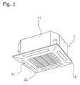
  • Fig. 1 is an outer perspective view of an indoor unit of an air conditioner according to one embodiment of the present invention.
  • Fig. 2 is a bottom view showing the interior of the indoor unit of the air conditioner according to one embodiment of the present invention.
  • Fig. 3 is a cross-sectional view taken along the line A-O-A shown in Fig. 2.
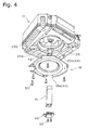
  • Fig. 4 is an exploded perspective view showing the assembly of the bell mouth and electrical component box of the casing.
  • Fig. 5 is an enlarged cross-sectional view of the area around the electrical component box of Fig. 2.
  • Best Mode For Carrying Out The Invention
    An embodiment of the present invention will be described below with reference to the figures.
    (1) Structure of the air conditioner
    An outer perspective view (ceiling omitted) of an indoor unit 1 of an air conditioner according to one embodiment of the present invention is shown in Fig. 1. The indoor unit 1 is built into a ceiling, and includes a casing 11 that is built into the ceiling and a decoration panel 12 disposed on the bottom surface of the casing 11.
    The casing 11 is a member for supporting the components of the indoor unit 1 therein. In the present embodiment, the casing 11 has a substantially rectangular shaped exterior.
    The decoration panel 12 includes an air suction port 20 provided in the middle of the bottom surface, and four rectangular air discharge ports 21 that are provided around the outer circumference of the air suction port 20.
    Next, the interior of the casing 11 will be described with reference to Figs. 2 and 3. Fig. 2 is a bottom view of the interior of the indoor unit 1, and Fig. 3 is a cross-sectional view taken along the line A-O-A of Fig. 2. The casing 11 primarily includes a centrifugal fan 17, a heat exchanger 27, a drain pan 25, a bell mouth 18, and an electrical component box 16. In addition, a line connector 26 is formed in one comer 11a of the casing 11, and is composed of an empty space in which a connecting line between the heat exchanger 27 and an outdoor unit (not shown in the figures) is disposed. Here, the electrical component box 56 depicted with a dashed line in Figs. 2 and 3 illustrates the position of a conventional electrical component box.
    The centrifugal fan 17 is a device for taking air in from the air suction port 20 and discharging air on the sides thereof, and is disposed on the upper side of the air suction port 20 and mounted on the top surface of the casing 11. Here, the rotational axis of the centrifugal fan 17 is represented by the line O-O, and the direction of rotation of the centrifugal fan 17 is represented by R.
    The heat exchanger 27 is a device for exchanging heat with the air discharged from the centrifugal fan 17, and is disposed such that it surrounds the centrifugal fan 17. In the present embodiment, the heat exchanger 27 is a member in which a cross fin type heat exchange panel has been bent, and includes two concave portions 27a, 27c and two convex portions 27b, 27d. Specifically, the concave portion 27a is a member that is formed such that it draws near the outer circumference of the centrifugal fan 17, and in the present embodiment, is formed opposite one of the air discharge ports 21 that is adjacent to the line connector 26. In addition, the convex portion 27b is a member that is formed such that it extends away from the outer circumference of the centrifugal fan 17, and in the present embodiment, is formed opposite one of the comers 11a nearest the line connector 26. Moreover, the concave portion 27c is disposed opposite one of the air discharge ports 21 that is between the convex portions 27b and 27d, and the convex portion 27d is formed opposite the comer 11a that is adjacent to the concave portion 27c.
    The drain pan 25 is a plate like member made of a resin and serves to receive condensed water produced when air in the heat exchanger 27 is cooled. It is disposed on the lower surface of the heat exchanger 27, and is mounted on the lower part of the casing 11. As shown in Fig. 4, the drain pan 25 includes a cylindrical hole 25a that corresponds to the air suction port 20, square holes 25b that correspond to the four air discharge ports 21, and a first slot 25c that is notched in a rectangular shape in the peripheral surface of the cylindrical hole 25a. The first slot 25c is disposed in a position corresponding to one of the comers 11a of the casing 11.
    As shown in Figs. 3 and 4, the bell mouth 18 is a plate member that has a bell shaped opening in the center thereof, is disposed in between the air suction port 20 and the drain pan 25, and is mounted to the drain pan 25 with attachment screws 30. A second slot 18a that is notched in a position corresponding to the first slot 25c of the drain pan 25 is formed in the peripheral surface of the bell mouth 18. Thus, by vertically stacking the first slot 25c with the second slot 18a, a opening 44 is formed, and the lower end of the electric component box 16 is disposed thereon.
    The electric component box 16 is a device for storing electric components used for such things as operational control of the air conditioner, and has a shape that extends from the top surface of the casing 11 to the bell mouth 18. As shown in Fig. 2, in the present embodiment the electric component box 16 is disposed between the outer circumference of the centrifugal fan 17 and the convex portion 27b of the heat exchanger 27. As shown in Figs. 4 and 5, the electrical component box 16 includes an electrical component box main body 41 that stores electrical components used for such things as operational control of the air conditioner, a main body mounting member 42 that allows the electrical component box main body 41 to be freely attached and detached therefrom, and a lid member 43 for opening and closing the electrical component box main body 41.
    The electrical component box main body 41 is a rectangular box shaped member that stores electrical components used for such things as operational control of the air conditioner, and a catch member 41 a is formed on an upper lateral surface thereof.
    The main body mounting member 42 includes an attachment surface 42a that is attached to the top surface of the casing 11 by means of attachment screws 31, a first lateral surface 42b that extends downward from the edge of the attachment surface 42a adjacent to the centrifugal fan 17, a second lateral surface 42c that extends downward from the edge of the attachment surface 42a adjacent to the heat exchanger 27, and a support surface 42d that extends from a lower edge of the second lateral surface 42c toward the centrifugal fan 17. A slit 42e is formed in the first lateral surface 42b, and engages with the catch member 41a on the electrical component box main body 41. A projection 42f that projects toward the electrical component box main body 41 is formed on the second lateral surface 42c, and supports one lateral surface of the electrical component box main body 41. The support surface 42d supports the lower end of the electrical component box main body 41.
    The lid member 43 is a plate shaped member that is disposed such that it is interposed between the periphery of the second slot 18a of the bell mouth 18 and the lower edge of the electrical component box main body 41. The lid member 43 is mounted to the electrical component box main body 41 by means of attachment screws 32.
    The construction of the aforementioned electrical component box 16 allows the electrical component box main body 41 to be freely attached to and detached from the main body mounting member 42. In addition, the periphery of the second slot 18a of the bell mouth 18 is supported such that it is pushed upward by the lid member 43.
    (2) Operation of the air conditioner
    The operation of the indoor unit 1 will be described with reference to Fig. 3.
    As shown by the arrow W in Fig. 3, when the centrifugal fan 17 is rotated, indoor air is drawn into the interior of the indoor unit 1 from the air suction port 20. The air drawn therein, as shown by the arrow X in Fig. 3, is discharged to the outer circumferential portion of the centrifugal fan 17. The air discharged to the outer circumferential portion of the centrifugal fan 17, as shown by the arrow Y, exchanges heat with the heat exchanger 27 disposed on the outer circumferential side of the centrifugal fan 17, and is discharged to the interior of the room from the air discharge ports 21 provided in the bottom portion of the casing 11.
    (3) Attachment and removal of the electrical component box
    The attachment and removal of the electrical component box main body 41 that occurs during inspection of the electronic component box 16 will be described with reference to Fig. 5.
    The process of removing the electrical component box main body 41 from the main body mounting member 42 will be described.
    First, the attachment screws 32 are removed, and the lid member 43 is removed. Next, the lower edge of the electrical component box main body 41 is pulled toward the centrifugal fan 17. When this occurs, the electrical component box main body 41 uses the projection 42f on the main body mounting member 42 as a fulcrum and tilts, and the catch member 41 a on the electrical component box main body 41 is detached from the slit 42e in the main body mounting member 42. After this, the electrical component box main body 41 is pulled downward diagonally from the opening 44.
    When mounting the electrical component box main body on the main body mounting member, the aforementioned removal process is reversed.
    (4) Special characteristics of the air conditioner
    As described above, the special characteristics of the air conditioner of the present embodiment are as follows:
    1 ○ Maintenance of the gap between the bell mouth 18 and the centrifugal fan 17
    As shown in Figs. 2 and 3, because the conventional electrical component box 56 is disposed on the outer circumference of the bell mouth 18, the weight of the electrical component box 56 acts upon the outer circumference of the bell mouth 18, and there is a risk that the vertical position of the bell mouth 18 will change.
    However, because the electrical component box 16 of the present embodiment is mounted to the top surface of the casing 11, it is difficult for the weight of the electrical component box 16 to act upon the bell mouth. Thus, the overlap distance (relative distance) d between the centrifugal fan 17 and the bell mouth 18 can be maintained at a predetermined amount, and the ability of the centrifugal fan 17 to blow air will not be hindered.
    2 ○ Stability of the vertical position of the bell mouth 18
    In the present embodiment, the bell mouth 18 is supported by the electrical component box 16 mounted on the top surface of the casing 11. In other words, the bell mouth 18 is supported by the top surface of the casing 11 via the electrical component box 16. Thus, the vertical position of the bell mouth 18 can be set and stabilized.
    3 ○ Ease of attaching and removing the electrical component box 16
    In the present embodiment, the electrical component box main body 41 can be easily removed during inspection of the electrical components because the electrical component box main body 41 is mounted to the main body mounting member 42 mounted to the top surface of the casing 11 such that it can be freely attached thereto and removed therefrom. In addition, the number of parts can be reduced because the lid member 43 of the electrical component box 16 closes the lower end of the electrical component box 16 and supports the bell mouth 18.
    4 ○ Placement of the electrical component box 16 so that it provides little resistance to the flow of air
    In the present invention, the electrical component box 16 provides little resistance to the air blown out from the centrifugal fan 17 to the outer circumference thereof because it is disposed in a position between the air discharge ports 21 provided in each side of the casing 11.
    5 ○ Increase in the effective length of the heat exchanger 27
    In the present embodiment, the effective length of the heat exchanger 27 is longer than that of a conventional heat exchanger because it has two concave portions 27a, 27c and two convex portions 27b, 27d. Thus, the surface area of the openings of the air discharge ports 21 will not be reduced because the concave portions 27a, 27c are disposed in positions opposite the air discharge ports 21.
    6 ○ Increase in the amount of space in the casing 11
    In the present embodiment, the convex portion 27b in the heat exchanger 27 is disposed in a position opposite the comer 11a of the casing 11. Thus, the size of the area between the outer circumference of the centrifugal fan 17 and the convex portion 27b is larger than the other areas. Thus, the space in the casing 11 can be effectively used because the electrical component box 16 is disposed in this area.
    (5) Other Embodiments
    An embodiment of the present invention was described above based upon the figures. However, the specific construction of the present invention is not limited to this embodiment, and can be modified within a range that does not depart from the essence of the invention.
    For example, in the aforementioned embodiment, the present invention is applied to an air conditioner that is built into a ceiling. However, the present invention can also be applied to an air conditioner that is hung from the ceiling.
    Industrial Applicability
    The relative position between the centrifugal fan and the bell house can be maintained at a predetermined value and the ability of the centrifugal fan to blow air will not be hindered because the present invention is constructed such that is difficult for the weight of the electrical component box to act upon the bell mouth.

    Claims (6)

    1. An air conditioner (1) built into or hung from a ceiling, comprising:
      a casing (11);
      an air suction port (20) provided in the lower surface of the casing (11) for taking in air into the interior thereof;
      a centrifugal fan (17) disposed inside the casing (11) and above the air suction port (20);
      a heat exchanger (27) disposed such that it surrounds the centrifugal fan (17);
      a plurality of air discharge ports (21) provided in the casing (11) and disposed in an outer circumference of the heat exchanger (27) discharge air to an exterior of the casing (11);
      a bell mouth (18) disposed between the air suction port (20) and the centrifugal fan (17); and
      an electrical component box (16) that is mounted on a top surface of the casing (11) and which stores electrical components.
    2. The air conditioner (1) according to claim 1, wherein
         the electrical component box (16) extends from the top surface of the casing (11) to the bell mouth; and
         the bell mouth (18) is supported by the electrical component box (16).
    3. The air conditioner (1) according to claim 2, wherein the electrical component box (16) comprises
         an electrical component box main body (41) that stores electrical components;
         a main body mounting member (42) that is mounted to the top surface of the casing (11) and serves to mount the electrical component box main body (41) such that it may be freely attached thereto and removed therefrom; and
         a lid member (43) disposed between the bell mouth (11) and a lower end of the electrical component box main body (41) that serves to open and close the electrical component box main body (41).
    4. The air conditioner (1) according to any of claims 1 to 3, wherein the electrical component box (16) is disposed in a position between the plurality of air discharge ports (21).
    5. The air conditioner (1) according to claim 4, wherein
         the casing (11) is approximately rectangular in shape;
         the plurality of air discharge ports (21) are disposed in positions opposite each side of the casing (11); and
         the electrical component box (16) is disposed in a position opposite one comer (11a) of the casing (11).
    6. The air conditioner (1) according to claim 5, wherein
         the heat exchanger (27) includes a plurality of convex portions (27b, 27d) that are formed such that they extend away from an outer circumference of the centrifugal fan (17), and a plurality of concave portions (27a, 27c) that are formed such that they draw near to the outer circumference of the centrifugal fan (17);
         the convex portions (27b, 27d) are at least disposed in positions opposite the comers (11a); and
         the electrical component box (16) is disposed in a position between the outer circumference of the centrifugal fan (17) and the convex portions (27b, 27d).
    EP02738810A 2001-09-21 2002-06-26 AIR CONDITIONER Withdrawn EP1471310A4 (en)

    Applications Claiming Priority (3)

    Application Number Priority Date Filing Date Title
    JP2001287998 2001-09-21
    JP2001287998A JP3669315B2 (en) 2001-09-21 2001-09-21 Air conditioner
    PCT/JP2002/006456 WO2003027576A1 (en) 2001-09-21 2002-06-26 Air conditioner

    Publications (2)

    Publication Number Publication Date
    EP1471310A1 true EP1471310A1 (en) 2004-10-27
    EP1471310A4 EP1471310A4 (en) 2009-12-09

    Family

    ID=19110714

    Family Applications (1)

    Application Number Title Priority Date Filing Date
    EP02738810A Withdrawn EP1471310A4 (en) 2001-09-21 2002-06-26 AIR CONDITIONER

    Country Status (5)

    Country Link
    EP (1) EP1471310A4 (en)
    JP (1) JP3669315B2 (en)
    KR (1) KR100513092B1 (en)
    CN (2) CN2536950Y (en)
    WO (1) WO2003027576A1 (en)

    Cited By (5)

    * Cited by examiner, † Cited by third party
    Publication number Priority date Publication date Assignee Title
    EP1548372A4 (en) * 2002-08-30 2008-05-14 Toshiba Carrier Corp APPARATUS FOR AIR CONDITIONING IN CEILING
    NL2001226C2 (en) * 2007-07-18 2010-07-08 Samsung Electronics Co Ltd Plafond airconditioner.
    EP3187794A1 (en) * 2015-12-31 2017-07-05 Lg Electronics Inc. Air conditioner
    EP3060855A4 (en) * 2013-11-12 2017-07-12 Samsung Electronics Co., Ltd. Indoor unit of ceiling type air-conditioner
    EP3598020A4 (en) * 2017-03-15 2020-11-18 Toshiba Carrier Corporation INDOOR UNIT FOR AIR CONDITIONING

    Families Citing this family (5)

    * Cited by examiner, † Cited by third party
    Publication number Priority date Publication date Assignee Title
    KR20050038710A (en) 2003-10-22 2005-04-29 삼성전자주식회사 Blower and air conditioner with the same
    CN102635899A (en) * 2012-05-07 2012-08-15 无锡市汉马空调与通风设备有限公司 Embedded fan coil pipe provided with detachable control device
    CN104896574A (en) * 2014-03-05 2015-09-09 珠海格力电器股份有限公司 Air conditioner indoor unit
    CN105222305B (en) * 2015-10-16 2018-11-13 珠海格力电器股份有限公司 Fan assembly and air conditioner provided with same
    CN113375228B (en) * 2021-06-15 2022-11-22 美的集团(上海)有限公司 Air conditioner

    Family Cites Families (7)

    * Cited by examiner, † Cited by third party
    Publication number Priority date Publication date Assignee Title
    JP2639223B2 (en) 1991-01-10 1997-08-06 三菱電機株式会社 Indoor unit of air conditioner
    JP2998630B2 (en) * 1996-03-06 2000-01-11 ダイキン工業株式会社 Ceiling-mounted air conditioner
    JPH09303815A (en) * 1996-05-09 1997-11-28 Matsushita Refrig Co Ltd Air conditioner
    JP3013829B2 (en) * 1998-01-16 2000-02-28 ダイキン工業株式会社 Air conditioner
    JPH11264575A (en) * 1998-03-19 1999-09-28 Fujitsu General Ltd Ceiling-mounted air conditioner
    JP2000065385A (en) * 1998-08-25 2000-03-03 Fujitsu General Ltd Ceiling-mounted air conditioner
    KR100402195B1 (en) * 2000-01-28 2003-10-22 도시바 캐리어 가부시키 가이샤 Cassette type air conditioner for mounting in the ceiling

    Cited By (7)

    * Cited by examiner, † Cited by third party
    Publication number Priority date Publication date Assignee Title
    EP1548372A4 (en) * 2002-08-30 2008-05-14 Toshiba Carrier Corp APPARATUS FOR AIR CONDITIONING IN CEILING
    NL2001226C2 (en) * 2007-07-18 2010-07-08 Samsung Electronics Co Ltd Plafond airconditioner.
    EP3060855A4 (en) * 2013-11-12 2017-07-12 Samsung Electronics Co., Ltd. Indoor unit of ceiling type air-conditioner
    US9746231B2 (en) 2013-11-12 2017-08-29 Samsung Electronics Co., Ltd. Indoor unit of ceiling type air-conditioner
    EP3187794A1 (en) * 2015-12-31 2017-07-05 Lg Electronics Inc. Air conditioner
    US10544947B2 (en) 2015-12-31 2020-01-28 Lg Electronics Inc. Air conditioner
    EP3598020A4 (en) * 2017-03-15 2020-11-18 Toshiba Carrier Corporation INDOOR UNIT FOR AIR CONDITIONING

    Also Published As

    Publication number Publication date
    KR100513092B1 (en) 2005-09-07
    WO2003027576A1 (en) 2003-04-03
    CN1198095C (en) 2005-04-20
    JP2003097821A (en) 2003-04-03
    CN1410726A (en) 2003-04-16
    CN2536950Y (en) 2003-02-19
    EP1471310A4 (en) 2009-12-09
    JP3669315B2 (en) 2005-07-06
    KR20030046486A (en) 2003-06-12

    Similar Documents

    Publication Publication Date Title
    US6470699B1 (en) Ceiling cassette type air conditioner
    EP1003002B1 (en) Air conditioner
    EP1471310A1 (en) Air conditioner
    US9982908B2 (en) Air conditioner
    JP2001221455A (en) Ceiling cassette type air conditioner
    US20040093886A1 (en) Air conditioner
    JP2016080209A (en) Ceiling-embedded air conditioner
    KR102203437B1 (en) Indoor Unit for Air Conditioner
    JP5401355B2 (en) Air conditioner indoor unit
    WO2007088962A1 (en) Air conditioner
    CN112601915B (en) Air conditioner
    JPH11351660A (en) Air conditioner
    JPH08320132A (en) Wall-mounted air conditioning indoor unit
    JP2024062250A (en) Indoor unit
    JP7196284B2 (en) Air conditioner indoor unit
    KR100605923B1 (en) Indoor unit of heat exchanger and air conditioner
    JPH10196993A (en) Air conditioner
    JP2004144309A (en) Ceiling mounted air conditioner
    JP2000249362A (en) Built-in type air conditioner
    JP2002130721A (en) Air conditioner
    JP2024062251A (en) Indoor unit
    JP4857794B2 (en) Air conditioner indoor unit
    KR20030027235A (en) structure setting a printed circuit board of air-conditioner
    JP2001099481A (en) Ceiling-mounted air conditioner
    JP2015190636A (en) Air conditioner

    Legal Events

    Date Code Title Description
    PUAI Public reference made under article 153(3) epc to a published international application that has entered the european phase

    Free format text: ORIGINAL CODE: 0009012

    17P Request for examination filed

    Effective date: 20030306

    AK Designated contracting states

    Kind code of ref document: A1

    Designated state(s): AT BE CH CY DE DK ES FI FR GB GR IE IT LI LU MC NL PT SE TR

    A4 Supplementary search report drawn up and despatched

    Effective date: 20091111

    RIC1 Information provided on ipc code assigned before grant

    Ipc: F24F 1/00 20060101AFI20030405BHEP

    Ipc: F24F 13/20 20060101ALI20091105BHEP

    17Q First examination report despatched

    Effective date: 20100414

    STAA Information on the status of an ep patent application or granted ep patent

    Free format text: STATUS: THE APPLICATION HAS BEEN WITHDRAWN

    18W Application withdrawn

    Effective date: 20100616