EP1471226A2 - Engine cooling device - Google Patents
Engine cooling device Download PDFInfo
- Publication number
- EP1471226A2 EP1471226A2 EP20040007658 EP04007658A EP1471226A2 EP 1471226 A2 EP1471226 A2 EP 1471226A2 EP 20040007658 EP20040007658 EP 20040007658 EP 04007658 A EP04007658 A EP 04007658A EP 1471226 A2 EP1471226 A2 EP 1471226A2
- Authority
- EP
- European Patent Office
- Prior art keywords
- engine
- passage
- heat
- cooling
- accumulating
- Prior art date
- Legal status (The legal status is an assumption and is not a legal conclusion. Google has not performed a legal analysis and makes no representation as to the accuracy of the status listed.)
- Withdrawn
Links
Images


Classifications
-
- F—MECHANICAL ENGINEERING; LIGHTING; HEATING; WEAPONS; BLASTING
- F02—COMBUSTION ENGINES; HOT-GAS OR COMBUSTION-PRODUCT ENGINE PLANTS
- F02N—STARTING OF COMBUSTION ENGINES; STARTING AIDS FOR SUCH ENGINES, NOT OTHERWISE PROVIDED FOR
- F02N19/00—Starting aids for combustion engines, not otherwise provided for
- F02N19/02—Aiding engine start by thermal means, e.g. using lighted wicks
- F02N19/04—Aiding engine start by thermal means, e.g. using lighted wicks by heating of fluids used in engines
- F02N19/10—Aiding engine start by thermal means, e.g. using lighted wicks by heating of fluids used in engines by heating of engine coolants
-
- F—MECHANICAL ENGINEERING; LIGHTING; HEATING; WEAPONS; BLASTING
- F01—MACHINES OR ENGINES IN GENERAL; ENGINE PLANTS IN GENERAL; STEAM ENGINES
- F01P—COOLING OF MACHINES OR ENGINES IN GENERAL; COOLING OF INTERNAL-COMBUSTION ENGINES
- F01P11/00—Component parts, details, or accessories not provided for in, or of interest apart from, groups F01P1/00 - F01P9/00
- F01P11/14—Indicating devices; Other safety devices
- F01P11/20—Indicating devices; Other safety devices concerning atmospheric freezing conditions, e.g. automatically draining or heating during frosty weather
-
- F—MECHANICAL ENGINEERING; LIGHTING; HEATING; WEAPONS; BLASTING
- F01—MACHINES OR ENGINES IN GENERAL; ENGINE PLANTS IN GENERAL; STEAM ENGINES
- F01P—COOLING OF MACHINES OR ENGINES IN GENERAL; COOLING OF INTERNAL-COMBUSTION ENGINES
- F01P7/00—Controlling of coolant flow
- F01P7/14—Controlling of coolant flow the coolant being liquid
- F01P7/16—Controlling of coolant flow the coolant being liquid by thermostatic control
- F01P7/162—Controlling of coolant flow the coolant being liquid by thermostatic control by cutting in and out of pumps
-
- F—MECHANICAL ENGINEERING; LIGHTING; HEATING; WEAPONS; BLASTING
- F01—MACHINES OR ENGINES IN GENERAL; ENGINE PLANTS IN GENERAL; STEAM ENGINES
- F01P—COOLING OF MACHINES OR ENGINES IN GENERAL; COOLING OF INTERNAL-COMBUSTION ENGINES
- F01P7/00—Controlling of coolant flow
- F01P7/14—Controlling of coolant flow the coolant being liquid
- F01P7/16—Controlling of coolant flow the coolant being liquid by thermostatic control
- F01P7/165—Controlling of coolant flow the coolant being liquid by thermostatic control characterised by systems with two or more loops
-
- F—MECHANICAL ENGINEERING; LIGHTING; HEATING; WEAPONS; BLASTING
- F01—MACHINES OR ENGINES IN GENERAL; ENGINE PLANTS IN GENERAL; STEAM ENGINES
- F01P—COOLING OF MACHINES OR ENGINES IN GENERAL; COOLING OF INTERNAL-COMBUSTION ENGINES
- F01P11/00—Component parts, details, or accessories not provided for in, or of interest apart from, groups F01P1/00 - F01P9/00
- F01P11/14—Indicating devices; Other safety devices
- F01P2011/205—Indicating devices; Other safety devices using heat-accumulators
-
- F—MECHANICAL ENGINEERING; LIGHTING; HEATING; WEAPONS; BLASTING
- F01—MACHINES OR ENGINES IN GENERAL; ENGINE PLANTS IN GENERAL; STEAM ENGINES
- F01P—COOLING OF MACHINES OR ENGINES IN GENERAL; COOLING OF INTERNAL-COMBUSTION ENGINES
- F01P2060/00—Cooling circuits using auxiliaries
- F01P2060/08—Cabin heater
Definitions
- the invention relates to an engine cooling device designed to cool an engine through circulation of cooling medium.
- a cooling device of this type causes cooling medium that has reached a high temperature by receiving heat from an engine to flow into a heat-accumulating container, and thereby makes it possible to thermally insulate and store the cooling medium.
- a radiator passage and a bypass passage are provided as cooling medium passages for causing cooling medium to flow.
- the radiator passage is designed to cause cooling medium that has flown out from a body of an engine to flow into the body of the engine via a radiator.
- the bypass passage is designed to cause cooling medium that has flown out from the body of the engine to flow into the body of the engine without causing the cooling medium to-flow via the radiator.
- the bypass passage is provided with a control valve.
- the flow rate of cooling medium flowing through the bypass passage can be adjusted through control of the control valve.
- a cooling circuit for causing cooling medium to circulate is so constructed as to include the control valve, the radiator passage, and the bypass passage.
- a cooling medium passage there is provided a heat-accumulating passage that has a heat-accumulating container and that can be selectively connected to the cooling circuit.
- This heat-accumulating passage is connected to the cooling circuit, whereby a heat-accumulating circuit for causing cooling medium in the heat-accumulating container to circulate via the body of the engine is constructed.
- the bypass passage is closed to prevent low-temperature cooling medium from being recirculated to the body of the engine.
- the warm-up performance of the engine is further enhanced.
- the flow resistance of cooling medium is increased by closing the bypass passage.
- the cooling medium cannot be guaranteed to flow through the cooling circuit and the heat-accumulating circuit at a sufficient flow rate. This results in a delay in warming up the engine.
- the invention has been made in consideration of the aforementioned circumstances. It is an object of the invention to provide an engine cooling device capable of suitably promoting the warm-up of an engine.
- This cooling device has a cooling circuit and a heat-accumulating passage.
- the cooling circuit is so constructed as to include a radiator passage for causing cooling medium flowing from a body of an engine to flow into the body of the engine via a radiator, a bypass passage for causing cooling medium flowing out from the body of the engine to flow into the body of the engine without flowing via the radiator, and a control valve for controlling a flow rate of cooling medium flowing through the bypass passage.
- the heat-accumulating passage is provided with a heat-accumulating container for storing the cooling medium in a thermally insulated state and that constitutes a heat-accumulating circuit for causing the cooling medium in the heat-accumulating container to circulate via the body of the engine by being selectively connected to the cooling circuit.
- the cooling device comprises control means that i) completes the heat-accumulating circuit by connecting the heat-accumulating passage to the cooling circuit to supply the cooling medium in the heat-accumulating container to the body of the engine and opens the control valve to increase a flow rate of cooling medium flowing through the bypass passage, and then ii) disconnects the heat-accumulating passage from the cooling circuit and that closes the control valve.
- the flow resistance of cooling medium is reduced through an increase in the flow rate of the cooling medium flowing through the bypass passage. Therefore, the flow rate of cooling medium flowing through the cooling circuit and the heat-accumulating circuit is increased. Because the cooling medium in the heat-accumulating container is thereby supplied to the body of the engine at an early stage, the warm-up of the engine can be promoted suitably. After the cooling medium in the heat-accumulating container has been supplied to the body of the engine, the heat-accumulating passage is disconnected from the cooling circuit and the control valve is closed. Therefore, the recirculation of low-temperature cooling medium to the body of the engine is restricted. Thereby, the temperature of the body of the engine can be suitably restrained from falling due to the low-temperature cooling medium.
- control means may i) complete the heat-accumulating circuit by connecting the heat-accumulating passage to the cooling circuit and open the control valve prior to an operation of starting the engine, and may ii) disconnect the heat-accumulating passage from the cooling circuit and close the control valve immediately after the engine has been started.
- control means may determine that the engine has just been started, if cooling medium for cooling the body of the engine is at a temperature lower than a predetermined temperature.
- control means may determine that the engine has just been started, unless a predetermined time has elapsed since completion of the starting of the engine.
- the cooling circuit may be so constructed as to further include a throttle passage for causing cooling medium flowing out from the body of the engine to flow into the body of the engine via a throttle body, and a throttle open-close valve for opening and closing the throttle passage.
- the control means may open the throttle open-close valve in supplying cooling medium in the heat-accumulating container to the body of the engine through the heat-accumulating circuit by connecting the heat-accumulating passage to the cooling circuit, and may close the throttle open-close valve in disconnecting the heat-accumulating passage from the cooling circuit.
- the flow resistance of cooling medium is reduced through an increase in the flow rate of the cooling medium flowing through the throttle passage. Therefore, the flow rate of cooling medium flowing through the cooling circuit and the heat-accumulating circuit is increased.
- the cooling medium in the heat-accumulating container is thereby supplied to the body of the engine at an earlier stage. As a result, the warm-up performance of the engine can further be enhanced.
- the throttle open-close valve is closed, whereby the recirculation of low-temperature cooling medium to the body of the engine through the throttle passage is restricted. Thereby, the temperature of the body of the engine can be suitably restrained from falling due to the inflow of low-temperature cooling medium into the body of the engine.
- the cooling circuit may be so constructed as to further include a heater passage for causing cooling medium flowing out from the body of the engine to flow into the body of the engine via a heater core, and a heater open-close valve for opening and closing the heater passage.
- the control means may open the heater open-close valve in supplying cooling medium in the heat-accumulating container to the body of the engine through the heat-accumulating circuit by connecting the heat-accumulating passage to the cooling circuit, and may close the heater open-close valve in disconnecting the heat-accumulating passage from the cooling circuit.
- the flow resistance of cooling medium is reduced through an increase in the flow rate of the cooling medium flowing through the heater passage. Therefore, the flow rate of cooling medium flowing through the cooling circuit and the heat-accumulating circuit is increased.
- the cooling medium in the heat-accumulating container is thereby supplied to the body of the engine at an earlier stage. As a result, the warm-up performance of the engine can further be enhanced.
- the heater open-close valve is closed, whereby the recirculation of low-temperature cooling medium to the body of the engine through the heater passage is restricted. Thereby, the temperature of the body of the engine can be suitably restrained from falling due to the inflow of low-temperature cooling medium into the body of the engine.
- the control means may prohibit the heat-accumulating passage from being connected to the cooling circuit if cooling medium in the heat-accumulating container is at a temperature lower than a predetermined temperature. According to the construction as described herein, since low-temperature cooling medium in the heat-accumulating container is not supplied to the body of the engine during start thereof, a deterioration in the warm-up performance of the engine can be avoided suitably.
- the predetermined temperature may be a temperature of coolant for cooling the body of the engine.
- the control means prohibits the heat-accumulating passage from being connected to the cooling circuit if cooling medium for cooling the body of the engine is at a temperature lower than a predetermined temperature.
- the predetermined temperature may be a cold-state criterion temperature or an outside air temperature.
- control means may close the radiator passage both in opening the control valve and in closing the control valve.
- FIG. 1 The overall construction of an engine cooling device having a function of cooling an engine E (engine body) is illustrated in Fig. 1.
- a water pump 11 is driven through the engine E and force-feeds coolant.
- a radiator 12 exchanges heat between coolant and outside air.
- a throttle body 13 contains a throttle valve and adjusts the amount of intake air in accordance with the opening of the valve.
- a heater core 14 exchanges heat between coolant and air for heating the interior of a vehicle compartment.
- the heat-exchanged air is supplied to the interior of the vehicle compartment through a heater.
- An electric water pump 15 is driven through a battery and force-feeds coolant.
- a heat-accumulating container 16 stores coolant and thermally insulates the coolant from air outside the container. Thus, the coolant is stored in the heat-accumulating container 16 while being held constant in temperature.
- a coolant delivery pipe 17 causes coolant that has flown out from the heat-accumulating container 16 to flow into a cylinder head of the engine E.
- a thermostat 21 operates in accordance with the temperature of coolant, and adjusts the flow rate of coolant flowing into a radiator 12.
- the thermostat 21 assumes a minimum opening (i.e., when the thermostat 21 is closed)
- the flow rate of coolant flowing into the radiator 12 is "0".
- the opening of the thermostat 21 approaches a maximum opening, the flow rate of coolant flowing into the radiator 12 increases.
- a flow rate control valve 22 is continuously variable in opening and adjusts the flow rate of coolant flowing through a flow passage (bypass passage) for causing the coolant to circulate while bypassing the radiator 12.
- a flow passage bypass passage
- the flow rate of coolant flowing through the flow passage is "0".
- the opening of the flow rate control valve 22 approaches a maximum opening, the flow rate of coolant flowing through the flow passage increases.
- An open-close valve 23 can be switched to its open or closed state, and changes over the flow pattern of coolant in a flow passage (throttle passage) for causing the coolant to flow into a throttle body 13.
- a flow passage throttle passage
- a three-way valve 24 has three ports (i.e., a first port P1, a second port P2, and a third port P3), and selectively changes over the circulation pattern of coolant by changing open-close states among the ports.
- An electronic control unit (ECU) 3 comprehensively controls an injector INJ of the engine E, the electric water pump 15, the flow rate control valve 22, the open-close valve 23, and the three-way valve 24.
- the construction of the controller (control means) includes the ECU 3.
- An engine coolant temperature sensor S detects a temperature (engine coolant temperature THwe) of coolant for cooling the engine E.
- a system switch S2 detects a request to start the engine E.
- a request to start the engine E can be detected, for example, on the basis of a condition that the changeover position of an ignition switch be shifted to "ON" or a condition that a door be opened through a door open-close switch of the vehicle.
- the ECU 3 monitors the amount of fuel injected from the injector INJ.
- a first cooling passage R1 connects the engine E to the first port P1 of the three-way valve 24.
- a second cooling passage R2 connects the engine E to the thermostat 21.
- a third cooling passage R3 connects the first cooling passage R1 to the radiator 12.
- a fourth cooling passage R4 connects the radiator 12 to the thermostat 21.
- a fifth cooling passage R5 connects the first cooling passage R1 to the flow rate control valve 22.
- a sixth cooling passage R6 connects the flow rate control valve 22 to the second cooling passage R2 via the thermostat 21.
- the sixth cooling passage R6 is in communication with the second cooling passage R2 whether the thermostat 21 is open or closed.
- a seventh cooling passage R7 connects the first cooling passage R1 to the open-close valve 23.
- An eighth cooling passage R8 connects the open-close valve 23 to the throttle body 13.
- a ninth cooling passage R9 connects the throttle body 13 to the second cooling passage R2 via the thermostat 21.
- the ninth cooling passage R9 is in communication with the second cooling passage R2 whether the thermostat 21 is open or closed.
- a tenth cooling passage R10 connects the second port R2 of the three-way valve 24 to the heater core 14.
- An eleventh cooling passage R11 connects the heater core 14 to the second cooling passage R2 via the thermostat 21.
- the eleventh cooling passage R11 is in communication with the second cooling passage R2 whether the thermostat 21 is open or closed.
- a twelfth cooling passage R12 connects the third port P3 of the three-way valve 24 to the electric water pump 15.
- a thirteenth cooling passage R13 connects the electric water pump 15 to the heat-accumulating container 16.
- a fourteenth cooling passage R14 connects the heat-accumulating container 16 to the coolant delivery pipe 17.
- the following cooling passages are constituted through the aforementioned cooling passages respectively.
- the third cooling passage R3 and the fourth cooling passage R4 constitute a radiator passage.
- the radiator passage is open.
- the radiator passage is closed.
- coolant flows via the radiator 12.
- the fifth cooling passage R5 and the sixth cooling passage R6 constitute a bypass passage.
- the bypass passage is open.
- the bypass passage is closed.
- coolant flows while bypassing the radiator 12.
- the seventh cooling passage R7, the eighth cooling passage R8, and the ninth cooling passage R9 constitute a throttle passage.
- the throttle passage is open.
- the throttle passage is closed.
- coolant flows via the throttle body 13.
- the tenth cooling passage R10 and the eleventh passage R11 constitute a heater passage.
- the heater passage can be selectively connected to the first cooling passage R1 through control of the three-way valve 24.
- the heater passage is connected to the first cooling passage R1 (the heater passage is opened).
- the heater passage is disconnected from the first cooling passage R1 (the heater passage is closed).
- coolant flows via the heater core 14.
- the twelfth cooling passage R12, the thirteenth cooling passage R13, and the fourteenth cooling passage R14 constitute a heat-accumulating passage.
- the heat-accumulating passage can be selectively connected to the first cooling passage R1 through control of the three-way valve 24.
- the heat-accumulating passage is connected to the first cooling passage R1 (the heat-accumulating passage is opened).
- the first or third port P1 or P3 of the three-way valve 24 is closed, the heat-accumulating passage is disconnected from the first cooling passage R1 (the heat-accumulating passage is closed).
- coolant flows via the heat-accumulating container 16.
- the following circulation circuits for causing coolant to circulate are constituted by the aforementioned respective cooling passages.
- the first cooling passage R1, the second cooling passage R2, the radiator passage (the third cooling passage R3 and the fourth cooling passage R4), the bypass passage (the fifth cooling passage R5 and the sixth cooling passage R6), the throttle passage (the seventh cooling passage R7, the eighth cooling passage R8, and the ninth cooling passage R9), and the heater passage (the tenth cooling passage R10 and the eleventh cooling passage R11) constitute a cooling circuit.
- the first cooling passage R1 and the heat-accumulating passage (the twelfth cooling passage R12, the thirteenth cooling passage R13, and the fourteenth cooling passage R14) constitute a heat-accumulating circuit.
- the heat-accumulating passage is connected to the cooling circuit (the first cooling passage R1) through control of the three-way valve 24, whereby the heat-accumulating circuit is constituted.
- the heat-accumulating passage is opened to supply the engine E with coolant in the heat-accumulating container 16, whereby the warm-up of the engine E can be promoted.
- a cooling device control process during start of the engine for controlling the driving pattern of the engine cooling device during start of the engine will be described with reference to Figs. 2 and 3.
- This process is composed of "a preheat process” shown in Fig. 2 and "a coolant circulation stoppage process” shown in Fig. 3. It is to be noted herein that the present process corresponds to the process performed through the control means of the invention.
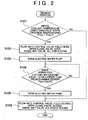
- the preheat process will be described. This process is started upon detection of a request to start the engine E through the system switch S2, and is terminated after the performance of processings in steps S101 to S106 which will be described below.
- step S101 It is determined whether or not an engine coolant temperature THwe is lower than a cold-state criterion temperature THwL (step S101). That is, it is determined whether or not a condition THwe ⁇ THwL is satisfied.
- the cold-state criterion temperature THwL is used as a coolant temperature threshold indicating whether or not the engine E is in a cold state. That is, if the engine coolant temperature THwe is lower than the cold-state criterion temperature THwL, the engine E is in a cold state.
- step S102 If the engine coolant temperature THwe is lower than the cold-state criterion temperature THwL, the following operations are performed (step S102).
- the bypass passage is opened by fully opening the flow rate control valve 22 (i.e., by setting the opening thereof as a maximum opening)
- the throttle passage is opened by opening the open-close valve 23
- the heater passage is connected to the first cooling passage R1 by opening the first and second ports P1 and P2 of the three-way valve 24
- the heat-accumulating passage is connected to the first cooling passage R1 by opening the first and third ports P1 and P3 of the three-way valve 24.
- Coolant is caused to circulate through the bypass passage, the throttle passage, the heater passage, and the heat-accumulating passage by driving the electric water pump 15 (step S103).
- the promotion of warm-up of the engine E through hot coolant (hot fluid) stored in the heat-accumulating container 16, namely, so-called preheat is thereby realized.
- a drive period Tpm for the electric warm pump 15 is equal to or longer than a predetermined period TpmX (step S104). That is, it is determined whether or not a condition Tpm ⁇ TpmX is satisfied. If the condition is not satisfied, the processing in the aforementioned step S104 is repeatedly performed.
- the predetermined drive period TpmX indicates a period that elapses before the hot coolant stored in the heat-accumulating container 16 is sufficiently supplied to the interior of the engine E, and can be set in accordance with the volume of the heat-accumulating container 16 or the size of the engine E.
- step S105 If the drive period Tpm for the electric water pump 15 has become equal to or longer than the predetermined period TpmX (i.e., if preheat has been completed), the electric water pump 15 is stopped (step S105). The circulation of coolant in the engine cooling device 1 is thereby stopped.
- step S106 the following operations are performed.
- the bypass passage is closed by fully closing the flow rate control valve 22 (i.e., by setting the opening thereof as a minimum opening)
- the throttle passage is closed by closing the open-close valve 23
- the heater passage is disconnected from the first cooling passage R1 by closing the first and second ports P1 and P2 of the three-way valve 24
- the heat-accumulating passage is disconnected from the first cooling passage R1 by closing the first and third ports P1 and P3 of the three-way valve 24.
- the respective cooling passages of the engine cooling device 1 are closed to stop the circulation of coolant.
- a cumulative value of fuel injection amounts from the start of the engine E up to now (a fuel injection amount cumulative value FiA) is equal to or larger than a predetermined cumulative value FiX (step S201). That is, it is determined whether or not a condition FiA ⁇ FiX is satisfied.
- the predetermined cumulative value FiX is used as a fuel injection amount threshold cumulative value indicating whether or not the engine E has just been started. Namely, if the injection amount cumulative value is smaller than the predetermined cumulative value FiX, the engine E has just been started.
- the processing in the aforementioned step S201 of determination is repeatedly performed at intervals of a predetermined period.
- the flow rate control valve 22, the open-close valve 23, and the three-way valve 24 are controlled according to the following pattern. Namely, (a) the flow rate control valve 22 is held fully closed, (b) the open-close valve 23 is held closed, (c) the first and second ports P1 and P2 of the three-way valve 24 are held closed, and (d) the first and third ports P1 and P3 of the three-way valve 24 are held closed.
- the engine cooling device 1 is restored to normal control (step S202). That is, the flow rate control valve 22, the open-close valve 23, and the three-way valve 24 are controlled in accordance with the operational state of the engine E or the like.
- the flow rate control valve 22, the open-close valve 23, and the three-way valve 24 are held closed, whereby the circulation of coolant in the engine cooling device 1 is stopped.
- the engine cooling device 1 is controlled through a preheat mode that will be described later.
- the engine cooling device 1 is controlled through a coolant circulation stoppage mode that will be described later.
- the thermostat 21 is basically held closed.
- FIG. 5 shows a pattern according to which coolant circulates when the engine cooling device 1 is controlled through the preheat mode.
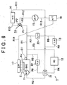
- Fig. 6 shows a pattern according to which coolant circulates when the engine cooling device 1 is controlled through the coolant circulation stoppage mode.
- cooling passages indicated by solid lines represent those through which coolant flows
- arrows represent directions in which coolant flows
- cooling passages indicated by broken lines represent those through which coolant does not flow.
- the electric water pump 15 causes coolant to circulate while the bypass passage, the throttle passage, and the heater passage as well as the heat-accumulating passage are open. Therefore, the coolant flows through all the cooling passages but the radiator passage.
- the flow rate of the hot fluid supplied to the engine E from the heat-accumulating container 16 thereby increases, and the hot fluid in the heat-accumulating container 16 flows into the engine E at an early stage. Therefore, the warm-up of the engine E is promoted suitably.
- the radiator passage, the bypass passage, the throttle passage, the heater passage, and the heat-accumulating passage are closed. Therefore, coolant does not circulate through any of the cooling passages.
- Fig. 7 one example of the control pattern of the engine cooling device 1 according to "the cooling device control process during start of the engine” will be described. It is assumed that a request to start the engine E is detected through a vehicle-door opening operation based on a door open-close switch at a time t71 (see Fig. 7B).
- Coolant is thereby caused to circulate with its flow resistance having been reduced.
- the hot fluid in the heat-accumulating container 16 is supplied to the engine E at an early stage.
- the flow rate control valve 22, the open-close valve 23, and the three-way valve 24 are thereafter controlled in accordance with the operational state of the engine E (Figs. 7C to 7E).
- the bypass passage, the throttle passage, the heater passage, and the heat-accumulating passage are closed.
- the circulation of low-temperature coolant is thereby stopped. Therefore, the engine E can be suitably restrained from being lowered in temperature by low-temperature coolant.
- the warm-up operation of the engine E is performed with the bypass passage, the throttle passage, the heater passage, and the throttle passage being closed. The circulation of coolant is thereby stopped. Therefore, the warm-up of the engine E can be promoted suitably.
- the following determination process can also be added to the preheat process (Fig. 2). That is, it is determined immediately before or after step S101 "whether or not the temperature of coolant in the heat-accumulating container 16 (i.e., a heat-accumulating container coolant temperature THwt) is equal to or higher than a predetermined criterion temperature". In this case, (a) if the heat-accumulating container coolant temperature THwt is equal to or higher than the predetermined criterion temperature, the processings starting from step S102 are sequentially performed.
- step S106 if the heat-accumulating container coolant temperature THwt is lower than the predetermined criterion temperature, the processing in step S106 is performed while omitting the processings in steps S102 to S105.
- the construction as described herein makes it possible to appropriately promote the warm-up of the engine E.
- the following determination processing can also be added to the preheat process (Fig. 2). That is, it is determined immediately before 'or after step S101 "whether or not the temperature of coolant in the heat-accumulating container 16 (i.e., the heat-accumulating container coolant temperature THwt) is equal to or higher than the engine coolant temperature THwe". In this case, (a) if the heat-accumulating container coolant temperature THwt is equal to or higher than the engine coolant temperature THwe, the processings starting from step S 102 are sequentially performed.
- step S106 is performed while omitting the processings in steps S102 to S105.
- the construction as described herein prevents the low-temperature coolant stored in the heat-accumulating container 16 from being supplied to the engine E. As a result, the warm-up performance of the engine E can be suitably restrained from deteriorating.
- step S101 it is determined whether or not the engine coolant temperature THwe is lower than the cold-state criterion temperature THwL, and the processings in steps S102 to S105 (preheat) are performed when this condition is satisfied.
- the invention is not limited to this construction. Namely, it is also appropriate to omit the determination processing in step S101 and to perform the processings starting from step S102 every time the engine E is started.
- the construction as described herein eliminates the necessity to monitor the engine coolant temperature THwe prior to the implementation of preheat. In consequence, the preheat process is simplified.
- preheat is carried out on the ground that the engine coolant temperature THwe is lower than the cold-state criterion temperature THwL.
- the invention is not limited to this construction. Namely, preheat may also be carried out on the ground that the engine coolant temperature THwe is lower than an outside air temperature.
- the cold-state criterion temperature THwL is used in the determination processing of step S101.
- the cold-state criterion temperature THwL can be suitably changed to any temperature "that is equal to or higher than an outside air temperature and that is lower than a coolant temperature indicating the completion of warm-up of the engine E".
- the invention is not limited to this construction. Namely, it may also be determined that the engine E has just been started on the ground that the engine coolant temperature THwe is lower than the predetermined temperature.
- the invention is not limited to this construction. Namely, it may also be determined that the engine E has just been started, on the ground that the elapsed time after completion of the start of the engine E is shorter than a predetermined elapsed time.
- a request to start the engine E can be detected on the basis of the condition that "the changeover position of the ignition switch be shifted to "ON”" or the condition that "the door be opened through the door open-close switch of the vehicle".
- the detection of a request to start the engine can be determined on the basis of other suitable conditions as well as the conditions exemplified in the aforementioned embodiment.
- a request to start the engine may also be detected on the basis of a condition "that the changeover position of the ignition switch be shifted to "START"".
- the open-close valve 23 is opened to open the throttle passage if preheat has not been completed in starting the engine E in a cold state.
- the invention is not limited to this construction. Namely, the open-close valve 23 is closed even if preheat has not been completed in starting the engine E in a cold state. It is also appropriate that the throttle valve be thereby closed.
- the flow rate control valve 22 is fully opened to open the bypass passage.
- the invention is not limited to this construction. Namely, if preheat has not been completed in starting the engine E in a cold state, the flow rate control valve 22 may also be set at any opening between its maximum opening and its minimum opening to open the bypass passage. In short, the control pattern of the flow rate control valve can be suitably changed as long as the flow rate of coolant flowing through the bypass passage is increased when the coolant is caused to circulate through the heat-accumulating circuit in starting the engine E in a cold state.
- the first and second ports P1 and P2 of the three-way valve 24 are opened to open the heater passage.
- the heater passage may also be closed by closing the second port P2 of the three-way valve 24 if preheat has not been completed in starting the engine E in a cold state.
- the thermostat 21 that operates in accordance with the temperature of coolant is used.
- the invention is not limited to this construction. It is also possible to employ an electronic thermostat capable of electrically controlling the release state of a valve. In the construction as described herein, the electronic thermostat is opened to open the radiator passage if preheat has not been completed in starting the engine E in a cold state, whereby the flow resistance of coolant can further be reduced. If any one of the above-mentioned conditions (2) to (4) is satisfied, the recirculation of low-temperature coolant to the engine E can be avoided by closing the electronic thermostat.
- the throttle passage is provided with the open-close valve 23.
- the invention is not limited to this construction. Namely, a flow rate control valve whose opening is continuously variable can also be provided in place of the open-close valve 23.
- bypass passage is provided with the flow rate control valve 22.
- the invention is not limited to this construction. Namely, an open-close valve that can be switched to either its open state or its closed state can also be provided in place of the flow rate control valve 22.
- the preheat process is started in response to a request to start the engine E.
- the invention is not limited to this construction. Namely, the preheat process may also be started in response to the start of the engine E.
- the construction as described herein makes it possible to start the coolant circulation stoppage process after the preheat process has been completed.
- the preheat process is started in response to a request to start the engine E.
- the invention is not limited to this construction.
- the preheat process may also be started immediately after the engine E has been started.
- the construction as described herein makes it possible to start the coolant circulation stoppage process after the preheat process has been completed.
- the heat-accumulating passage is connected to or disconnected from the cooling circuit through control of the three-way valve 24.
- the invention is not limited to this construction. Namely, it is also appropriate that the heat-accumulating passage be provided with an open-close valve, a flow rate control valve or the like and be connected to or disconnected from the cooling circuit through control of the open-close valve, the flow rate control valve or the like.
- the invention is embodied on the assumption that the engine cooling device 1 exemplified in Fig. 1 is to be used.
- the construction of the engine cooling device is not limited to the construction exemplified in the embodiment but can be any suitable construction.
- the cooling device is provided with a cooling circuit composed of a radiator passage, a bypass passage, and a flow rate control valve for controlling the flow rate of coolant flowing through the bypass passage, and with a heat-accumulating passage that includes a heat-accumulating container and that constitutes a heat-accumulating circuit by being selectively connected to the cooling circuit, it is possible to provide the cooling device with any construction.
- the engine cooling device 1 is controlled during start of the engine E through the cooling device control process performed in starting the engine.
- the cooling device control process performed in starting the engine is not limited to the construction exemplified in the embodiment.
- the control pattern can be suitably modified as long as it is constructed such that a heat-accumulating circuit is completed by connecting a heat-accumulating passage to a cooling circuit in starting an engine, that a bypass passage is opened through control of a control valve, that the heat-accumulating passage is disconnected from the cooling circuit after coolant in a heat-accumulating container has been supplied to the engine, and that the bypass passage is closed through control of the control valve.
- the invention provides an engine cooling device capable of suitably promoting the warm-up of an engine.
- This device comprises a cooling circuit and a heat-accumulating passage.
- the cooling circuit is composed of a radiator passage, a bypass passage, and a flow rate control valve 22 for controlling the flow rate of coolant flowing through the bypass passage.
- the heat-accumulating passage is provided with a heat-accumulating container 16, and constitutes a heat-accumulating circuit for causing coolant in the heat-accumulating container 16 to circulate via an engine E.
- the cooling device completes the heat-accumulating circuit by connecting the heat-accumulating passage to the cooling circuit to supply the cooling medium in the heat-accumulating container 16 to the body of the engine E, opens the flow rate control valve 22 to increase a flow rate of cooling medium flowing through the bypass passage, then disconnects the heat-accumulating passage from the cooling circuit, and closes the flow rate control valve 22.
Landscapes
- Engineering & Computer Science (AREA)
- Chemical & Material Sciences (AREA)
- Combustion & Propulsion (AREA)
- Mechanical Engineering (AREA)
- General Engineering & Computer Science (AREA)
- Life Sciences & Earth Sciences (AREA)
- Atmospheric Sciences (AREA)
- Combined Controls Of Internal Combustion Engines (AREA)
- Electrical Control Of Air Or Fuel Supplied To Internal-Combustion Engine (AREA)
- Air-Conditioning For Vehicles (AREA)
Abstract
Description
- The invention relates to an engine cooling device designed to cool an engine through circulation of cooling medium.
- As an engine cooling device designed to cool an engine through circulation of cooling medium, a cooling device equipped with a heat-accumulating container has been known. A cooling device of this type causes cooling medium that has reached a high temperature by receiving heat from an engine to flow into a heat-accumulating container, and thereby makes it possible to thermally insulate and store the cooling medium.
- As an engine cooling device equipped with a heat-accumulating container, there is known a device that is disclosed in Japanese Patent Application No. 10-77839 as an example of the related art. This cooling device is constructed as follows.
- That is, a radiator passage and a bypass passage are provided as cooling medium passages for causing cooling medium to flow. The radiator passage is designed to cause cooling medium that has flown out from a body of an engine to flow into the body of the engine via a radiator. The bypass passage is designed to cause cooling medium that has flown out from the body of the engine to flow into the body of the engine without causing the cooling medium to-flow via the radiator.
- The bypass passage is provided with a control valve. The flow rate of cooling medium flowing through the bypass passage can be adjusted through control of the control valve. A cooling circuit for causing cooling medium to circulate is so constructed as to include the control valve, the radiator passage, and the bypass passage.
- Further, as a cooling medium passage, there is provided a heat-accumulating passage that has a heat-accumulating container and that can be selectively connected to the cooling circuit. This heat-accumulating passage is connected to the cooling circuit, whereby a heat-accumulating circuit for causing cooling medium in the heat-accumulating container to circulate via the body of the engine is constructed.
- In the aforementioned engine cooling device, when the engine is started, hot cooling medium in the heat-accumulating container is caused to flow into the engine by connecting the heat-accumulating passage to the cooling circuit. If the temperature of the cooling medium in the heat-accumulating container becomes lower than a predetermined temperature, the warm-up of the engine is promoted by disconnecting the heat-accumulating passage from the cooling circuit.
- Whether cooling medium in the heat-accumulating container is supplied to the engine or the heat-accumulating passage is disconnected from the cooling circuit, the bypass passage is closed to prevent low-temperature cooling medium from being recirculated to the body of the engine. Thus, the warm-up performance of the engine is further enhanced.
- In causing cooling medium in the heat-accumulating container to flow into the body of the engine, if cooling medium is caused to circulate with the bypass passage closed as in the case of the aforementioned related art, the following problem may arise.
- That is, the flow resistance of cooling medium is increased by closing the bypass passage. Hence, the cooling medium cannot be guaranteed to flow through the cooling circuit and the heat-accumulating circuit at a sufficient flow rate. This results in a delay in warming up the engine.
- The invention has been made in consideration of the aforementioned circumstances. It is an object of the invention to provide an engine cooling device capable of suitably promoting the warm-up of an engine.
- An engine cooling device in accordance with the invention is provided to achieve the above-stated object. This cooling device has a cooling circuit and a heat-accumulating passage. The cooling circuit is so constructed as to include a radiator passage for causing cooling medium flowing from a body of an engine to flow into the body of the engine via a radiator, a bypass passage for causing cooling medium flowing out from the body of the engine to flow into the body of the engine without flowing via the radiator, and a control valve for controlling a flow rate of cooling medium flowing through the bypass passage. The heat-accumulating passage is provided with a heat-accumulating container for storing the cooling medium in a thermally insulated state and that constitutes a heat-accumulating circuit for causing the cooling medium in the heat-accumulating container to circulate via the body of the engine by being selectively connected to the cooling circuit. The cooling device comprises control means that i) completes the heat-accumulating circuit by connecting the heat-accumulating passage to the cooling circuit to supply the cooling medium in the heat-accumulating container to the body of the engine and opens the control valve to increase a flow rate of cooling medium flowing through the bypass passage, and then ii) disconnects the heat-accumulating passage from the cooling circuit and that closes the control valve.
- According to the aforementioned cooling device, when cooling medium in the heat-accumulating container is supplied to the body of the engine, the flow resistance of cooling medium is reduced through an increase in the flow rate of the cooling medium flowing through the bypass passage. Therefore, the flow rate of cooling medium flowing through the cooling circuit and the heat-accumulating circuit is increased. Because the cooling medium in the heat-accumulating container is thereby supplied to the body of the engine at an early stage, the warm-up of the engine can be promoted suitably. After the cooling medium in the heat-accumulating container has been supplied to the body of the engine, the heat-accumulating passage is disconnected from the cooling circuit and the control valve is closed. Therefore, the recirculation of low-temperature cooling medium to the body of the engine is restricted. Thereby, the temperature of the body of the engine can be suitably restrained from falling due to the low-temperature cooling medium.
- In the aforementioned cooling device, the control means may i) complete the heat-accumulating circuit by connecting the heat-accumulating passage to the cooling circuit and open the control valve prior to an operation of starting the engine, and may ii) disconnect the heat-accumulating passage from the cooling circuit and close the control valve immediately after the engine has been started. According to the construction as described herein, since the cooling medium in the heat-accumulating container is supplied to the body of the engine prior to the operation of starting the engine, the engine can be warmed up at an earlier stage.
- In this case, the control means may determine that the engine has just been started, if cooling medium for cooling the body of the engine is at a temperature lower than a predetermined temperature. Alternatively, the control means may determine that the engine has just been started, unless a predetermined time has elapsed since completion of the starting of the engine.
- In the aforementioned cooling device, the cooling circuit may be so constructed as to further include a throttle passage for causing cooling medium flowing out from the body of the engine to flow into the body of the engine via a throttle body, and a throttle open-close valve for opening and closing the throttle passage. The control means may open the throttle open-close valve in supplying cooling medium in the heat-accumulating container to the body of the engine through the heat-accumulating circuit by connecting the heat-accumulating passage to the cooling circuit, and may close the throttle open-close valve in disconnecting the heat-accumulating passage from the cooling circuit.
- According to the construction as described herein, when the cooling medium in the heat-accumulating container is supplied to the body of the engine, the flow resistance of cooling medium is reduced through an increase in the flow rate of the cooling medium flowing through the throttle passage. Therefore, the flow rate of cooling medium flowing through the cooling circuit and the heat-accumulating circuit is increased. The cooling medium in the heat-accumulating container is thereby supplied to the body of the engine at an earlier stage. As a result, the warm-up performance of the engine can further be enhanced. After the cooling medium in the heat-accumulating container has been supplied to the body of the engine, the throttle open-close valve is closed, whereby the recirculation of low-temperature cooling medium to the body of the engine through the throttle passage is restricted. Thereby, the temperature of the body of the engine can be suitably restrained from falling due to the inflow of low-temperature cooling medium into the body of the engine.
- In the aforementioned cooling device, the cooling circuit may be so constructed as to further include a heater passage for causing cooling medium flowing out from the body of the engine to flow into the body of the engine via a heater core, and a heater open-close valve for opening and closing the heater passage. The control means may open the heater open-close valve in supplying cooling medium in the heat-accumulating container to the body of the engine through the heat-accumulating circuit by connecting the heat-accumulating passage to the cooling circuit, and may close the heater open-close valve in disconnecting the heat-accumulating passage from the cooling circuit.
- According to the construction described herein, when the cooling medium in the heat-accumulating container is supplied to the body of the engine, the flow resistance of cooling medium is reduced through an increase in the flow rate of the cooling medium flowing through the heater passage. Therefore, the flow rate of cooling medium flowing through the cooling circuit and the heat-accumulating circuit is increased. The cooling medium in the heat-accumulating container is thereby supplied to the body of the engine at an earlier stage. As a result, the warm-up performance of the engine can further be enhanced. After the cooling medium in the heat-accumulating container has been supplied to the body of the engine, the heater open-close valve is closed, whereby the recirculation of low-temperature cooling medium to the body of the engine through the heater passage is restricted. Thereby, the temperature of the body of the engine can be suitably restrained from falling due to the inflow of low-temperature cooling medium into the body of the engine.
- In the aforementioned cooling device, the control means may prohibit the heat-accumulating passage from being connected to the cooling circuit if cooling medium in the heat-accumulating container is at a temperature lower than a predetermined temperature. According to the construction as described herein, since low-temperature cooling medium in the heat-accumulating container is not supplied to the body of the engine during start thereof, a deterioration in the warm-up performance of the engine can be avoided suitably.
- In this case, the predetermined temperature may be a temperature of coolant for cooling the body of the engine.
- Furthermore, in the aforementioned cooling device, the control means prohibits the heat-accumulating passage from being connected to the cooling circuit if cooling medium for cooling the body of the engine is at a temperature lower than a predetermined temperature. In this case, the predetermined temperature may be a cold-state criterion temperature or an outside air temperature.
- Furthermore, in the aforementioned cooling device, the control means may close the radiator passage both in opening the control valve and in closing the control valve.
- The above-mentioned objects, features, advantages, technical and industrial significance of this invention will be better understood by reading the following detailed description of the exemplary embodiments of the invention, when considered in connection with the accompanying drawings, in which:
- Fig. 1 is a schematic block diagram showing the overall construction of an engine cooling device as a concrete embodiment of the invention;
- Fig. 2 is a flowchart showing a preheat process performed in the embodiment;
- Fig. 3 is a flowchart showing a coolant circulation stoppage process performed in the embodiment;
- Fig. 4 shows control patterns of the engine cooling device according to a cooling device cooling process when starting an engine in the embodiment;
- Fig. 5 is a block diagram of a circulation pattern of coolant during a preheat mode in the engine cooling device of the embodiment;
- Fig. 6 is a block diagram of a circulation pattern of coolant during a coolant circulation stoppage mode in the engine cooling device of the embodiment;
- Fig.7A is a timing chart showing a control pattern that is realized as to operation/stoppage of the engine by a cooling device control process during start of the engine;
- Fig. 7B is a timing chart showing a control pattern that is realized as to the presence of an engine start request by the cooling device control process during the start of the engine;
- Fig. 7C is a timing chart showing a control pattern that is realized as to the opening of a flow rate control valve by the cooling device control process during the start of the engine;
- Fig.7D is a timing chart showing a control pattern that is realized as to the opening/closing of an open-close valve by the cooling device control process during the start of the engine;
- Fig.7E is a timing chart showing a control pattern that is realized as to the opening/closing of all ports of a three-way valve by the cooling device control process during the start of the engine; and
- Fig.7F is a timing chart showing a control pattern that is realized as to the drive/stoppage of an electric water pump by the cooling device control process during the start of the engine.
-
- In the following description, the invention will be described in more detail in terms of exemplary embodiments.
- The overall construction of an engine cooling device having a function of cooling an engine E (engine body) is illustrated in Fig. 1.
- First of all, the functions of various components of the
engine cooling device 1 will be described. Awater pump 11 is driven through the engine E and force-feeds coolant. - A
radiator 12 exchanges heat between coolant and outside air. - A
throttle body 13 contains a throttle valve and adjusts the amount of intake air in accordance with the opening of the valve. - A
heater core 14 exchanges heat between coolant and air for heating the interior of a vehicle compartment. The heat-exchanged air is supplied to the interior of the vehicle compartment through a heater. - An
electric water pump 15 is driven through a battery and force-feeds coolant. - A heat-accumulating
container 16 stores coolant and thermally insulates the coolant from air outside the container. Thus, the coolant is stored in the heat-accumulatingcontainer 16 while being held constant in temperature. - A
coolant delivery pipe 17 causes coolant that has flown out from the heat-accumulatingcontainer 16 to flow into a cylinder head of the engine E. - A
thermostat 21 operates in accordance with the temperature of coolant, and adjusts the flow rate of coolant flowing into aradiator 12. When thethermostat 21 assumes a minimum opening (i.e., when thethermostat 21 is closed), the flow rate of coolant flowing into theradiator 12 is "0". As the opening of thethermostat 21 approaches a maximum opening, the flow rate of coolant flowing into theradiator 12 increases. - A flow
rate control valve 22 is continuously variable in opening and adjusts the flow rate of coolant flowing through a flow passage (bypass passage) for causing the coolant to circulate while bypassing theradiator 12. When the flowrate control valve 22 assumes a minimum opening (i.e., when the flowrate control valve 22 is closed), the flow rate of coolant flowing through the flow passage is "0". As the opening of the flowrate control valve 22 approaches a maximum opening, the flow rate of coolant flowing through the flow passage increases. - An open-
close valve 23 can be switched to its open or closed state, and changes over the flow pattern of coolant in a flow passage (throttle passage) for causing the coolant to flow into athrottle body 13. When the open-close valve 23 is in its open state, coolant is supplied to thethrottle body 13. On the other hand, when the open-close valve 23 is in its closed state, coolant is not supplied to thethrottle body 13. - A three-
way valve 24 has three ports (i.e., a first port P1, a second port P2, and a third port P3), and selectively changes over the circulation pattern of coolant by changing open-close states among the ports. - An electronic control unit (ECU) 3 comprehensively controls an injector INJ of the engine E, the
electric water pump 15, the flowrate control valve 22, the open-close valve 23, and the three-way valve 24. The construction of the controller (control means) includes theECU 3. - Next, various sensors constituting a detection system of the
engine cooling device 1 will be described. Various data detected through the detection system are input to theECU 3. - An engine coolant temperature sensor S detects a temperature (engine coolant temperature THwe) of coolant for cooling the engine E.
- A system switch S2 detects a request to start the engine E. A request to start the engine E can be detected, for example, on the basis of a condition that the changeover position of an ignition switch be shifted to "ON" or a condition that a door be opened through a door open-close switch of the vehicle.
- The
ECU 3 monitors the amount of fuel injected from the injector INJ. - Next, flow passages in the
engine cooling device 1 will be described. - A first cooling passage R1 connects the engine E to the first port P1 of the three-
way valve 24. - A second cooling passage R2 connects the engine E to the
thermostat 21. - A third cooling passage R3 connects the first cooling passage R1 to the
radiator 12. - A fourth cooling passage R4 connects the
radiator 12 to thethermostat 21. - A fifth cooling passage R5 connects the first cooling passage R1 to the flow
rate control valve 22. - A sixth cooling passage R6 connects the flow
rate control valve 22 to the second cooling passage R2 via thethermostat 21. The sixth cooling passage R6 is in communication with the second cooling passage R2 whether thethermostat 21 is open or closed. - A seventh cooling passage R7 connects the first cooling passage R1 to the open-
close valve 23. - An eighth cooling passage R8 connects the open-
close valve 23 to thethrottle body 13. - A ninth cooling passage R9 connects the
throttle body 13 to the second cooling passage R2 via thethermostat 21. The ninth cooling passage R9 is in communication with the second cooling passage R2 whether thethermostat 21 is open or closed. - A tenth cooling passage R10 connects the second port R2 of the three-
way valve 24 to theheater core 14. - An eleventh cooling passage R11 connects the
heater core 14 to the second cooling passage R2 via thethermostat 21. The eleventh cooling passage R11 is in communication with the second cooling passage R2 whether thethermostat 21 is open or closed. - A twelfth cooling passage R12 connects the third port P3 of the three-
way valve 24 to theelectric water pump 15. - A thirteenth cooling passage R13 connects the
electric water pump 15 to the heat-accumulatingcontainer 16. - A fourteenth cooling passage R14 connects the heat-accumulating
container 16 to thecoolant delivery pipe 17. - The following cooling passages are constituted through the aforementioned cooling passages respectively.
- The third cooling passage R3 and the fourth cooling passage R4 constitute a radiator passage. When the
thermostat 21 is open, the radiator passage is open. On the other hand, when thethermostat 21 is closed, the radiator passage is closed. When the radiator passage is open, coolant flows via theradiator 12. - The fifth cooling passage R5 and the sixth cooling passage R6 constitute a bypass passage. When the flow
rate control valve 22 is open, the bypass passage is open. On the other hand, when the flowrate control valve 22 is closed, the bypass passage is closed. When the bypass passage is open, coolant flows while bypassing theradiator 12. - The seventh cooling passage R7, the eighth cooling passage R8, and the ninth cooling passage R9 constitute a throttle passage. When the open-
close valve 23 is open, the throttle passage is open. On the other hand, when the open-close valve 23 is closed, the throttle passage is closed. When the throttle passage is open, coolant flows via thethrottle body 13. - The tenth cooling passage R10 and the eleventh passage R11 constitute a heater passage. The heater passage can be selectively connected to the first cooling passage R1 through control of the three-
way valve 24. When both the first and second ports P1 and P2 of the three-way valve 24 are open, the heater passage is connected to the first cooling passage R1 (the heater passage is opened). On the other hand, when the first or second port P1 or P2 of the three-way valve 24 is closed, the heater passage is disconnected from the first cooling passage R1 (the heater passage is closed). When the heater passage is open, coolant flows via theheater core 14. - The twelfth cooling passage R12, the thirteenth cooling passage R13, and the fourteenth cooling passage R14 constitute a heat-accumulating passage. The heat-accumulating passage can be selectively connected to the first cooling passage R1 through control of the three-
way valve 24. When both the first and third ports P1 and P3 of the three-way valve 24 are open, the heat-accumulating passage is connected to the first cooling passage R1 (the heat-accumulating passage is opened). On the other hand, when the first or third port P1 or P3 of the three-way valve 24 is closed, the heat-accumulating passage is disconnected from the first cooling passage R1 (the heat-accumulating passage is closed). When the heat-accumulating passage is open, coolant flows via the heat-accumulatingcontainer 16. - The following circulation circuits for causing coolant to circulate are constituted by the aforementioned respective cooling passages.
- The first cooling passage R1, the second cooling passage R2, the radiator passage (the third cooling passage R3 and the fourth cooling passage R4), the bypass passage (the fifth cooling passage R5 and the sixth cooling passage R6), the throttle passage (the seventh cooling passage R7, the eighth cooling passage R8, and the ninth cooling passage R9), and the heater passage (the tenth cooling passage R10 and the eleventh cooling passage R11) constitute a cooling circuit.
- When coolant circulates through the radiator passage, heat is exchanged in the
radiator 12 between the coolant and outside air. When coolant circulates through the bypass passage, radiation of heat from the coolant in theradiator 12 is restricted. When coolant circulates through the throttle passage, heat is exchanged between thethrottle body 13 and the coolant. When coolant circulates through the heater passage, heat is exchanged in theheater core 14 between the coolant and air for heating the vehicle compartment. - The first cooling passage R1 and the heat-accumulating passage (the twelfth cooling passage R12, the thirteenth cooling passage R13, and the fourteenth cooling passage R14) constitute a heat-accumulating circuit. The heat-accumulating passage is connected to the cooling circuit (the first cooling passage R1) through control of the three-
way valve 24, whereby the heat-accumulating circuit is constituted. - When coolant circulates through the heat-accumulating circuit, heat is exchanged between the coolant stored in the heat-accumulating
container 16 and the engine E. When the open-close valve 23 is open, heat is further exchanged between the coolant stored in the heat-accumulatingcontainer 16 and thethrottle body 13. When both the first and second ports P1 and P2 of the three-way valve 24 are open, heat is further exchanged in theheater core 14 between the coolant stored in the heat-accumulatingcontainer 16 and air for heating the vehicle compartment. - In the
engine cooling device 1 thus constructed, when the engine E is started, the heat-accumulating passage is opened to supply the engine E with coolant in the heat-accumulatingcontainer 16, whereby the warm-up of the engine E can be promoted. - If coolant is caused to circulate with the bypass passage closed in causing coolant in the heat-accumulating container to flow into the engine, the flow resistance of the coolant increases, so that the flow rate of coolant flowing through the cooling circuit and the heat-accumulating circuit is not guaranteed to be sufficient. Hence, the performance of warm-up is adversely affected.
- In the present embodiment, therefore, such apprehensions are dispelled by controlling the engine cooling device through a procedure that will be described below.
- Hereinafter, "a cooling device control process during start of the engine" for controlling the driving pattern of the engine cooling device during start of the engine will be described with reference to Figs. 2 and 3. This process is composed of "a preheat process" shown in Fig. 2 and "a coolant circulation stoppage process" shown in Fig. 3. It is to be noted herein that the present process corresponds to the process performed through the control means of the invention.
- Referring to Fig. 2, "the preheat process" will be described. This process is started upon detection of a request to start the engine E through the system switch S2, and is terminated after the performance of processings in steps S101 to S106 which will be described below.
- It is determined whether or not an engine coolant temperature THwe is lower than a cold-state criterion temperature THwL (step S101). That is, it is determined whether or not a condition THwe < THwL is satisfied.
- If the engine coolant temperature THwe is equal to or higher than the cold-state criterion temperature THwL, a shift to step S106 is made without performing the processings in the following steps S102 to S105. The cold-state criterion temperature THwL is used as a coolant temperature threshold indicating whether or not the engine E is in a cold state. That is, if the engine coolant temperature THwe is lower than the cold-state criterion temperature THwL, the engine E is in a cold state.
- If the engine coolant temperature THwe is lower than the cold-state criterion temperature THwL, the following operations are performed (step S102).
- Namely, (a) the bypass passage is opened by fully opening the flow rate control valve 22 (i.e., by setting the opening thereof as a maximum opening), (b) the throttle passage is opened by opening the open-
close valve 23, (c) the heater passage is connected to the first cooling passage R1 by opening the first and second ports P1 and P2 of the three-way valve 24, and (d) the heat-accumulating passage is connected to the first cooling passage R1 by opening the first and third ports P1 and P3 of the three-way valve 24. - Coolant is caused to circulate through the bypass passage, the throttle passage, the heater passage, and the heat-accumulating passage by driving the electric water pump 15 (step S103). The promotion of warm-up of the engine E through hot coolant (hot fluid) stored in the heat-accumulating
container 16, namely, so-called preheat is thereby realized. - It is determined whether or not a drive period Tpm for the electric
warm pump 15 is equal to or longer than a predetermined period TpmX (step S104). That is, it is determined whether or not a condition Tpm ≥ TpmX is satisfied. If the condition is not satisfied, the processing in the aforementioned step S104 is repeatedly performed. The predetermined drive period TpmX indicates a period that elapses before the hot coolant stored in the heat-accumulatingcontainer 16 is sufficiently supplied to the interior of the engine E, and can be set in accordance with the volume of the heat-accumulatingcontainer 16 or the size of the engine E. - If the drive period Tpm for the
electric water pump 15 has become equal to or longer than the predetermined period TpmX (i.e., if preheat has been completed), theelectric water pump 15 is stopped (step S105). The circulation of coolant in theengine cooling device 1 is thereby stopped. - In step S106, the following operations are performed.
- Namely, (a) the bypass passage is closed by fully closing the flow rate control valve 22 (i.e., by setting the opening thereof as a minimum opening), (b) the throttle passage is closed by closing the open-
close valve 23, (c) the heater passage is disconnected from the first cooling passage R1 by closing the first and second ports P1 and P2 of the three-way valve 24, and (d) the heat-accumulating passage is disconnected from the first cooling passage R1 by closing the first and third ports P1 and P3 of the three-way valve 24. The present process is terminated after the aforementioned operations have been completed. - Thus, according to the preheat process, when the engine E is started in a cold state (i.e., during cold start of the engine E), hot fluid in the heat-accumulating
container 16 is supplied to the engine E while the flowrate control valve 22, the open-close valve 23, and the three-way valve 24 are all open. In other words, during cold start of the engine E, preheat is carried out after all the valves that can be controlled through theECU 3 have been opened. - If the hot fluid stored in the heat-accumulating
container 16 has sufficiently been supplied to the interior of the engine E and if the engine E has been warmed up in comparison with a cold state during start thereof (i.e., during warm start of the engine E), the respective cooling passages of theengine cooling device 1 are closed to stop the circulation of coolant. - Referring to Fig. 3, the coolant circulation stoppage process will be described. This process is started upon start of the engine E, and is terminated after the performance of processings in steps S201 and S202 which will be described below.
- It is determined whether or not a cumulative value of fuel injection amounts from the start of the engine E up to now (a fuel injection amount cumulative value FiA) is equal to or larger than a predetermined cumulative value FiX (step S201). That is, it is determined whether or not a condition FiA ≥ FiX is satisfied. The predetermined cumulative value FiX is used as a fuel injection amount threshold cumulative value indicating whether or not the engine E has just been started. Namely, if the injection amount cumulative value is smaller than the predetermined cumulative value FiX, the engine E has just been started.
- If the engine E has just been started (i.e., if the injection amount cumulative value FiA is smaller than the predetermined cumulative value FiX), the processing in the aforementioned step S201 of determination is repeatedly performed at intervals of a predetermined period. At this moment, the flow
rate control valve 22, the open-close valve 23, and the three-way valve 24 are controlled according to the following pattern. Namely, (a) the flowrate control valve 22 is held fully closed, (b) the open-close valve 23 is held closed, (c) the first and second ports P1 and P2 of the three-way valve 24 are held closed, and (d) the first and third ports P1 and P3 of the three-way valve 24 are held closed. - If the injection amount cumulative value FiA has become equal to or larger than the predetermined cumulative value FiX, the
engine cooling device 1 is restored to normal control (step S202). That is, the flowrate control valve 22, the open-close valve 23, and the three-way valve 24 are controlled in accordance with the operational state of the engine E or the like. - Thus, according to the coolant circulation stoppage process, before the injection amount cumulative value FiA becomes equal to or larger than the predetermined cumulative value FiX after the engine E has been started, the flow
rate control valve 22, the open-close valve 23, and the three-way valve 24 are held closed, whereby the circulation of coolant in theengine cooling device 1 is stopped. - Referring now to Fig. 4, the control patterns of the
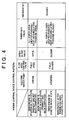
engine cooling device 1 according to the cooling device control process (Figs. 2 and 3) during start of the engine will be summarized. - If a condition [1] shown below is satisfied in starting the engine E, the
engine cooling device 1 is controlled through a preheat mode that will be described later. On the other hand, if one of conditions [2] to [4] shown below is satisfied in starting the engine E, theengine cooling device 1 is controlled through a coolant circulation stoppage mode that will be described later. - [1] That the engine E be started in a cold state (the engine coolant temperature THwe be lower than the cold-state criterion temperature THwL) and that preheat have not been completed (the drive period Tpm for the
electric water pump 15 be shorter than the predetermined period TpmX). - [2] That the engine E be started in a cold state (the engine coolant temperature THwe be lower than the cold-state criterion temperature THwL) and that preheat have been completed (the drive period Tpm for the
electric water pump 15 be equal to or longer than the predetermined period TpmX). - [3] That the engine E be started in a hot state (the engine coolant temperature THwe be equal to or higher than the cold-state criterion temperature THwL).
- [4] That the engine E have just been started (the fuel injection amount cumulative value FiA be smaller than the predetermined cumulative value FiX).
- In the preheat mode, (a) the flow
rate control valve 22 is fully opened, (b) the open-close valve 23 is opened, (c) all the ports of the three-way valve 24 are opened, and (d) theelectric water pump 15 is driven. Theengine cooling device 1 is controlled according to these patterns. - In the coolant circulation stoppage mode, (a) the
electric water pump 15 is stopped, (b) the flowrate control valve 22 is fully closed, (c) the open-close valve 23 is closed, and (d) all the ports of the three-way valve 24 are closed. Theengine cooling device 1 is controlled according to these patterns. - In any of the aforementioned respective control modes, the
thermostat 21 is basically held closed. - Referring now to Figs. 5 and 6, the operation and effect achieved by "the cooling device control process during start of the engine" (Figs. 2 and 3) will be described. Fig. 5 shows a pattern according to which coolant circulates when the
engine cooling device 1 is controlled through the preheat mode. Fig. 6 shows a pattern according to which coolant circulates when theengine cooling device 1 is controlled through the coolant circulation stoppage mode. In Figs. 5 and 6, cooling passages indicated by solid lines represent those through which coolant flows, arrows represent directions in which coolant flows, and cooling passages indicated by broken lines represent those through which coolant does not flow. - Referring to Fig. 5, the operation and effect achieved by the preheat mode will be described.
- When the
engine cooling device 1 is controlled through the preheat mode, theelectric water pump 15 causes coolant to circulate while the bypass passage, the throttle passage, and the heater passage as well as the heat-accumulating passage are open. Therefore, the coolant flows through all the cooling passages but the radiator passage. - At this moment, since coolant circulates via the heat-accumulating passage, the hot fluid stored in the heat-accumulating
container 16 is supplied to the engine E. Also, because the bypass passage, the throttle passage, and the heater passage are open, the flow resistance of coolant is reduced. - The flow rate of the hot fluid supplied to the engine E from the heat-accumulating
container 16 thereby increases, and the hot fluid in the heat-accumulatingcontainer 16 flows into the engine E at an early stage. Therefore, the warm-up of the engine E is promoted suitably. - Referring to Fig. 6, the operation and effect achieved by the coolant circulation stoppage mode will be described.
- When the
engine cooling device 1 is controlled through the coolant circulation stoppage mode, the radiator passage, the bypass passage, the throttle passage, the heater passage, and the heat-accumulating passage are closed. Therefore, coolant does not circulate through any of the cooling passages. - Thus, after hot fluid in the heat-accumulating
container 16 has been supplied into the interior of the engine E sufficiently, low-temperature coolant is not recirculated to the engine E. Therefore, the warm-up of the engine E is promoted more suitably. - When the engine E is started in a hot state and even if the engine E has just been started, low-temperature coolant is not recirculated to the engine E. Therefore, the warm-up of the engine E is promoted more suitably.
- Referring now to Fig. 7, one example of the control pattern of the
engine cooling device 1 according to "the cooling device control process during start of the engine" will be described. It is assumed that a request to start the engine E is detected through a vehicle-door opening operation based on a door open-close switch at a time t71 (see Fig. 7B). - If it is assumed herein that the engine coolant temperature THwe is lower than the cold-state criterion temperature THwL, the following operations (a) to (d) are performed (see Figs. 7C to 7F).
- That is, (a) the flow
rate control valve 22 is fully opened, (b) the open-close valve 23 is fully opened, (c) all the ports of the three-way valve 24 are opened, and (d) theelectric water pump 15 is driven. - Coolant is thereby caused to circulate with its flow resistance having been reduced. As a result, the hot fluid in the heat-accumulating
container 16 is supplied to the engine E at an early stage. - If it is assumed that the drive period Tpm for the
electric water pump 15 becomes equal to or longer than the predetermined period TpmX at a time t72, the following operations (a) to (d) are performed (see Figs. 7C to 7F). - That is, (a) the
electric water pump 15 is stopped, (b) the flowrate control valve 22 is fully closed, (c) the open-close valve 23 is fully closed, and (d) all the ports of the three-way valve 24 are closed. - The circulation of low-temperature coolant to the engine E is thereby stopped. As a result, the warm-up of the engine E is promoted suitably.
- If it is assumed that the engine E is started at a time t73, the flow
rate control valve 22, the open-close valve 23, and the three-way valve 24 are held closed until the fuel injection amount cumulative value FiA becomes equal to or larger than the predetermined cumulative value FiX (see Figs. 7A and 7C to 7E). - Because the circulation of coolant is thereby stopped, the warm-up of the engine E is promoted suitably.
- If it is assumed that the fuel injection amount cumulative FiA becomes equal to or larger than the predetermined cumulative value FiX at a time t74, the flow
rate control valve 22, the open-close valve 23, and the three-way valve 24 are thereafter controlled in accordance with the operational state of the engine E (Figs. 7C to 7E). - As described above in detail, beneficial effects as cited below are gained from the engine cooling device of the embodiment.
- (1) In the present embodiment, if hot fluid in the heat-accumulating
container 16 is supplied to the engine E on the ground that the engine coolant temperature THwe is lower than the cold-state criterion temperature THwL before the operation of starting the engine E, the bypass passage, the throttle passage, and the heater passage as well as the heat-accumulating passage are opened. The flow resistance of coolant is thereby reduced, and the hot fluid in the heat-accumulatingcontainer 16 is supplied to the engine E at an early stage. Therefore, the warm-up of the engine E can be promoted suitably. - (2) The aforementioned process (1) is performed before the operation of starting the engine E. Therefore, the engine E can be warmed up at an earlier stage.
- (3) In the present embodiment, if hot fluid in the heat-accumulating
container 16 is sufficiently supplied to the engine E before the operation of starting the engine E, the bypass passage, the throttle passage, the heater passage, and the heat-accumulating passage are closed. The circulation of low-temperature coolant to the engine E is thereby stopped. Therefore, the engine E can be suitably restrained from being lowered in temperature by low-temperature coolant. - (4) In the present embodiment, if the engine coolant temperature THwe is equal to or higher than the cold-state criterion temperature THwL before the operation of starting the engine E, the bypass passage, the throttle passage, the heater passage, and the heat-accumulating passage are closed. The circulation of low-temperature coolant is thereby stopped. Therefore, the engine E can be suitably restrained from being lowered in temperature by low-temperature coolant.
- (5) In the present embodiment, before the fuel injection amount cumulative value FiA becomes equal to or larger than the predetermined cumulative value FiX after the engine E has been started, the warm-up operation of the engine E is performed with the bypass passage, the throttle passage, the heater passage, and the throttle passage being closed. The circulation of coolant is thereby stopped. Therefore, the warm-up of the engine E can be promoted suitably.
- The aforementioned embodiment may be suitably modified and can also be implemented as embodiments that will be described hereinafter.
- In the aforementioned embodiment, the following determination process can also be added to the preheat process (Fig. 2). That is, it is determined immediately before or after step S101 "whether or not the temperature of coolant in the heat-accumulating container 16 (i.e., a heat-accumulating container coolant temperature THwt) is equal to or higher than a predetermined criterion temperature". In this case, (a) if the heat-accumulating container coolant temperature THwt is equal to or higher than the predetermined criterion temperature, the processings starting from step S102 are sequentially performed. On the other hand, (b) if the heat-accumulating container coolant temperature THwt is lower than the predetermined criterion temperature, the processing in step S106 is performed while omitting the processings in steps S102 to S105. The construction as described herein makes it possible to appropriately promote the warm-up of the engine E.
- In the aforementioned embodiment, the following determination processing can also be added to the preheat process (Fig. 2). That is, it is determined immediately before 'or after step S101 "whether or not the temperature of coolant in the heat-accumulating container 16 (i.e., the heat-accumulating container coolant temperature THwt) is equal to or higher than the engine coolant temperature THwe". In this case, (a) if the heat-accumulating container coolant temperature THwt is equal to or higher than the engine coolant temperature THwe, the processings starting from step S 102 are sequentially performed. On the other hand, (b) if the heat-accumulating container coolant temperature THwt is lower than the engine coolant temperature THwe, the processing in step S106 is performed while omitting the processings in steps S102 to S105. The construction as described herein prevents the low-temperature coolant stored in the heat-accumulating
container 16 from being supplied to the engine E. As a result, the warm-up performance of the engine E can be suitably restrained from deteriorating. - In the aforementioned embodiment, it is determined whether or not the engine coolant temperature THwe is lower than the cold-state criterion temperature THwL, and the processings in steps S102 to S105 (preheat) are performed when this condition is satisfied. However, the invention is not limited to this construction. Namely, it is also appropriate to omit the determination processing in step S101 and to perform the processings starting from step S102 every time the engine E is started. The construction as described herein eliminates the necessity to monitor the engine coolant temperature THwe prior to the implementation of preheat. In consequence, the preheat process is simplified.
- In the aforementioned embodiment, preheat is carried out on the ground that the engine coolant temperature THwe is lower than the cold-state criterion temperature THwL. However, the invention is not limited to this construction. Namely, preheat may also be carried out on the ground that the engine coolant temperature THwe is lower than an outside air temperature.
- In the aforementioned embodiment, the cold-state criterion temperature THwL is used in the determination processing of step S101. However, the cold-state criterion temperature THwL can be suitably changed to any temperature "that is equal to or higher than an outside air temperature and that is lower than a coolant temperature indicating the completion of warm-up of the engine E".
- In the aforementioned embodiment, it is determined that the engine E has just been started, on the ground that the fuel injection amount cumulative value FiA is smaller than the predetermined cumulative value FiX. However, the invention is not limited to this construction. Namely, it may also be determined that the engine E has just been started on the ground that the engine coolant temperature THwe is lower than the predetermined temperature.
- In the aforementioned embodiment, it is determined that the engine E has just been started, on the ground that the fuel injection amount cumulative value FiA is smaller than the predetermined cumulative value FiX. However, the invention is not limited to this construction. Namely, it may also be determined that the engine E has just been started, on the ground that the elapsed time after completion of the start of the engine E is shorter than a predetermined elapsed time.
- In the aforementioned embodiment, a request to start the engine E can be detected on the basis of the condition that "the changeover position of the ignition switch be shifted to "ON"" or the condition that "the door be opened through the door open-close switch of the vehicle". However, the detection of a request to start the engine can be determined on the basis of other suitable conditions as well as the conditions exemplified in the aforementioned embodiment. For instance, a request to start the engine may also be detected on the basis of a condition "that the changeover position of the ignition switch be shifted to "START"".
- In the aforementioned embodiment, the open-
close valve 23 is opened to open the throttle passage if preheat has not been completed in starting the engine E in a cold state. However, the invention is not limited to this construction. Namely, the open-close valve 23 is closed even if preheat has not been completed in starting the engine E in a cold state. It is also appropriate that the throttle valve be thereby closed. - In the aforementioned embodiment, if preheat has not been completed in starting the engine E in a cold state, the flow
rate control valve 22 is fully opened to open the bypass passage. However, the invention is not limited to this construction. Namely, if preheat has not been completed in starting the engine E in a cold state, the flowrate control valve 22 may also be set at any opening between its maximum opening and its minimum opening to open the bypass passage. In short, the control pattern of the flow rate control valve can be suitably changed as long as the flow rate of coolant flowing through the bypass passage is increased when the coolant is caused to circulate through the heat-accumulating circuit in starting the engine E in a cold state. - In the aforementioned embodiment, if preheat has not been completed in starting the engine E in a cold state, the first and second ports P1 and P2 of the three-
way valve 24 are opened to open the heater passage. However, the invention is not limited to this construction. The heater passage may also be closed by closing the second port P2 of the three-way valve 24 if preheat has not been completed in starting the engine E in a cold state. - In the aforementioned embodiment, the
thermostat 21 that operates in accordance with the temperature of coolant is used. However, the invention is not limited to this construction. It is also possible to employ an electronic thermostat capable of electrically controlling the release state of a valve. In the construction as described herein, the electronic thermostat is opened to open the radiator passage if preheat has not been completed in starting the engine E in a cold state, whereby the flow resistance of coolant can further be reduced. If any one of the above-mentioned conditions (2) to (4) is satisfied, the recirculation of low-temperature coolant to the engine E can be avoided by closing the electronic thermostat. - In the aforementioned embodiment, the throttle passage is provided with the open-
close valve 23. However, the invention is not limited to this construction. Namely, a flow rate control valve whose opening is continuously variable can also be provided in place of the open-close valve 23. - In the aforementioned embodiment, the bypass passage is provided with the flow
rate control valve 22. However, the invention is not limited to this construction. Namely, an open-close valve that can be switched to either its open state or its closed state can also be provided in place of the flowrate control valve 22. - In the aforementioned embodiment, the preheat process is started in response to a request to start the engine E. However, the invention is not limited to this construction. Namely, the preheat process may also be started in response to the start of the engine E. The construction as described herein makes it possible to start the coolant circulation stoppage process after the preheat process has been completed.
- In the aforementioned embodiment, the preheat process is started in response to a request to start the engine E. However, the invention is not limited to this construction. The preheat process may also be started immediately after the engine E has been started. The construction as described herein makes it possible to start the coolant circulation stoppage process after the preheat process has been completed.
- In the aforementioned embodiment, the heat-accumulating passage is connected to or disconnected from the cooling circuit through control of the three-
way valve 24. However, the invention is not limited to this construction. Namely, it is also appropriate that the heat-accumulating passage be provided with an open-close valve, a flow rate control valve or the like and be connected to or disconnected from the cooling circuit through control of the open-close valve, the flow rate control valve or the like. - In the aforementioned embodiment, the invention is embodied on the assumption that the
engine cooling device 1 exemplified in Fig. 1 is to be used. However, the construction of the engine cooling device is not limited to the construction exemplified in the embodiment but can be any suitable construction. In short, as long as the cooling device is provided with a cooling circuit composed of a radiator passage, a bypass passage, and a flow rate control valve for controlling the flow rate of coolant flowing through the bypass passage, and with a heat-accumulating passage that includes a heat-accumulating container and that constitutes a heat-accumulating circuit by being selectively connected to the cooling circuit, it is possible to provide the cooling device with any construction. - In the aforementioned embodiment, the
engine cooling device 1 is controlled during start of the engine E through the cooling device control process performed in starting the engine. However, the cooling device control process performed in starting the engine is not limited to the construction exemplified in the embodiment. In short, the control pattern can be suitably modified as long as it is constructed such that a heat-accumulating circuit is completed by connecting a heat-accumulating passage to a cooling circuit in starting an engine, that a bypass passage is opened through control of a control valve, that the heat-accumulating passage is disconnected from the cooling circuit after coolant in a heat-accumulating container has been supplied to the engine, and that the bypass passage is closed through control of the control valve. - While the invention has been described with reference to the exemplary embodiments thereof, it is to be understood that the invention is not limited to the exemplary embodiments or constructions. To the contrary, the invention is intended to cover various modifications and equivalent arrangements. In addition, while the various elements of the exemplary embodiments are shown in various combinations and configurations, which are exemplary, other combinations and configurations, including more, less or only a single element, are also within the spirit and scope of the invention.
The invention provides an engine cooling device capable of suitably promoting the warm-up of an engine. This device comprises a cooling circuit and a heat-accumulating passage. The cooling circuit is composed of a radiator passage, a bypass passage, and a flowrate control valve 22 for controlling the flow rate of coolant flowing through the bypass passage. The heat-accumulating passage is provided with a heat-accumulatingcontainer 16, and constitutes a heat-accumulating circuit for causing coolant in the heat-accumulatingcontainer 16 to circulate via an engine E. The cooling device completes the heat-accumulating circuit by connecting the heat-accumulating passage to the cooling circuit to supply the cooling medium in the heat-accumulatingcontainer 16 to the body of the engine E, opens the flowrate control valve 22 to increase a flow rate of cooling medium flowing through the bypass passage, then disconnects the heat-accumulating passage from the cooling circuit, and closes the flowrate control valve 22.
Claims (12)
- An engine cooling device having a cooling circuit that is so constructed as to include a radiator passage for causing cooling medium flowing from a body of an engine to flow into the body of the engine via a radiator, a bypass passage for causing cooling medium flowing out from the body of the engine to flow into the body of the engine without flowing via the radiator, and a control valve for controlling a flow rate of cooling medium flowing through the bypass passage, and a heat-accumulating passage that is provided with a heat-accumulating container for storing the cooling medium in a thermally insulated state and that constitutes a heat-accumulating circuit for causing the cooling medium in the heat-accumulating container to circulate via the body of the engine by being selectively connected to the cooling circuit, characterized by comprising:control means that i) completes the heat-accumulating circuit by connecting the heat-accumulating passage to the cooling circuit to supply the cooling medium in the heat-accumulating container to the body of the engine and opens the control valve to increase a flow rate of cooling medium flowing through the bypass passage, and then ii) disconnects the heat-accumulating passage from the cooling circuit and closes the control valve.
- The cooling device according to claim 1, wherein
the control means i) completes the heat-accumulating circuit by connecting the heat-accumulating passage to the cooling circuit and opens the control valve prior to an operation of starting the engine, and ii) disconnects the heat-accumulating passage from the cooling circuit and closes the control valve immediately after the engine has been started. - The cooling device according to claim 2, wherein
the control means determines that the engine has just been started, if cooling medium for cooling the body of the engine is at a temperature lower than a predetermined temperature. - The cooling device according to claim 2, wherein
the control means determines that the engine has just been started, unless a predetermined time has elapsed since completion of the starting of the engine. - The cooling device according to any one of claims 1 to 4, wherein
the cooling circuit is so constructed as to further include a throttle passage for causing cooling medium flowing out from the body of the engine to flow into the body of the engine via a throttle body, and a throttle open-close valve for opening and closing the throttle passage, and
the control means opens the throttle open-close valve in supplying cooling medium in the heat-accumulating container to the body of the engine through the heat-accumulating circuit by connecting the heat-accumulating passage to the cooling circuit, and closes the throttle open-close valve in disconnecting the heat-accumulating passage from the cooling circuit. - The cooling device according to any one of claims 1 to 5, wherein
the cooling circuit is so constructed as to further include a heater passage for causing cooling medium flowing out from the body of the engine to flow into the body of the engine via a heater core, and a heater open-close valve for opening and closing the heater passage, and
the control means opens the heater open-close valve in supplying cooling medium in the heat-accumulating container to the body of the engine through the heat-accumulating circuit by connecting the heat-accumulating passage to the cooling circuit, and closes the heater open-close valve in disconnecting the heat-accumulating passage from the cooling circuit. - The cooling device according to any one of claims 1. to 6, wherein
the control means prohibits the heat-accumulating passage from being connected to the cooling circuit if cooling medium in the heat-accumulating container is at a temperature lower than a predetermined temperature. - The cooling device according to claim 7, wherein
the predetermined temperature is a temperature of coolant for cooling the body of the engine. - The cooling device according to any one of claims 1 to 8, wherein
the control means connects the heat-accumulating passage to the cooling circuit if cooling medium for cooling the body of the engine is at a temperature lower than a predetermined temperature. - The cooling device according to claim 9, wherein
the predetermined temperature is a cold-state criterion temperature. - The cooling device according to claim 9, wherein
the predetermined temperature is an outside air temperature. - The cooling device according to any one of claims 1 to 11, wherein
the control means closes the radiator passage both in opening the control valve and in closing the control valve.
Applications Claiming Priority (2)
| Application Number | Priority Date | Filing Date | Title |
|---|---|---|---|
| JP2003096645 | 2003-03-31 | ||
| JP2003096645A JP4103663B2 (en) | 2003-03-31 | 2003-03-31 | Engine cooling system |
Publications (2)
| Publication Number | Publication Date |
|---|---|
| EP1471226A2 true EP1471226A2 (en) | 2004-10-27 |
| EP1471226A3 EP1471226A3 (en) | 2009-08-12 |
Family
ID=32959548
Family Applications (1)
| Application Number | Title | Priority Date | Filing Date |
|---|---|---|---|
| EP20040007658 Withdrawn EP1471226A3 (en) | 2003-03-31 | 2004-03-30 | Engine cooling device |
Country Status (3)
| Country | Link |
|---|---|
| US (1) | US6915763B2 (en) |
| EP (1) | EP1471226A3 (en) |
| JP (1) | JP4103663B2 (en) |
Cited By (1)
| Publication number | Priority date | Publication date | Assignee | Title |
|---|---|---|---|---|
| EP2345803A1 (en) * | 2009-12-17 | 2011-07-20 | Volkswagen Aktiengesellschaft | Coolant circuit of a combustion engine and a work method for operating same |
Families Citing this family (26)
| Publication number | Priority date | Publication date | Assignee | Title |
|---|---|---|---|---|
| JP4049045B2 (en) * | 2003-07-28 | 2008-02-20 | トヨタ自動車株式会社 | Engine system with heat storage device |
| DE10336599B4 (en) * | 2003-08-08 | 2016-08-04 | Daimler Ag | Method for controlling a thermostat in a cooling circuit of an internal combustion engine |
| US7140330B2 (en) * | 2004-07-13 | 2006-11-28 | Modine Manufacturing Company | Coolant system with thermal energy storage and method of operating same |
| US7886988B2 (en) * | 2004-10-27 | 2011-02-15 | Ford Global Technologies, Llc | Switchable radiator bypass valve set point to improve energy efficiency |
| US7533635B2 (en) * | 2006-03-07 | 2009-05-19 | International Truck Intellectual Property Company, Llc | Method and device for a proactive cooling system for a motor vehicle |
| US7467605B2 (en) * | 2006-05-26 | 2008-12-23 | Visteon Global Technologies, Inc. | Thermal energy recovery and management system |
| US20080115747A1 (en) * | 2006-10-31 | 2008-05-22 | International Engine Intellectual Property Company, Llc | Coolant controller for an internal combustion engine |
| JP5580151B2 (en) | 2010-09-17 | 2014-08-27 | 富士重工業株式会社 | Engine waste heat recovery and cooling system |
| US8459389B2 (en) * | 2010-12-30 | 2013-06-11 | Hyundai Motor Company | Integrated pump, coolant flow control and heat exchange device |
| US20120168138A1 (en) * | 2010-12-30 | 2012-07-05 | Hyundai Motor Company | Integrated pump, coolant flow control and heat exchange device |
| JP5821440B2 (en) * | 2011-09-08 | 2015-11-24 | いすゞ自動車株式会社 | Engine cooling system |
| US8689617B2 (en) | 2012-03-30 | 2014-04-08 | Ford Global Technologies, Llc | Engine cooling system control |
| US8683854B2 (en) | 2012-03-30 | 2014-04-01 | Ford Global Technologies, Llc | Engine cooling system control |
| US9341105B2 (en) | 2012-03-30 | 2016-05-17 | Ford Global Technologies, Llc | Engine cooling system control |
| US9022647B2 (en) | 2012-03-30 | 2015-05-05 | Ford Global Technologies, Llc | Engine cooling system control |
| JP6013022B2 (en) * | 2012-05-14 | 2016-10-25 | 日産自動車株式会社 | Cooling control device for internal combustion engine and cooling control method therefor |
| DE102012210320B3 (en) * | 2012-06-19 | 2013-09-26 | Ford Global Technologies, Llc | Liquid-cooled combustion engine for vehicle, has steering valve arranged in connecting line between pump and vent tank and providing enlarged passage area as result of reduced pressure refrigerant in work position |
| US9796244B2 (en) * | 2014-01-17 | 2017-10-24 | Honda Motor Co., Ltd. | Thermal management system for a vehicle and method |
| DE102014106362A1 (en) * | 2014-05-07 | 2015-11-12 | Bayerische Motoren Werke Aktiengesellschaft | Method for monitoring the opening state of a control valve of a coolant circuit of an internal combustion engine and device therefor |
| US10253679B2 (en) * | 2015-08-04 | 2019-04-09 | Honda Motor Co., Ltd. | Vehicle thermal management system, and methods of use and manufacture thereof |
| KR101745159B1 (en) * | 2015-10-28 | 2017-06-08 | 현대자동차주식회사 | Cooling water supplying apparatus and method of throttle body |
| US11085356B2 (en) * | 2018-03-01 | 2021-08-10 | Nio Usa, Inc. | Thermal management coolant valves and pumps modular combination |
| US10843550B2 (en) | 2018-08-21 | 2020-11-24 | Nio Usa, Inc. | Thermal management system with two pumps and three loops |
| DE102020119674B4 (en) * | 2020-07-27 | 2026-01-15 | Dr. Ing. H.C. F. Porsche Aktiengesellschaft | Method for operating a drive system of a plug-in hybrid vehicle |
| CN112963283B (en) * | 2021-03-09 | 2022-11-15 | 徐工集团工程机械股份有限公司道路机械分公司 | Engine preheating system and preheating method thereof |
| CN115143007A (en) * | 2021-03-30 | 2022-10-04 | 广州汽车集团股份有限公司 | A temperature control module control method, device and computer storage medium |
Citations (2)
| Publication number | Priority date | Publication date | Assignee | Title |
|---|---|---|---|---|
| DE2916216A1 (en) | 1979-04-21 | 1980-11-06 | Bosch Gmbh Robert | Preheating system for IC engine - stores waste heat as latent heat and uses salt solution changing from crystalline to liquid form releasing heat to oil circuit |
| JPH07180554A (en) | 1993-12-21 | 1995-07-18 | Aisin Seiki Co Ltd | Engine cooling system |
Family Cites Families (12)
| Publication number | Priority date | Publication date | Assignee | Title |
|---|---|---|---|---|
| US2016179A (en) * | 1932-10-25 | 1935-10-01 | Rosenqvist Viktor | Cooling system for engines |
| US5435277A (en) * | 1993-03-12 | 1995-07-25 | Nobuo Takahashi | Hot water injection apparatus for water cooling engine |
| SE9500964L (en) * | 1994-11-14 | 1996-02-26 | Jens Thurfjell | Heat storage device at a liquid-cooled internal combustion engine |
| JP3525538B2 (en) * | 1995-03-08 | 2004-05-10 | 株式会社デンソー | Cooling system for internal combustion engine for vehicles |
| JP3564843B2 (en) * | 1995-05-26 | 2004-09-15 | 株式会社デンソー | Engine warm-up device for vehicles |
| JPH1077839A (en) | 1996-08-30 | 1998-03-24 | Denso Corp | Cooling water control valve and cooling water circuit for internal combustion engine |
| US6532911B2 (en) * | 2000-07-26 | 2003-03-18 | Toyota Jidosha Kabushiki Kaisha | Internal combustion engine having heat accumulator, control of heat supply system and control method of internal combustion engine |
| JP2002188442A (en) * | 2000-10-11 | 2002-07-05 | Denso Corp | Thermal storage tank |
| JP4432272B2 (en) * | 2001-04-09 | 2010-03-17 | トヨタ自動車株式会社 | Internal combustion engine equipped with a heat storage device |
| FR2825750B1 (en) * | 2001-06-12 | 2003-11-28 | Peugeot Citroen Automobiles Sa | IMPROVED THERMAL REGULATION DEVICE WITH ENERGY STORAGE FOR MOTOR VEHICLE |
| JP3867550B2 (en) * | 2001-07-04 | 2007-01-10 | 株式会社日本自動車部品総合研究所 | Heat storage tank |
| JP4513245B2 (en) * | 2001-09-06 | 2010-07-28 | 株式会社デンソー | Heat storage tank |
-
2003
- 2003-03-31 JP JP2003096645A patent/JP4103663B2/en not_active Expired - Fee Related
-
2004
- 2004-03-23 US US10/806,412 patent/US6915763B2/en not_active Expired - Fee Related
- 2004-03-30 EP EP20040007658 patent/EP1471226A3/en not_active Withdrawn
Patent Citations (2)
| Publication number | Priority date | Publication date | Assignee | Title |
|---|---|---|---|---|
| DE2916216A1 (en) | 1979-04-21 | 1980-11-06 | Bosch Gmbh Robert | Preheating system for IC engine - stores waste heat as latent heat and uses salt solution changing from crystalline to liquid form releasing heat to oil circuit |
| JPH07180554A (en) | 1993-12-21 | 1995-07-18 | Aisin Seiki Co Ltd | Engine cooling system |
Cited By (1)
| Publication number | Priority date | Publication date | Assignee | Title |
|---|---|---|---|---|
| EP2345803A1 (en) * | 2009-12-17 | 2011-07-20 | Volkswagen Aktiengesellschaft | Coolant circuit of a combustion engine and a work method for operating same |
Also Published As
| Publication number | Publication date |
|---|---|
| JP2004301061A (en) | 2004-10-28 |
| EP1471226A3 (en) | 2009-08-12 |
| US6915763B2 (en) | 2005-07-12 |
| JP4103663B2 (en) | 2008-06-18 |
| US20040187805A1 (en) | 2004-09-30 |
Similar Documents
| Publication | Publication Date | Title |
|---|---|---|
| EP1471226A2 (en) | Engine cooling device | |
| EP1952000B1 (en) | Engine cooling medium circulation device | |
| US7370612B2 (en) | Internal combustion engine cooling system | |
| JP4432272B2 (en) | Internal combustion engine equipped with a heat storage device | |
| JP3767803B2 (en) | Fuel supply device | |
| JP2009243387A (en) | Engine exhaust heat recovery system | |
| JP4100220B2 (en) | Engine cooling system | |
| JP3820977B2 (en) | Hybrid system heat storage device | |
| JP2002021560A (en) | Internal combustion engine having heat storage device | |
| JP2003003843A (en) | Internal combustion engine with heat storage device | |
| JP4001041B2 (en) | Engine cooling system | |
| JP4239368B2 (en) | Internal combustion engine having a heat storage device | |
| US10844771B2 (en) | Cooling apparatus of engine | |
| JP4069790B2 (en) | Engine cooling system | |
| JP3906745B2 (en) | Cooling device for internal combustion engine | |
| JP4238543B2 (en) | Internal combustion engine equipped with a heat storage device | |
| JP3906748B2 (en) | Cooling device for internal combustion engine | |
| JP2001098941A (en) | Internal combustion engine cooling system | |
| CN220622055U (en) | Engine cold start system and vehicle | |
| JP3906817B2 (en) | Engine cooling system | |
| JP2008082225A (en) | Engine cooling system | |
| JP4214890B2 (en) | Engine cooling system | |
| JP4098023B2 (en) | Cooling device for internal combustion engine | |
| JP4572472B2 (en) | Engine cooling system | |
| JP2005030214A (en) | Internal combustion engine equipped with a heat storage device |
Legal Events
| Date | Code | Title | Description |
|---|---|---|---|
| PUAI | Public reference made under article 153(3) epc to a published international application that has entered the european phase |
Free format text: ORIGINAL CODE: 0009012 |
|
| 17P | Request for examination filed |
Effective date: 20040330 |
|
| AK | Designated contracting states |
Kind code of ref document: A2 Designated state(s): AT BE BG CH CY CZ DE DK EE ES FI FR GB GR HU IE IT LI LU MC NL PL PT RO SE SI SK TR |
|
| AX | Request for extension of the european patent |
Extension state: AL LT LV MK |
|
| PUAL | Search report despatched |
Free format text: ORIGINAL CODE: 0009013 |
|
| AK | Designated contracting states |
Kind code of ref document: A3 Designated state(s): AT BE BG CH CY CZ DE DK EE ES FI FR GB GR HU IE IT LI LU MC NL PL PT RO SE SI SK TR |
|
| AX | Request for extension of the european patent |
Extension state: AL LT LV MK |
|
| RIC1 | Information provided on ipc code assigned before grant |
Ipc: F01P 7/16 20060101ALI20090703BHEP Ipc: F02N 17/06 20060101ALI20090703BHEP Ipc: F01P 11/20 20060101AFI20090703BHEP |
|
| 17Q | First examination report despatched |
Effective date: 20090928 |
|
| AKX | Designation fees paid |
Designated state(s): DE FR GB IT |
|
| RAP1 | Party data changed (applicant data changed or rights of an application transferred) |
Owner name: TOYOTA JIDOSHA KABUSHIKI KAISHA |
|
| GRAP | Despatch of communication of intention to grant a patent |
Free format text: ORIGINAL CODE: EPIDOSNIGR1 |
|
| RIC1 | Information provided on ipc code assigned before grant |
Ipc: F02N 19/10 20100101ALI20180427BHEP Ipc: F01P 7/16 19680901ALI20180427BHEP Ipc: F01P 11/20 19680901AFI20180427BHEP |
|
| INTG | Intention to grant announced |
Effective date: 20180606 |
|
| RIC1 | Information provided on ipc code assigned before grant |
Ipc: F01P 11/20 20060101AFI20180427BHEP Ipc: F01P 7/16 20060101ALI20180427BHEP Ipc: F02N 19/10 20100101ALI20180427BHEP |
|
| STAA | Information on the status of an ep patent application or granted ep patent |
Free format text: STATUS: THE APPLICATION IS DEEMED TO BE WITHDRAWN |
|
| 18D | Application deemed to be withdrawn |
Effective date: 20181017 |