EP1471213A2 - Camshaft rotational detection structure - Google Patents
Camshaft rotational detection structure Download PDFInfo
- Publication number
- EP1471213A2 EP1471213A2 EP20040009301 EP04009301A EP1471213A2 EP 1471213 A2 EP1471213 A2 EP 1471213A2 EP 20040009301 EP20040009301 EP 20040009301 EP 04009301 A EP04009301 A EP 04009301A EP 1471213 A2 EP1471213 A2 EP 1471213A2
- Authority
- EP
- European Patent Office
- Prior art keywords
- camshaft
- thrust flange
- cam
- cam thrust
- detection structure
- Prior art date
- Legal status (The legal status is an assumption and is not a legal conclusion. Google has not performed a legal analysis and makes no representation as to the accuracy of the status listed.)
- Granted
Links
Images



Classifications
-
- F—MECHANICAL ENGINEERING; LIGHTING; HEATING; WEAPONS; BLASTING
- F02—COMBUSTION ENGINES; HOT-GAS OR COMBUSTION-PRODUCT ENGINE PLANTS
- F02D—CONTROLLING COMBUSTION ENGINES
- F02D35/00—Controlling engines, dependent on conditions exterior or interior to engines, not otherwise provided for
-
- F—MECHANICAL ENGINEERING; LIGHTING; HEATING; WEAPONS; BLASTING
- F01—MACHINES OR ENGINES IN GENERAL; ENGINE PLANTS IN GENERAL; STEAM ENGINES
- F01L—CYCLICALLY OPERATING VALVES FOR MACHINES OR ENGINES
- F01L1/00—Valve-gear or valve arrangements, e.g. lift-valve gear
- F01L1/02—Valve drive
- F01L1/04—Valve drive by means of cams, camshafts, cam discs, eccentrics or the like
- F01L1/047—Camshafts
-
- F—MECHANICAL ENGINEERING; LIGHTING; HEATING; WEAPONS; BLASTING
- F01—MACHINES OR ENGINES IN GENERAL; ENGINE PLANTS IN GENERAL; STEAM ENGINES
- F01L—CYCLICALLY OPERATING VALVES FOR MACHINES OR ENGINES
- F01L1/00—Valve-gear or valve arrangements, e.g. lift-valve gear
- F01L1/02—Valve drive
- F01L1/04—Valve drive by means of cams, camshafts, cam discs, eccentrics or the like
- F01L1/047—Camshafts
- F01L1/053—Camshafts overhead type
- F01L2001/0537—Double overhead camshafts [DOHC]
-
- F—MECHANICAL ENGINEERING; LIGHTING; HEATING; WEAPONS; BLASTING
- F01—MACHINES OR ENGINES IN GENERAL; ENGINE PLANTS IN GENERAL; STEAM ENGINES
- F01L—CYCLICALLY OPERATING VALVES FOR MACHINES OR ENGINES
- F01L1/00—Valve-gear or valve arrangements, e.g. lift-valve gear
- F01L1/34—Valve-gear or valve arrangements, e.g. lift-valve gear characterised by the provision of means for changing the timing of the valves without changing the duration of opening and without affecting the magnitude of the valve lift
- F01L1/344—Valve-gear or valve arrangements, e.g. lift-valve gear characterised by the provision of means for changing the timing of the valves without changing the duration of opening and without affecting the magnitude of the valve lift changing the angular relationship between crankshaft and camshaft, e.g. using helicoidal gear
- F01L1/3442—Valve-gear or valve arrangements, e.g. lift-valve gear characterised by the provision of means for changing the timing of the valves without changing the duration of opening and without affecting the magnitude of the valve lift changing the angular relationship between crankshaft and camshaft, e.g. using helicoidal gear using hydraulic chambers with variable volume to transmit the rotating force
- F01L2001/34423—Details relating to the hydraulic feeding circuit
- F01L2001/34426—Oil control valves
- F01L2001/34433—Location oil control valves
-
- F—MECHANICAL ENGINEERING; LIGHTING; HEATING; WEAPONS; BLASTING
- F01—MACHINES OR ENGINES IN GENERAL; ENGINE PLANTS IN GENERAL; STEAM ENGINES
- F01L—CYCLICALLY OPERATING VALVES FOR MACHINES OR ENGINES
- F01L2820/00—Details on specific features characterising valve gear arrangements
- F01L2820/04—Sensors
- F01L2820/041—Camshafts position or phase sensors
-
- Y—GENERAL TAGGING OF NEW TECHNOLOGICAL DEVELOPMENTS; GENERAL TAGGING OF CROSS-SECTIONAL TECHNOLOGIES SPANNING OVER SEVERAL SECTIONS OF THE IPC; TECHNICAL SUBJECTS COVERED BY FORMER USPC CROSS-REFERENCE ART COLLECTIONS [XRACs] AND DIGESTS
- Y10—TECHNICAL SUBJECTS COVERED BY FORMER USPC
- Y10T—TECHNICAL SUBJECTS COVERED BY FORMER US CLASSIFICATION
- Y10T74/00—Machine element or mechanism
- Y10T74/21—Elements
- Y10T74/2101—Cams
Definitions
- the present invention relates to a camshaft rotational detection structure. More particularly, the present invention relates to a camshaft rotational detection structure configured to detect the rotational angle of a camshaft to which rotation is transmitted from the crankshaft of an engine through a cam sprocket mechanism.
- DOHC multi-cylinder engines two parallel camshafts for operating the intake valves and exhaust valves are arranged on the cylinder head of the engine and a sensor is mounted on each camshaft to detect the camshaft rotational angle for the purposes of identifying the cylinders and controlling the valve timing.
- An example of a mounting structure for this kind of sensor is presented in Japanese Laid-Open Patent Publication No. 2001-329885 (page 4 and Figure 3).
- the sensor mounting structure described in that document has a first shaft bearing and a second shaft bearing provided on the camshaft near the cam sprocket mechanism and thrust bearings for restricting axial movement of the camshaft provided axially in front of and behind the first shaft bearing.
- a shutter (detection target) is also provided between the first and second shaft bearings separately from the thrust bearings, and the sensor is arranged facing opposite the shutter.
- the shutter detection target
- the camshaft is longer and heavier than it might otherwise be.
- the camshaft is longer and heavier than it might otherwise be.
- An object of the present invention is to provide a camshaft rotational detection structure that can improve the precision with which the camshaft rotational angle is detected.
- Another object of the present invention is to provide a camshaft rotational detection structure that does not increase the weight of the camshaft.
- a camshaft rotational detection structure in accordance with the present invention basically comprises a camshaft, a cam thrust flange, a detection target and a sensor.
- the camshaft has a cam sprocket mechanism attachment end;
- the cam thrust flange is disposed on the camshaft near the cam sprocket mechanism attachment end.
- the cam thrust flange is configured and arranged to restrict axial movement of the camshaft.
- the detection target is disposed on the cam thrust flange.
- the sensor is configured and arranged to face opposite the detection target and to detect rotation of the camshaft.
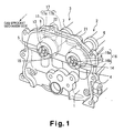
- Figure 1 is a partial perspective view of an engine cylinder head for an inline multi-cylinder DOHC engine having a camshaft rotational detection structure in accordance with the present invention
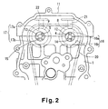
- Figure 2 is a partial front elevational view of the cylinder head illustrated in Figure 1 with the camshaft rotational detection structure in accordance with the present invention
- Figure 3 is a partial top plan view of the cylinder head illustrated in Figure 1 with selected portions removed to show the camshaft rotational detection structure in accordance with the present invention
- Figure 4 is a partial side elevational view of the cylinder head illustrated in Figure 1 with the camshaft rotational detection structure in accordance with the present invention
- FIG. 5 is an enlarged partial perspective view of the camshaft illustrated in Figure 1 with the camshaft rotational detection structure in accordance with the present invention
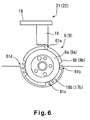
- Figure 6 is a partial front elevational view illustrating the positioning relationship between the cam thrust flange and the sensor illustrated in Figure 1 for the camshaft rotational detection structure in accordance with the present invention
- Figure 7 is a partial top plan view illustrating the positioning relationship between the cam thrust flange and the cylinder head illustrated in Figure 1 for the camshaft rotational detection structure in accordance with the present invention.
- Figure 8 is an exploded partial perspective view of an assembled shaft in accordance with a second embodiment of the present invention.
- an engine cylinder head 1 is illustrated for an inline multi-cylinder dual over head cam (DOHC) engine having a camshaft rotational detection structure in accordance with a first embodiment of the present invention.
- An intake camshaft 2 and an exhaust camshaft 3 are arranged on the upper surface of the cylinder head 1 in such a manner as to be substantially parallel to each other and parallel to a crankshaft (not shown).
- one end of each of the camshafts 2 and 3 has a cam sprocket mechanism 20 mounted thereto in order to receive rotational input from the crankshaft.
- the intake camshaft 2 comprises a rod-shaped shaft main body 4, a plurality of cams 6 provided on the outside surface of the shaft main body 4, and a cam thrust flange 8 for restricting the axial movement of the shaft main body 4.
- the exhaust camshaft 3 comprises a rod-shaped shaft main body 5, a plurality of cams 7 provided on the outside surface of the shaft main body 5, and a cam thrust flange 9 for restricting the axial movement of the shaft main body 5.
- the cams 6 and the thrust flange 8 are formed integrally with the shaft main body 4 as a one-piece, unitary member, e.g. the cams 6 and the thrust flange 8 are machined or cast on the outside surface of the shaft main body 4.
- the cams 7 and the cam thrust flange 9 are formed integrally with on the shaft main body 5 as a one-piece, unitary member in the same manner as the intake camshaft 2.
- the upper surface of the cylinder head 1 has a plurality of lower shaft bearing parts 14 and 15 that are integrally formed on the upper surface of the cylinder head 1.
- the inside of each of the lower shaft bearing parts 14 and 15 has a semi-cylindrical bearing surface for supporting the lower half of one of the shaft main bodies 4 and 5, respectively.
- the camshafts 2 and 3 are rotatably retained on the upper surface of the cylinder head 1 by a plurality of cam brackets 10 and an end cam bracket 11.
- the cam brackets 10 and 11 are mounted to the cylinder head 1 to overlie the lower shaft bearing parts 14 and 15.
- the cam brackets 10 and 11 are each provided with upper shaft bearing parts 12 and 13 having semi-cylindrical bearing surfaces 16a and 16b for supporting the upper halves of the shaft main bodies 4 and 5.
- the upper shaft bearing parts 12 and 13 are arranged to correspond to the lower shaft bearing parts 14 and 15.
- the shaft main body 4 is supported in a freely rotatable manner by the bearing surfaces of the lower shaft bearing parts 14 and the upper shaft bearing parts 12.
- the shaft main body 5 is supported in a freely rotatable manner by the bearing surfaces of the lower shaft bearing parts 15 and the upper shaft bearing parts 13.
- the upper surface of the cylinder head 1 has a pair of semi-circular grooves 16b and 17b into which the lower halves of the cam thrust flanges 8 and 9 are received , respectively.
- the semi-circular grooves 16b and 17b are formed in the bearing surfaces of the lower shaft bearing parts 14 and 15 that are disposed at the ends near the cam sprocket mechanisms 20. In other words, the lower shaft bearing parts 14 and 15 are positioned farther to the outside than the cams 6 and 7 that are closest to the cam sprocket mechanisms 20.
- two semi-circular grooves 16a and 17a are formed in the cam bracket 11 that receive the upper half of the cam thrust flanges 8 and 9, respectively.
- the semi-circular grooves 16a and 17a are formed in the bearing surfaces of the upper shaft bearing parts 12 and 13 provided on the cam bracket 11.
- the semi-circular grooves 16a and 17a are arranged to correspond to the grooves 16b and 17b formed in the lower shaft bearing parts 14 and 15.
- the upper and lower grooves 16a and 16b form an annular groove 16, while the upper and lower grooves 17a and 17b form annular groove 17.
- the lower halves of the cam thrust flanges 8 and 9 are inserted into the grooves 16b and 17b when the camshafts 2 and 3 are arranged on the shaft bearing surfaces of the lower shaft bearing parts 14 and 15.
- the upper halves of the cam thrust flanges 8 and 9 are inserted into the grooves 16a and 17a when the cam bracket 11 is mounted onto the lower shaft bearing parts 14 and 15.
- the cam thrust flanges 8 and 9 are disposed into the annular grooves 16 and 17 in a freely sliding or rotating manner.
- the cam bracket 11 that overlie the lower shaft bearing parts 14 and 15 positioned closest to the cam sprocket mechanisms 20 supports a pair of sensors or sensing devices 21.
- this cam bracket 11 comprises a bracket main body section 11a and a cover section 11b.
- the bracket main body section 11a is configured and arranged to mount a chain cover (not shown) thereon.
- the cover section 11b extends from the bottom of the bracket main body 11a in the vertical direction and faces axially inward toward the cylinder head 1.
- the sensor or sensing devices 21 are mounted to the cover sections 11b above the camshafts 2 and 3 to detect the rotational angles of the cams 6 and 7, respectively.
- Each of the sensors 21 comprises a mounting flange 18 and a sensor main unit 19.
- Each of the cover sections 11b has a sensor mounting section 21a with an insertion hole that opens above the cam thrust flange 8 or 9. The sensor main unit 19 is inserted into the insertion hole facing downward and the mounting flange 18 is fixed to the cover section 11b.
- the cam thrust flanges 8 and 9 are formed in the shape of a circular disk, as shown in Figures 5 to 7.
- the cam thrust flange 8 comprises an outer circumferential section 8a and an inner circumferential section 8b whose thicknesses are different.
- the outer circumferential section 8a is thinner than the inner circumferential section 8b such that a step is formed such the full circumference between the outer circumferential section 8a and the inner circumferential section 8b on both lateral faces of the cam thrust flange 8.
- the outside diameter of the outer circumferential section 8a is larger than the outside diameters of the shaft main body 4, the cams 6, and all other components of the camshaft 2.
- the width of the groove 16b width of annular groove 16
- the inner circumferential section 8b forms a comparatively small first gap with the inside walls of the groove 16 and slides therebetween.
- the outer circumferential section 8a forms a second gap (larger than the first gap) with the inside walls of the annular groove 16 and does not contact the inside walls of the groove 16.
- the inside diameter of the annular groove 16 is larger than the outside diameter of the cam thrust flange 8 and does not contact the edge of the outer circumferential section 8a of the cam thrust flange 8.
- radially-outward opening notched sections 81a to 81d are formed with substantially equal spacing in the outer circumferential sections 8a of the cam thrust flange 8.
- the notched sections 81a to 81d have one , two, three and four notches, respectively.
- the notched sections 81a to 81d of the cam thrust flange 8 constitute a sensor or detection target 81 used for detecting the rotational angles of the cams 6.
- the sensor 21 is arranged to face opposite the detection target 81 of the cam thrust flange 8 .
- the sensor 21 is configured to detect the rotational angles of the cams 6 by detecting the notched sections 81a to 81d of the detection target 81.
- the detection target 81 is provided on the cam thrust flange 8.
- the shaft bearing parts 12 and 14 form the annular groove 16 into which the cam thrust flange 8 is inserted in a freely sliding manner, while the sensor 21 constitute the cam rotational angle detection structure for detecting the rotational angle of the cams 6.
- the cam thrust flange 9 of the exhaust camshaft 3 is formed in a similar manner to the cam thrust flange 8 and its axial movement is restricted by the inside walls of the annular groove 17.
- a sensor target is provided on the outer circumferential section of the cam thrust flange 9 in a similar manner to the cam thrust flange 8 and a sensor 22 detects the rotational angle of the camshaft 3.
- it is not necessary to detect the rotational angle of the exhaust camshaft 3 it is not necessary to provide a sensor target on the cam thrust flange 9 or to provide a sensor 22.
- the cam thrust flange 9 comprises an outer circumferential section 9a and an inner circumferential section 9b whose thicknesses are different.
- the outer circumferential section 9a is thinner than the inner circumferential section 9b such that a step is formed such the full circumference between the outer circumferential section 9a and the inner circumferential section 9b on both lateral faces of the cam thrust flange 9.
- the outside diameter of the outer circumferential section 9a is larger than the outside diameters of the shaft main body 5, the cams 7, and all other components of the camshaft 3.
- the width of the groove 17b width of annular groove 17
- the inner circumferential section 9b forms a comparatively small first gap with the inside walls of the groove 17 and slides therebetween.
- the outer circumferential section 9a forms a second gap (larger than the first gap) with the inside walls of the annular groove 17 and does not contact the inside walls of the groove 17.
- the inside diameter of the annular groove 17 is larger than the outside diameter of the cam thrust flange 9 and does not contact the edge of the outer circumferential section 9a of the cam thrust flange 9.
- the sensor 22 is arranged to face opposite the detection target 81 of the cam thrust flange 9.
- the sensor 22 is configured to detect the rotational angles of the cams 7 by detecting the notched sections 81a to 81d of the detection target 81.
- the detection target 81 is provided on the cam thrust flange 9.
- the shaft bearing parts 13 and 15 form the annular groove 17 into which the cam thrust flange 9 is inserted in a freely sliding manner, while the sensor 22 constitute the cam rotational angle detection structure for detecting the rotational angle of the cams 7.
- cam bracket 10 is provided for each cylinder, it is also acceptable to combine the cam brackets 10 and 11 into a single unit that spans across all of the cylinders. Such an arrangement will improve the rigidity of the cam brackets.
- cam rotational angle detection structure configured as describe heretofore
- the crankshaft rotation is imparted to the cam sprocket mechanism 20 and the cam sprocket mechanism 20 rotates the camshaft 2
- the camshaft 2 rotates while sliding on a shaft bearing surface
- the inner circumferential section 8b of the cam thrust flange 8 rotates while sliding along the inside walls of the annular groove 16 formed in the shaft bearing surface.
- the sensor 21 detects the rotational angle of the cams 6 by detecting the detection target 81 formed on the outer circumferential section 8a of the cam thrust flange 8.
- the sensor or detection target 81 is provided on the cam thrust flange 8 or 9 that restricts the axial movement of the camshaft 2 or 3. Therefore, even if the camshaft 2 or 3 thermally expands in the axial direction when the engine is running, the camshaft 2 or 3 will expand axially from the cam thrust flange 8 or 9 and the detection target 81, which is provided on the cam thrust flange 8 or 9, will not shift axially out of position in conjunction with the thermal expansion. As a result, the rotational angle of the camshaft 2 can be detected with greater precision.
- camshafts 2 and 3 since axial movement of the camshafts 2 and 3 is restricted by inserting the cam thrust flanges 8 and 9 into the annular groove 16 and 17 provided in the shaft bearing parts 12, 14, and 13, 15 it is not necessary to use a plurality of cam thrust flanges 8 and 9, the camshaft 2 and 3 can be shortened, and increasing the weight of the camshafts 2 and 3 can be avoided.
- the detection sensitivity of the sensor 21 or 22 increases as the external diameter of the detection target 81 increases.
- the precision with which the cam rotational angle is detected is improved by providing the detection target 81 on the outer circumferential section 8a or 9a of the cam thrust flange 8 or 9, which is the component of the camshaft 2 or 3 having the largest outside diameter.
- the detection target 81 is formed integrally with the cam thrust flange 8 or 9 by forming notched sections 81a to 81d in the outer circumferential section 8a or 9a of the cam thrust flange 8 or 9, the precision of the positioning of the detection target 81 can be improved. Also, the detection target 81 can be made easily because it comprises notched sections 81a to 81d.
- the detection target 81 is provided on an outer circumferential section 8a or 9a of the cam thrust flange 8 or 9, which is formed such that step exists between the outer circumferential section 8a or 9a and the inner circumferential section 8b or 9b on both lateral faces of the cam thrust flange 8 or 9, the detection target 81 is configured such that it does not contact the cylinder head 1 (i.e., the inside wall of the annular groove 16 or 17). Therefore, when notched sections 81a to 81d of the detection target 81 are made using a cutting tool, flash remaining around the perimeter of the notched sections can be prevented from sticking to, scratching, or wearing the cylinder head 1. Also, the detection target 81 can be prevented from being damaged or worn.
- the process of removing flash from the detection target 81 can be shortened and thus costs can be reduced. Furthermore, since the outer circumferential section 8a need only be as large as required to provide the detection target 81, a sufficiently large sliding surface can be secured for the inner circumferential section 8b or 9b and the surface pressure can be prevented from becoming too high.
- cam thrust flange 8 or 9 is formed integrally with the shaft main body 4 or 5, the precision of the positioning of the cam thrust flange 8 or 9 can be improved and the work of assembling the cam thrust flange 8 or 9 and the shaft main body 4 or 5 can be eliminated.
- the Japanese Laid-Open Patent Publication No. 2001-73826 describes a camshaft rotational detection structure in which the cam thrust flange is arranged on the opposite side as the cam sprocket mechanism.
- the cam thrust flange and the cam sprocket mechanism are arranged on opposite sides, the distance between the cam thrust flange and the cam sprocket mechanism is large.
- the amount of axial movement of the cam sprocket mechanism will be large because the cam sprocket mechanism is positioned the farthest from the cam thrust flange and there will be the possibility that it will become impossible to transmit rotation from the crankshaft to the camshaft with good precision.
- the cam thrust flanges 8 and 9 are positioned by the grooves 16 and 17 that are provided in the cam bracket 11 that is closest to the cam sprocket mechanism 20.
- the distance between the cam thrust flange 8 and the cam sprocket mechanism 20 is small, the axial movement of the cam sprocket mechanism 20 resulting from thermal expansion of the camshafts 2 and 3 is small, and the rotation can be transmitted from the crankshaft to the camshafts 2 and 3 with good precision.
- FIG 8 an end portion of a camshaft 2' (3') is illustrated in accordance with a second embodiment.
- the descriptions of the parts of the second embodiment that are identical to the parts of the first embodiment may be omitted for the sake of brevity.
- the parts of the second embodiment that are the same as the first embodiment will be given the same reference numeral, while the parts that differ from the parts of the first embodiment will be indicated with a single prime (').
- the camshaft 2 (3) of the first embodiment has been replaced with the camshaft 2' (3') of Figure 8.
- the remaining structure of the first embodiment is utilized with the camshaft 2' (3') of Figure 8.
- the cams 6 (7) and the cam thrust flange 8 (9) are formed integrally as a one-piece, unitary member with the shaft main bodies 4 (5).
- the camshaft 2' (3') it is also acceptable for the camshaft 2' (3') to be an assembled shaft.
- the cams 6' (7') and the cam thrust flange 8' (9') are separately formed individual pieces that are fitted onto and secured to the shaft main body 4' (5') as shown in Figure 8. It is also acceptable for only the cams 6' (7') or only the thrust flange 8' (9') to be formed as separate members.
- the detection target 81 is formed integrally with the cam thrust flange 8' (9') as a one-piece, unitary member. Consequently, the number of parts can be reduced and the manufacturing cost can be reduced in comparison with a case in which the detection target 81 is provided on a separate plate member. Also, even with the assembled camshaft 2' (3'), the positioning precision of the detection target 81 can be improved because the detection target 81 is formed integrally with the cam thrust flange 8' (9').
Landscapes
- Engineering & Computer Science (AREA)
- Mechanical Engineering (AREA)
- General Engineering & Computer Science (AREA)
- Chemical & Material Sciences (AREA)
- Combustion & Propulsion (AREA)
- Valve-Gear Or Valve Arrangements (AREA)
- Combined Controls Of Internal Combustion Engines (AREA)
Abstract
Description
- The present invention relates to a camshaft rotational detection structure. More particularly, the present invention relates to a camshaft rotational detection structure configured to detect the rotational angle of a camshaft to which rotation is transmitted from the crankshaft of an engine through a cam sprocket mechanism.
- In DOHC multi-cylinder engines, two parallel camshafts for operating the intake valves and exhaust valves are arranged on the cylinder head of the engine and a sensor is mounted on each camshaft to detect the camshaft rotational angle for the purposes of identifying the cylinders and controlling the valve timing. An example of a mounting structure for this kind of sensor is presented in Japanese Laid-Open Patent Publication No. 2001-329885 (
page 4 and Figure 3). The sensor mounting structure described in that document has a first shaft bearing and a second shaft bearing provided on the camshaft near the cam sprocket mechanism and thrust bearings for restricting axial movement of the camshaft provided axially in front of and behind the first shaft bearing. A shutter (detection target) is also provided between the first and second shaft bearings separately from the thrust bearings, and the sensor is arranged facing opposite the shutter. - In view of the above, it will be apparent to those skilled in the art from this disclosure that there exists a need for an improved camshaft rotational detection structure. This invention addresses this need in the art as well as other needs, which will become apparent to those skilled in the art from this disclosure.
- It has been discovered that in the camshaft rotational detection structure described in Japanese Laid-Open Patent Publication No. 2001-329885 (
page 4 and Figure 3), the shutter (detection target) is positioned so as to be axially separated from the thrust bearings. If the camshaft thermally expands in the axial direction when the engine is running, the camshaft will expand axially from the thrust bearings. Consequently, the shutter (detection target), which is provided on the camshaft, will shift axially out of position. As a result, the sensor position and shutter position will shift axially apart and invite the possibility that the precision with which the rotational angle of the camshaft is detected will decline. - Additionally, since the shutter (detection target) is provided separately from the thrust bearings that restrict the axial movement of the camshaft, the camshaft is longer and heavier than it might otherwise be.
- Moreover, since thrust bearings are provided on both axially facing sides of the first shaft bearing, the camshaft is longer and heavier than it might otherwise be.
- An object of the present invention is to provide a camshaft rotational detection structure that can improve the precision with which the camshaft rotational angle is detected.
- Another object of the present invention is to provide a camshaft rotational detection structure that does not increase the weight of the camshaft.
- A camshaft rotational detection structure in accordance with the present invention is provided that basically comprises a camshaft, a cam thrust flange, a detection target and a sensor. The camshaft has a cam sprocket mechanism attachment end;
- The cam thrust flange is disposed on the camshaft near the cam sprocket mechanism attachment end. The cam thrust flange is configured and arranged to restrict axial movement of the camshaft. The detection target is disposed on the cam thrust flange. The sensor is configured and arranged to face opposite the detection target and to detect rotation of the camshaft.
- These and other objects, features, aspects and advantages of the present invention will become apparent to those skilled in the art from the following detailed description, which, taken in conjunction with the annexed drawings, discloses preferred embodiments of the present invention.
- Referring now to the attached drawings which form a part of this original disclosure:
- Figure 1 is a partial perspective view of an engine cylinder head for an inline multi-cylinder DOHC engine having a camshaft rotational detection structure in accordance with the present invention;
- Figure 2 is a partial front elevational view of the cylinder head illustrated in Figure 1 with the camshaft rotational detection structure in accordance with the present invention;
- Figure 3 is a partial top plan view of the cylinder head illustrated in Figure 1 with selected portions removed to show the camshaft rotational detection structure in accordance with the present invention;
- Figure 4 is a partial side elevational view of the cylinder head illustrated in Figure 1 with the camshaft rotational detection structure in accordance with the present invention;
- Figure 5 is an enlarged partial perspective view of the camshaft illustrated in Figure 1 with the camshaft rotational detection structure in accordance with the present invention;
- Figure 6 is a partial front elevational view illustrating the positioning relationship between the cam thrust flange and the sensor illustrated in Figure 1 for the camshaft rotational detection structure in accordance with the present invention;
- Figure 7 is a partial top plan view illustrating the positioning relationship between the cam thrust flange and the cylinder head illustrated in Figure 1 for the camshaft rotational detection structure in accordance with the present invention; and
- Figure 8 is an exploded partial perspective view of an assembled shaft in accordance with a second embodiment of the present invention.
- Selected embodiments of the present invention will now be explained with reference to the drawings. It will be apparent to those skilled in the art from this disclosure that the following descriptions of the embodiments of the present invention are provided for illustration only and not for the purpose of limiting the invention as defined by the appended claims and their equivalents.
- Selected embodiments of the present invention will now be explained with reference to the drawings. It will be apparent to those skilled in the art from this disclosure that the following descriptions of the embodiments of the present invention are provided for illustration only and not for the purpose of limiting the invention as defined by the appended claims and their equivalents.
- Referring initially to Figures 1 to 4, an
engine cylinder head 1 is illustrated for an inline multi-cylinder dual over head cam (DOHC) engine having a camshaft rotational detection structure in accordance with a first embodiment of the present invention. Anintake camshaft 2 and anexhaust camshaft 3 are arranged on the upper surface of thecylinder head 1 in such a manner as to be substantially parallel to each other and parallel to a crankshaft (not shown). As shown in Figure 2, one end of each of thecamshafts cam sprocket mechanism 20 mounted thereto in order to receive rotational input from the crankshaft. Theintake camshaft 2 comprises a rod-shaped shaftmain body 4, a plurality ofcams 6 provided on the outside surface of the shaftmain body 4, and acam thrust flange 8 for restricting the axial movement of the shaftmain body 4. Similarly, theexhaust camshaft 3 comprises a rod-shaped shaftmain body 5, a plurality ofcams 7 provided on the outside surface of the shaftmain body 5, and acam thrust flange 9 for restricting the axial movement of the shaftmain body 5. As shown in Figure 5, thecams 6 and thethrust flange 8 are formed integrally with the shaftmain body 4 as a one-piece, unitary member, e.g. thecams 6 and thethrust flange 8 are machined or cast on the outside surface of the shaftmain body 4. Thecams 7 and thecam thrust flange 9 are formed integrally with on the shaftmain body 5 as a one-piece, unitary member in the same manner as theintake camshaft 2. - As shown in Figures 1 to 3, the upper surface of the
cylinder head 1 has a plurality of lowershaft bearing parts cylinder head 1. The inside of each of the lowershaft bearing parts main bodies camshafts cylinder head 1 by a plurality ofcam brackets 10 and anend cam bracket 11. Thecam brackets cylinder head 1 to overlie the lowershaft bearing parts cam brackets shaft bearing parts semi-cylindrical bearing surfaces main bodies shaft bearing parts shaft bearing parts main body 4 is supported in a freely rotatable manner by the bearing surfaces of the lowershaft bearing parts 14 and the uppershaft bearing parts 12. The shaftmain body 5 is supported in a freely rotatable manner by the bearing surfaces of the lowershaft bearing parts 15 and the uppershaft bearing parts 13. - The upper surface of the
cylinder head 1 has a pair ofsemi-circular grooves cam thrust flanges semi-circular grooves shaft bearing parts cam sprocket mechanisms 20. In other words, the lowershaft bearing parts cams cam sprocket mechanisms 20. - As shown in Figures 1 and 2, two
semi-circular grooves cam bracket 11 that receive the upper half of thecam thrust flanges semi-circular grooves shaft bearing parts cam bracket 11. Thesemi-circular grooves grooves shaft bearing parts lower grooves annular groove 16, while the upper andlower grooves annular groove 17. The lower halves of thecam thrust flanges grooves camshafts shaft bearing parts cam thrust flanges grooves cam bracket 11 is mounted onto the lowershaft bearing parts cam thrust flanges annular grooves - As shown in Figure 4, the
cam bracket 11 that overlie the lowershaft bearing parts cam sprocket mechanisms 20 supports a pair of sensors orsensing devices 21. In particular, thiscam bracket 11 comprises a bracketmain body section 11a and acover section 11b. The bracketmain body section 11a is configured and arranged to mount a chain cover (not shown) thereon. Thecover section 11b extends from the bottom of the bracketmain body 11a in the vertical direction and faces axially inward toward thecylinder head 1. - As shown in Figures 2, 4 and 6, the sensor or
sensing devices 21 are mounted to thecover sections 11b above thecamshafts cams sensors 21 comprises a mountingflange 18 and a sensormain unit 19. Each of thecover sections 11b has asensor mounting section 21a with an insertion hole that opens above the cam thrustflange main unit 19 is inserted into the insertion hole facing downward and the mountingflange 18 is fixed to thecover section 11b. - The
cam thrust flanges flange 8 comprises an outercircumferential section 8a and an innercircumferential section 8b whose thicknesses are different. The outercircumferential section 8a is thinner than the innercircumferential section 8b such that a step is formed such the full circumference between the outercircumferential section 8a and the innercircumferential section 8b on both lateral faces of the cam thrustflange 8. The outside diameter of the outercircumferential section 8a is larger than the outside diameters of the shaftmain body 4, thecams 6, and all other components of thecamshaft 2. As shown in Figure 7, the width of thegroove 16b (width of annular groove 16) is uniform. Thus, when the cam thrustflange 8 is inserted into theannular groove 16, the innercircumferential section 8b forms a comparatively small first gap with the inside walls of thegroove 16 and slides therebetween. Also the outercircumferential section 8a forms a second gap (larger than the first gap) with the inside walls of theannular groove 16 and does not contact the inside walls of thegroove 16. The inside diameter of theannular groove 16 is larger than the outside diameter of the cam thrustflange 8 and does not contact the edge of the outercircumferential section 8a of the cam thrustflange 8. This cam thrustflange 8 rotates integrally with the shaftmain body 4, while the innercircumferential section 8b and the inside walls of theannular groove 16 restrict axial movement of thecamshaft 2 and serve to position thecamshaft 2 in the axial direction. - As shown in Figures 5 and 6, radially-outward opening notched
sections 81a to 81d are formed with substantially equal spacing in the outercircumferential sections 8a of the cam thrustflange 8. The notchedsections 81a to 81d have one , two, three and four notches, respectively. The notchedsections 81a to 81d of the cam thrustflange 8 constitute a sensor or detection target 81 used for detecting the rotational angles of thecams 6. Thesensor 21 is arranged to face opposite the detection target 81 of the cam thrustflange 8 . Thesensor 21 is configured to detect the rotational angles of thecams 6 by detecting the notchedsections 81a to 81d of the detection target 81. Thus, the detection target 81 is provided on the cam thrustflange 8. Theshaft bearing parts annular groove 16 into which the cam thrustflange 8 is inserted in a freely sliding manner, while thesensor 21 constitute the cam rotational angle detection structure for detecting the rotational angle of thecams 6. - The cam thrust
flange 9 of theexhaust camshaft 3 is formed in a similar manner to the cam thrustflange 8 and its axial movement is restricted by the inside walls of theannular groove 17. A sensor target is provided on the outer circumferential section of the cam thrustflange 9 in a similar manner to the cam thrustflange 8 and asensor 22 detects the rotational angle of thecamshaft 3. When it is not necessary to detect the rotational angle of theexhaust camshaft 3, it is not necessary to provide a sensor target on the cam thrustflange 9 or to provide asensor 22. - Likewise, the cam thrust
flange 9 comprises an outercircumferential section 9a and an innercircumferential section 9b whose thicknesses are different. The outercircumferential section 9a is thinner than the innercircumferential section 9b such that a step is formed such the full circumference between the outercircumferential section 9a and the innercircumferential section 9b on both lateral faces of the cam thrustflange 9. The outside diameter of the outercircumferential section 9a is larger than the outside diameters of the shaftmain body 5, thecams 7, and all other components of thecamshaft 3. As shown in Figure 7, the width of thegroove 17b (width of annular groove 17) is uniform. Thus, when the cam thrustflange 9 is inserted into theannular groove 17, the innercircumferential section 9b forms a comparatively small first gap with the inside walls of thegroove 17 and slides therebetween. Also the outercircumferential section 9a forms a second gap (larger than the first gap) with the inside walls of theannular groove 17 and does not contact the inside walls of thegroove 17. The inside diameter of theannular groove 17 is larger than the outside diameter of the cam thrustflange 9 and does not contact the edge of the outercircumferential section 9a of the cam thrustflange 9. This cam thrustflange 9 rotates integrally with the shaftmain body 5, while the innercircumferential section 9b and the inside walls of theannular groove 17 restrict axial movement of thecamshaft 3 and serve to position thecamshaft 3 in the axial direction. - The
sensor 22 is arranged to face opposite the detection target 81 of the cam thrustflange 9. Thesensor 22 is configured to detect the rotational angles of thecams 7 by detecting the notchedsections 81a to 81d of the detection target 81. Thus, the detection target 81 is provided on the cam thrustflange 9. Theshaft bearing parts annular groove 17 into which the cam thrustflange 9 is inserted in a freely sliding manner, while thesensor 22 constitute the cam rotational angle detection structure for detecting the rotational angle of thecams 7. - Also, although in this embodiment a
separate cam bracket 10 is provided for each cylinder, it is also acceptable to combine thecam brackets - With a cam rotational angle detection structure configured as describe heretofore, when the crankshaft rotation is imparted to the
cam sprocket mechanism 20 and thecam sprocket mechanism 20 rotates thecamshaft 2, thecamshaft 2 rotates while sliding on a shaft bearing surface and the innercircumferential section 8b of the cam thrustflange 8 rotates while sliding along the inside walls of theannular groove 16 formed in the shaft bearing surface. Thesensor 21 detects the rotational angle of thecams 6 by detecting the detection target 81 formed on the outercircumferential section 8a of the cam thrustflange 8. - With this cam rotational angle detection structure, the sensor or detection target 81 is provided on the cam thrust
flange camshaft camshaft camshaft flange flange camshaft 2 can be detected with greater precision. - Also, if the cam thrust
flange 8 or 9and the detection target 81 were arranged to be separated from each other along the axial direction of thecamshaft sensor 21 being disturbed due to variation in the dimensions of the different parts of thecamshaft thrust flange sensor - Furthermore, since axial movement of the
camshafts cam thrust flanges annular groove shaft bearing parts cam thrust flanges camshaft camshafts - The detection sensitivity of the
sensor circumferential section flange camshaft - Since the detection target 81 is formed integrally with the cam thrust
flange sections 81a to 81d in the outercircumferential section flange sections 81a to 81d. - Since the detection target 81 is provided on an outer
circumferential section flange circumferential section circumferential section flange annular groove 16 or 17). Therefore, when notchedsections 81a to 81d of the detection target 81 are made using a cutting tool, flash remaining around the perimeter of the notched sections can be prevented from sticking to, scratching, or wearing thecylinder head 1. Also, the detection target 81 can be prevented from being damaged or worn. Additionally, the process of removing flash from the detection target 81 can be shortened and thus costs can be reduced. Furthermore, since the outercircumferential section 8a need only be as large as required to provide the detection target 81, a sufficiently large sliding surface can be secured for the innercircumferential section - Since the cam thrust
flange main body flange flange main body - Since the
annular groove flange 8 or 9 (on which the detection target 81 is provided) is inserted and thesensor mounting section 21a into which thesensor cam bracket 11, no additional interstitial parts are required to position the detection target 81 and thesensor sensor sensor - The Japanese Laid-Open Patent Publication No. 2001-73826 describes a camshaft rotational detection structure in which the cam thrust flange is arranged on the opposite side as the cam sprocket mechanism. When the cam thrust flange and the cam sprocket mechanism are arranged on opposite sides, the distance between the cam thrust flange and the cam sprocket mechanism is large. In such a configuration as that, if the camshaft expands from the cam thrust flange due to thermal expansion, the amount of axial movement of the cam sprocket mechanism will be large because the cam sprocket mechanism is positioned the farthest from the cam thrust flange and there will be the possibility that it will become impossible to transmit rotation from the crankshaft to the camshaft with good precision. Conversely, in a camshaft rotational detection structure according to this embodiment, the
cam thrust flanges grooves cam bracket 11 that is closest to thecam sprocket mechanism 20. As a result, the distance between the cam thrustflange 8 and thecam sprocket mechanism 20 is small, the axial movement of thecam sprocket mechanism 20 resulting from thermal expansion of thecamshafts camshafts - Although the operational effects of the rotational angle detection structure of the
intake camshaft 2 are describe herein, the same operational effects are exhibited when the rotational angle of theexhaust camshaft 3 is detected. - Referring now to Figure 8, an end portion of a camshaft 2' (3') is illustrated in accordance with a second embodiment. In view of the similarity between the first and second embodiments, the descriptions of the parts of the second embodiment that are identical to the parts of the first embodiment may be omitted for the sake of brevity. Moreover, the parts of the second embodiment that are the same as the first embodiment will be given the same reference numeral, while the parts that differ from the parts of the first embodiment will be indicated with a single prime (').
- In this second embodiment, the camshaft 2 (3) of the first embodiment has been replaced with the camshaft 2' (3') of Figure 8. Thus, the remaining structure of the first embodiment is utilized with the camshaft 2' (3') of Figure 8. In the previous embodiment, the cams 6 (7) and the cam thrust flange 8 (9) are formed integrally as a one-piece, unitary member with the shaft main bodies 4 (5). However, it is also acceptable for the camshaft 2' (3') to be an assembled shaft. In other words, the cams 6' (7') and the cam thrust flange 8' (9') are separately formed individual pieces that are fitted onto and secured to the shaft main body 4' (5') as shown in Figure 8. It is also acceptable for only the cams 6' (7') or only the thrust flange 8' (9') to be formed as separate members.
- With the assembled shaft shown in Figure 8, although it is necessary to attach the cam thrust flange 8' (9') to the shaft main body 4' (5'), the detection target 81 is formed integrally with the cam thrust flange 8' (9') as a one-piece, unitary member. Consequently, the number of parts can be reduced and the manufacturing cost can be reduced in comparison with a case in which the detection target 81 is provided on a separate plate member. Also, even with the assembled camshaft 2' (3'), the positioning precision of the detection target 81 can be improved because the detection target 81 is formed integrally with the cam thrust flange 8' (9').
- As used herein, the following directional terms "forward, rearward, above, downward, vertical, horizontal, below and transverse" as well as any other similar directional terms refer to those directions of a vehicle equipped with the present invention. Accordingly, these terms, as utilized to describe the present invention should be interpreted relative to a vehicle equipped with the present invention.
- Moreover, terms that are expressed as "means-plus function" in the claims should include any structure that can be utilized to carry out the function of that part of the present invention. The terms of degree such as "substantially", "about" and "approximately" as used herein mean a reasonable amount of deviation of the modified term such that the end result is not significantly changed. For example, these terms can be construed as including a deviation of at least ± 5% of the modified term if this deviation would not negate the meaning of the word it modifies.
- This application claims priority to Japanese Patent Application No. 2003-116686. The entire disclosure of Japanese Patent Application No. 2003-116686 is hereby incorporated herein by reference.
- While only selected embodiments have been chosen to illustrate the present invention, it will be apparent to those skilled in the art from this disclosure that various changes and modifications can be made herein without departing from the scope of the invention as defined in the appended claims. Furthermore, the foregoing descriptions of the embodiments according to the present invention are provided for illustration only, and not for the purpose of limiting the invention as defined by the appended claims and their equivalents. Thus, the scope of the invention is not limited to the disclosed embodiments.
Claims (10)
- A camshaft rotational detection structure comprising:a camshaft (2, 3) having a cam sprocket mechanism attachment end;a cam thrust flange (8, 9) disposed on the camshaft (2, 3) near the cam sprocket mechanism attachment end, the cam thrust flange (8, 9) being configured and arranged to restrict axial movement of the camshaft (2, 3);a detection target (81) disposed on the cam thrust flange (8, 9); anda sensor (21, 22) configured and arranged to face opposite the detection target (81) and to detect at least either rotation of the camshaft (2, 3) or rotational angle of the camshaft (2, 3).
- The camshaft rotational detection structure as recited in claim 1, wherein
the cam thrust flange (8, 9) has a larger outside diameter than any other portion of the camshaft (2, 3). - The camshaft rotational detection structure as recited in claim 1 or 2, wherein
the cam thrust flange (8, 9) and the detection target (81) are integrally formed together a one-piece, unitary member. - The camshaft rotational detection structure as recited in claim 3, wherein
the detection target (81) comprises a notched section formed in an outer circumferential section (8a, 9a) (8a, 9a) of the cam thrust flange (8, 9). - The camshaft rotational detection structure as recited in any one of claims 1 to 3, further comprising
a shaft bearing (12, 14, 13, 15) including a groove (16, 17) with the cam thrust flange (8, 9) being disposed in the groove (16, 17) in a freely sliding manner, and the shaft bearing (12, 14, 13, 15) being configured to axially support the camshaft (2, 3) to rotate freely in the groove (16, 17); - The camshaft rotational detection structure as recited in claim 5, wherein
the cam thrust flange (8, 9) includes an inner circumferential section (8b, 9b) disposed in the groove (16, 17) to define a first gap therebetween, and an outer circumferential section (8a, 9a) disposed in the groove (16, 17) to define a second gap therebetween that is larger than the first gap, the outer and inner circumferential sections (8a, 9a and 8b, 9b) being further configured and arranged to form a step on both lateral faces between the outer circumferential section (8a, 9a) and the inner circumferential section (8b, 9b). - The camshaft rotational detection structure as recited in claim 6 wherein
the detection target (81) is disposed on the outer circumferential section (8a, 9a) of the cam thrust flange (8, 9). - The camshaft rotational detection structure as recited in any one of claims 5 to 7, wherein
the shaft bearing (12, 14, 13, 15) has a lower shaft bearing part (14, 15) that axially supports a lower half of the camshaft (2, 3) and an upper shaft bearing (12, 13) part that axially supports an upper half of the camshaft (2, 3); and further comprising
a sensor (21, 22) mounting section integrally formed on the upper shaft bearing (12, 13) part to support the sensor (21, 22) thereon. - The camshaft rotational detection structure as recited in any one of claims 1 to 8, wherein
the cam thrust flange (8, 9) and the camshaft (2, 3) are integrally formed together a one-piece, unitary member. - The camshaft rotational detection structure as recited in any one of claims 1 to 8, wherein
the camshaft (2, 3) and the cam thrust flange (8, 9) are separate pieces that are assembled to form an assembled camshaft (2, 3).
Applications Claiming Priority (2)
| Application Number | Priority Date | Filing Date | Title |
|---|---|---|---|
| JP2003116686 | 2003-04-22 | ||
| JP2003116686A JP4151469B2 (en) | 2003-04-22 | 2003-04-22 | Camshaft rotation angle detection structure |
Publications (3)
| Publication Number | Publication Date |
|---|---|
| EP1471213A2 true EP1471213A2 (en) | 2004-10-27 |
| EP1471213A3 EP1471213A3 (en) | 2009-12-16 |
| EP1471213B1 EP1471213B1 (en) | 2011-09-28 |
Family
ID=32959597
Family Applications (1)
| Application Number | Title | Priority Date | Filing Date |
|---|---|---|---|
| EP04009301A Expired - Lifetime EP1471213B1 (en) | 2003-04-22 | 2004-04-20 | Camshaft rotational detection structure |
Country Status (5)
| Country | Link |
|---|---|
| US (1) | US6901895B2 (en) |
| EP (1) | EP1471213B1 (en) |
| JP (1) | JP4151469B2 (en) |
| KR (1) | KR100592865B1 (en) |
| CN (1) | CN1330867C (en) |
Cited By (8)
| Publication number | Priority date | Publication date | Assignee | Title |
|---|---|---|---|---|
| EP2194240A1 (en) | 2008-12-05 | 2010-06-09 | Perkins Engines Company Limited | Camshaft speed sensor target |
| DE102009031455A1 (en) | 2009-07-02 | 2011-01-13 | Thyssenkrupp Presta Teccenter Ag | Internal-combustion engine, has housing part provided with recess in which drive wheel is guided in sections such that wheel cooperates with front surface areas of front surfaces and forms axial bearing for shaft |
| DE102009031454A1 (en) | 2009-07-02 | 2011-01-13 | Thyssenkrupp Presta Teccenter Ag | Internal-combustion engine, has cam shaft system controlling gas exchange valves of engine, and cam shaft with combing gear wheel with groove cooperating with housing part of engine, or spring cooperating with housing part |
| WO2012074610A1 (en) * | 2010-12-01 | 2012-06-07 | Caterpillar Inc. | Cam shaft/cam gear assembly and thrust strategy for engine using same |
| DE102012202066A1 (en) | 2012-02-10 | 2013-08-14 | Mahle International Gmbh | Camshaft / motor shaft |
| US9512872B2 (en) | 2013-03-22 | 2016-12-06 | Mahle International Gmbh | Bearing frame or cylinder head cover of an internal combustion engine |
| EP4265890A3 (en) * | 2022-03-31 | 2023-12-20 | Suzuki Motor Corporation | Cam angle sensor attaching structure for internal combustion engine |
| CN117733473A (en) * | 2024-02-21 | 2024-03-22 | 中车洛阳机车有限公司 | Boring and repairing method for camshaft flange Kong Jingxiang |
Families Citing this family (14)
| Publication number | Priority date | Publication date | Assignee | Title |
|---|---|---|---|---|
| JP4151469B2 (en) | 2003-04-22 | 2008-09-17 | 日産自動車株式会社 | Camshaft rotation angle detection structure |
| JP2007069558A (en) * | 2005-09-09 | 2007-03-22 | Ricoh Printing Systems Ltd | Dot line printer |
| US7610889B2 (en) * | 2006-06-01 | 2009-11-03 | Chrysler Group Llc | Camshaft assembly including a target wheel |
| US7814874B2 (en) * | 2007-03-23 | 2010-10-19 | Gm Global Technology Operations, Inc. | Controlling two cam phasers with one cam position sensor |
| US7683799B2 (en) * | 2007-05-03 | 2010-03-23 | Gm Global Technology Operations, Inc. | Absolute angular position sensing system based on radio frequency identification technology |
| DE102009049218A1 (en) * | 2009-10-13 | 2011-04-28 | Mahle International Gmbh | Camshaft for an internal combustion engine |
| JP2011127432A (en) * | 2009-12-15 | 2011-06-30 | Hitachi Automotive Systems Ltd | Valve timing control apparatus cover and method of manufacturing the same |
| JP5392501B2 (en) * | 2010-04-27 | 2014-01-22 | 三菱自動車工業株式会社 | Engine with variable valve system |
| JP5785482B2 (en) * | 2011-11-25 | 2015-09-30 | 本田技研工業株式会社 | Camshaft support structure for internal combustion engine |
| JP6015599B2 (en) * | 2013-08-30 | 2016-10-26 | アイシン精機株式会社 | Sensor support structure |
| CN107084013A (en) * | 2017-06-21 | 2017-08-22 | 浙江春风动力股份有限公司 | Engine and its cam assembly |
| JP7040980B2 (en) * | 2018-03-29 | 2022-03-23 | 本田技研工業株式会社 | Internal combustion engine sensor mounting structure |
| CN109297399B (en) * | 2018-09-28 | 2024-06-07 | 上海汽车集团股份有限公司 | Timing angle measurement device, method and system |
| CN110376082B (en) * | 2019-08-20 | 2024-03-29 | 苏州韦士肯检测科技有限公司 | Online camshaft hardness detecting system |
Citations (2)
| Publication number | Priority date | Publication date | Assignee | Title |
|---|---|---|---|---|
| JPH11257124A (en) | 1998-03-17 | 1999-09-21 | Suzuki Motor Corp | Thrust bearing structure of camshaft |
| EP1081342A1 (en) | 1999-09-03 | 2001-03-07 | Honda Giken Kogyo Kabushiki Kaisha | Construction for a cam rotation sensor attaching portion |
Family Cites Families (14)
| Publication number | Priority date | Publication date | Assignee | Title |
|---|---|---|---|---|
| JPS63154828A (en) * | 1986-12-19 | 1988-06-28 | Fuji Heavy Ind Ltd | Crank angle detector for internal combustion engine |
| JPH0633762B2 (en) * | 1987-07-06 | 1994-05-02 | 日本電装株式会社 | Power distribution device for internal combustion engine |
| JP3357091B2 (en) * | 1992-07-21 | 2002-12-16 | 富士重工業株式会社 | Engine misfire detection method |
| JPH0868346A (en) * | 1994-08-26 | 1996-03-12 | Yamaha Motor Co Ltd | Engine angle sensor device |
| US5673659A (en) * | 1995-06-22 | 1997-10-07 | Chrysler Corporation | Lead screw driven shaft phase control mechanism |
| US5860328A (en) * | 1995-06-22 | 1999-01-19 | Chrysler Corporation | Shaft phase control mechanism with an axially shiftable splined member |
| JP2913273B2 (en) * | 1996-04-17 | 1999-06-28 | 本田技研工業株式会社 | Engine rotation detector |
| US6041647A (en) * | 1996-05-28 | 2000-03-28 | Toyota Jidosha Kabushiki Kaisha | Crank angle detecting apparatus for internal combustion engine |
| US5987973A (en) | 1996-07-24 | 1999-11-23 | Honda Giken Kogyo Kabushiki Kaisha | Rotation detecting device of an engine |
| DE19734595A1 (en) * | 1997-08-09 | 1999-02-11 | Bosch Gmbh Robert | Procedure for determining segment times |
| JP2001329885A (en) | 2000-05-18 | 2001-11-30 | Yamaha Motor Co Ltd | Engine cam angle sensor mounting structure |
| JP2003041974A (en) * | 2001-07-30 | 2003-02-13 | Suzuki Motor Corp | Sensing rotor structure for camshaft |
| US6732688B2 (en) * | 2001-08-10 | 2004-05-11 | Unisia Jecs Corporation | Valve timing control system for internal combustion engine |
| JP4151469B2 (en) | 2003-04-22 | 2008-09-17 | 日産自動車株式会社 | Camshaft rotation angle detection structure |
-
2003
- 2003-04-22 JP JP2003116686A patent/JP4151469B2/en not_active Expired - Lifetime
-
2004
- 2004-04-06 US US10/817,971 patent/US6901895B2/en not_active Expired - Lifetime
- 2004-04-20 EP EP04009301A patent/EP1471213B1/en not_active Expired - Lifetime
- 2004-04-22 KR KR1020040027653A patent/KR100592865B1/en not_active Expired - Fee Related
- 2004-04-22 CN CNB2004100353866A patent/CN1330867C/en not_active Expired - Fee Related
Patent Citations (2)
| Publication number | Priority date | Publication date | Assignee | Title |
|---|---|---|---|---|
| JPH11257124A (en) | 1998-03-17 | 1999-09-21 | Suzuki Motor Corp | Thrust bearing structure of camshaft |
| EP1081342A1 (en) | 1999-09-03 | 2001-03-07 | Honda Giken Kogyo Kabushiki Kaisha | Construction for a cam rotation sensor attaching portion |
Cited By (11)
| Publication number | Priority date | Publication date | Assignee | Title |
|---|---|---|---|---|
| EP2194240A1 (en) | 2008-12-05 | 2010-06-09 | Perkins Engines Company Limited | Camshaft speed sensor target |
| DE102009031455A1 (en) | 2009-07-02 | 2011-01-13 | Thyssenkrupp Presta Teccenter Ag | Internal-combustion engine, has housing part provided with recess in which drive wheel is guided in sections such that wheel cooperates with front surface areas of front surfaces and forms axial bearing for shaft |
| DE102009031454A1 (en) | 2009-07-02 | 2011-01-13 | Thyssenkrupp Presta Teccenter Ag | Internal-combustion engine, has cam shaft system controlling gas exchange valves of engine, and cam shaft with combing gear wheel with groove cooperating with housing part of engine, or spring cooperating with housing part |
| WO2012074610A1 (en) * | 2010-12-01 | 2012-06-07 | Caterpillar Inc. | Cam shaft/cam gear assembly and thrust strategy for engine using same |
| US8800517B2 (en) | 2010-12-01 | 2014-08-12 | Caterpillar Inc. | Cam shaft/cam gear assembly and thrust strategy for engine using same |
| DE102012202066A1 (en) | 2012-02-10 | 2013-08-14 | Mahle International Gmbh | Camshaft / motor shaft |
| WO2013117717A1 (en) | 2012-02-10 | 2013-08-15 | Mahle International Gmbh | Camshaft/engine shaft |
| US9512872B2 (en) | 2013-03-22 | 2016-12-06 | Mahle International Gmbh | Bearing frame or cylinder head cover of an internal combustion engine |
| EP4265890A3 (en) * | 2022-03-31 | 2023-12-20 | Suzuki Motor Corporation | Cam angle sensor attaching structure for internal combustion engine |
| CN117733473A (en) * | 2024-02-21 | 2024-03-22 | 中车洛阳机车有限公司 | Boring and repairing method for camshaft flange Kong Jingxiang |
| CN117733473B (en) * | 2024-02-21 | 2024-04-30 | 中车洛阳机车有限公司 | Boring and repairing method for camshaft flange Kong Jingxiang |
Also Published As
| Publication number | Publication date |
|---|---|
| EP1471213B1 (en) | 2011-09-28 |
| KR100592865B1 (en) | 2006-06-23 |
| US6901895B2 (en) | 2005-06-07 |
| JP2004324444A (en) | 2004-11-18 |
| CN1540150A (en) | 2004-10-27 |
| US20040211376A1 (en) | 2004-10-28 |
| JP4151469B2 (en) | 2008-09-17 |
| CN1330867C (en) | 2007-08-08 |
| KR20040091592A (en) | 2004-10-28 |
| EP1471213A3 (en) | 2009-12-16 |
Similar Documents
| Publication | Publication Date | Title |
|---|---|---|
| US6901895B2 (en) | Camshaft rotational detection structure | |
| EP1936130B1 (en) | A supporting structure and a supporting member for a camshaft | |
| US7343889B2 (en) | Cam angle sensor mounting structure | |
| JP2001329885A (en) | Engine cam angle sensor mounting structure | |
| CN102459825A (en) | Camshaft device, engine with same, and method for manufacturing camshaft device | |
| CN103133073A (en) | Camshaft support structure for internal combustion engine | |
| EP0967367B1 (en) | Valve drive system for an internal combustion engine | |
| JP3906754B2 (en) | Crank bearing | |
| JP4218715B2 (en) | cylinder head | |
| US7938091B2 (en) | Camshaft and camshaft manufacturing method | |
| EP1152126B1 (en) | Valve operating system in internal combustion engine | |
| JP4063143B2 (en) | Camshaft rotation angle detection structure | |
| JP2654041B2 (en) | Camshaft for internal combustion engine | |
| JP2011140903A (en) | Supporting structure for camshaft | |
| EP1953353B1 (en) | Cylinder head and internal combustion engine having the same | |
| JPH11247710A (en) | Cylinder head structure | |
| JP3235159B2 (en) | Lubrication system for V-type OHV engine | |
| JP7611868B2 (en) | Internal combustion engine | |
| JPH11311111A (en) | Mounting structure of cam angle diagnostic sensor | |
| JP2019052554A (en) | Oil control valve mounting structure and motorcycle | |
| JP6763791B2 (en) | Camshaft for internal combustion engine | |
| JP4128927B2 (en) | engine | |
| JP2008095604A (en) | Cam journal structure | |
| JP6686417B2 (en) | engine | |
| JP6406306B2 (en) | Camshaft for engine |
Legal Events
| Date | Code | Title | Description |
|---|---|---|---|
| PUAI | Public reference made under article 153(3) epc to a published international application that has entered the european phase |
Free format text: ORIGINAL CODE: 0009012 |
|
| 17P | Request for examination filed |
Effective date: 20040420 |
|
| AK | Designated contracting states |
Kind code of ref document: A2 Designated state(s): AT BE BG CH CY CZ DE DK EE ES FI FR GB GR HU IE IT LI LU MC NL PL PT RO SE SI SK TR |
|
| AX | Request for extension of the european patent |
Extension state: AL HR LT LV MK |
|
| PUAL | Search report despatched |
Free format text: ORIGINAL CODE: 0009013 |
|
| AK | Designated contracting states |
Kind code of ref document: A3 Designated state(s): AT BE BG CH CY CZ DE DK EE ES FI FR GB GR HU IE IT LI LU MC NL PL PT RO SE SI SK TR |
|
| AX | Request for extension of the european patent |
Extension state: AL HR LT LV MK |
|
| AKX | Designation fees paid |
Designated state(s): DE FR GB |
|
| 17Q | First examination report despatched |
Effective date: 20100811 |
|
| RIC1 | Information provided on ipc code assigned before grant |
Ipc: F01L 1/047 20060101AFI20110126BHEP |
|
| GRAP | Despatch of communication of intention to grant a patent |
Free format text: ORIGINAL CODE: EPIDOSNIGR1 |
|
| GRAS | Grant fee paid |
Free format text: ORIGINAL CODE: EPIDOSNIGR3 |
|
| GRAA | (expected) grant |
Free format text: ORIGINAL CODE: 0009210 |
|
| AK | Designated contracting states |
Kind code of ref document: B1 Designated state(s): DE FR GB |
|
| REG | Reference to a national code |
Ref country code: GB Ref legal event code: FG4D |
|
| REG | Reference to a national code |
Ref country code: DE Ref legal event code: R096 Ref document number: 602004034506 Country of ref document: DE Effective date: 20111201 |
|
| PLBE | No opposition filed within time limit |
Free format text: ORIGINAL CODE: 0009261 |
|
| STAA | Information on the status of an ep patent application or granted ep patent |
Free format text: STATUS: NO OPPOSITION FILED WITHIN TIME LIMIT |
|
| REG | Reference to a national code |
Ref country code: DE Ref legal event code: R082 Ref document number: 602004034506 Country of ref document: DE Representative=s name: GRUENECKER, KINKELDEY, STOCKMAIR & SCHWANHAEUS, DE |
|
| 26N | No opposition filed |
Effective date: 20120629 |
|
| REG | Reference to a national code |
Ref country code: DE Ref legal event code: R082 Ref document number: 602004034506 Country of ref document: DE Representative=s name: GRUENECKER, KINKELDEY, STOCKMAIR & SCHWANHAEUS, DE Effective date: 20120824 Ref country code: DE Ref legal event code: R081 Ref document number: 602004034506 Country of ref document: DE Owner name: RENAULT S.A.S., FR Free format text: FORMER OWNER: NISSAN MOTOR CO., LTD., RENAULT S.A.S. SOCIETE PAR ACTI, , FR Effective date: 20120824 Ref country code: DE Ref legal event code: R081 Ref document number: 602004034506 Country of ref document: DE Owner name: RENAULT S.A.S., FR Free format text: FORMER OWNER: NISSAN MOTOR CO., LTD., RENAULT S.A.S. SOCIETE PAR ACTI, , FR Effective date: 20111007 Ref country code: DE Ref legal event code: R082 Ref document number: 602004034506 Country of ref document: DE Representative=s name: GRUENECKER PATENT- UND RECHTSANWAELTE PARTG MB, DE Effective date: 20120824 Ref country code: DE Ref legal event code: R081 Ref document number: 602004034506 Country of ref document: DE Owner name: RENAULT S.A.S., FR Free format text: FORMER OWNERS: NISSAN MOTOR CO., LTD., YOKOHAMA-SHI, KANAGAWA-KEN, JP; RENAULT S.A.S. SOCIETE PAR ACTIONS SIMPLIFIEE, BOULOGNE-BILLANCOU, FR Effective date: 20120824 Ref country code: DE Ref legal event code: R081 Ref document number: 602004034506 Country of ref document: DE Owner name: RENAULT S.A.S., FR Free format text: FORMER OWNERS: NISSAN MOTOR CO., LTD., YOKOHAMA-SHI, KANAGAWA-KEN, JP; RENAULT S.A.S. SOCIETE PAR ACTIONS SIMPLIFIEE, BOULOGNE-BILLANCOU, FR Effective date: 20111007 |
|
| REG | Reference to a national code |
Ref country code: DE Ref legal event code: R097 Ref document number: 602004034506 Country of ref document: DE Effective date: 20120629 |
|
| REG | Reference to a national code |
Ref country code: FR Ref legal event code: TP Owner name: NISSAN MOTOR COMPANY LIMITED, JP Effective date: 20130131 Ref country code: FR Ref legal event code: RM Effective date: 20130131 |
|
| REG | Reference to a national code |
Ref country code: FR Ref legal event code: PLFP Year of fee payment: 13 |
|
| REG | Reference to a national code |
Ref country code: FR Ref legal event code: PLFP Year of fee payment: 14 |
|
| REG | Reference to a national code |
Ref country code: FR Ref legal event code: PLFP Year of fee payment: 15 |
|
| PGFP | Annual fee paid to national office [announced via postgrant information from national office to epo] |
Ref country code: GB Payment date: 20220420 Year of fee payment: 19 Ref country code: FR Payment date: 20220420 Year of fee payment: 19 Ref country code: DE Payment date: 20220420 Year of fee payment: 19 |
|
| REG | Reference to a national code |
Ref country code: DE Ref legal event code: R119 Ref document number: 602004034506 Country of ref document: DE |
|
| GBPC | Gb: european patent ceased through non-payment of renewal fee |
Effective date: 20230420 |
|
| PG25 | Lapsed in a contracting state [announced via postgrant information from national office to epo] |
Ref country code: GB Free format text: LAPSE BECAUSE OF NON-PAYMENT OF DUE FEES Effective date: 20230420 |
|
| PG25 | Lapsed in a contracting state [announced via postgrant information from national office to epo] |
Ref country code: GB Free format text: LAPSE BECAUSE OF NON-PAYMENT OF DUE FEES Effective date: 20230420 Ref country code: FR Free format text: LAPSE BECAUSE OF NON-PAYMENT OF DUE FEES Effective date: 20230430 Ref country code: DE Free format text: LAPSE BECAUSE OF NON-PAYMENT OF DUE FEES Effective date: 20231103 |