EP1470987A1 - Electric power steering apparatus control apparatus - Google Patents
Electric power steering apparatus control apparatus Download PDFInfo
- Publication number
- EP1470987A1 EP1470987A1 EP03700482A EP03700482A EP1470987A1 EP 1470987 A1 EP1470987 A1 EP 1470987A1 EP 03700482 A EP03700482 A EP 03700482A EP 03700482 A EP03700482 A EP 03700482A EP 1470987 A1 EP1470987 A1 EP 1470987A1
- Authority
- EP
- European Patent Office
- Prior art keywords
- steering
- self
- torque
- aligning torque
- motor
- Prior art date
- Legal status (The legal status is an assumption and is not a legal conclusion. Google has not performed a legal analysis and makes no representation as to the accuracy of the status listed.)
- Granted
Links
Images




Classifications
-
- B—PERFORMING OPERATIONS; TRANSPORTING
- B62—LAND VEHICLES FOR TRAVELLING OTHERWISE THAN ON RAILS
- B62D—MOTOR VEHICLES; TRAILERS
- B62D5/00—Power-assisted or power-driven steering
- B62D5/04—Power-assisted or power-driven steering electrical, e.g. using an electric servo-motor connected to, or forming part of, the steering gear
- B62D5/0457—Power-assisted or power-driven steering electrical, e.g. using an electric servo-motor connected to, or forming part of, the steering gear characterised by control features of the drive means as such
- B62D5/046—Controlling the motor
- B62D5/0463—Controlling the motor calculating assisting torque from the motor based on driver input
-
- B—PERFORMING OPERATIONS; TRANSPORTING
- B62—LAND VEHICLES FOR TRAVELLING OTHERWISE THAN ON RAILS
- B62D—MOTOR VEHICLES; TRAILERS
- B62D6/00—Arrangements for automatically controlling steering depending on driving conditions sensed and responded to, e.g. control circuits
- B62D6/008—Control of feed-back to the steering input member, e.g. simulating road feel in steer-by-wire applications
Definitions
- the present invention relates to a power steering apparatus for steering a wheel for steering of an automotive vehicle in accordance with a driver's operation and particularly to an electric power steering apparatus which can independently design treatments of, for example, road surface information and disturbance information and steering safety and also can obtain a safe, comfortable steering performance which is easily tunable.
- Steering of an automotive vehicle is performed by transmitting an operation (ordinarily a rotation operation of a steering wheel) of a steering device provided inside a vehicle compartment to a steering mechanism provided outside the vehicle compartment for performing a turning maneuver in the direction of a wheel (ordinarily, front wheel) for steering.
- the steering mechanism of the rack-pinion type which is configured such that sliding in an axial direction of a rack shaft extended in a right-and-left direction at a front portion of a vehicle body is transmitted to each of right and left front wheels via a tie-rod and a knuckle arm provided thereto, is constituted such that a pinion, which is fit into a tip end of a rotation shaft (steering column) of the steering wheel extending to outside the vehicle compartment, is meshed with a rack gear formed in a middle section of the rack shaft and, then, the rotation of the steering wheel is converted into sliding in an axial direction of the rack shaft, to thereby perform steering in accordance with a rotation operation of the steering wheel.
- a power steering apparatus which is constituted such that an actuator for a steering assistance such as a hydraulic cylinder or an electric motor is provided in a middle section of the steering mechanism, the actuator is driven in accordance with a detection result of a steering force to be added to the steering wheel for steering, a movement (drive) of the steering mechanism in accordance with the rotation of the steering wheel is assisted by an output from the actuator and, then, a labor load of a driver is alleviated, has widely been applied.
- a steering assistance such as a hydraulic cylinder or an electric motor
- a shaft 2 of a steering wheel 1 is connected with a tie-rod 6 of a direction-maneuvering wheel via a reduction gear 3, universal joints 4a and 4b, and a pinion-rack mechanism 5.
- a torque sensor 10 for detecting a steering torque is provided to the shaft 2.
- a motor 20 for assisting the steering force of the steering wheel 1 is connected to the shaft 2 via the reduction gear 3.
- a control unit 30 for controlling the power steering apparatus which is supplied with an electric power from a battery 14 via an ignition key 11 and a relay 13, computes a steering assisting command value I of an assisting command based on a steering torque T detected by the torque sensor 10 and a vehicle speed V detected by a vehicle speed sensor 12 and, then, the electric current to be supplied to the motor 20 is controlled based on the thus-computed steering assisting command value I.
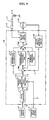
- the control unit 30 is mainly constituted by a CPU. An ordinary function to be executed by a program in the CPU is shown in FIG. 9.
- the steering torque T to be inputted after detected by the torque sensor 10 is phase-compensated by a phase-compensating device 31 for enhancing stability of a steering system and the thus-phase-compensated steering torque TA is inputted to a steering assisting command value computing device 32.
- the vehicle speed V detected by the vehicle sped sensor 12 is also inputted to the steering assisting command value computing device 32.
- the steering assisting command value computing device 32 determines the steering assisting command value I which is a control target value of the electric current to be supplied to the motor 20 based on the inputted steering torque TA and the vehicle speed V.
- the steering assisting command value I is not only inputted to a subtracting device 30A but also supplied to a differential compensating device 34 of a feed-forward system for enhancing a response speed and, then, deviation (I-i) of the subtracting device 30A is not only inputted to a proportional computing device 35 but also inputted to an integral computing device 36 of a feedback system for improving characteristics thereof.
- the output from each of the differential compensating device 34 and the integral computing device 36 is inputted to an adding device 30B in an addition manner and, then, an electric control value E which is a result of such addition in the adding device 30B is inputted to a motor drive circuit 37 as a motor drive signal.
- a motor electric current value i of the motor 20 is detected by a motor electric current detecting circuit 38 and, then, the thus-detected motor electric current value i is inputted to the subtracting device 30A, to thereby be fed back.
- FIG. 10 the mechanism as shown in FIG. 8 is shown in FIG. 10 in terms of a transfer function.
- a block 301 is a transfer function K(s) of the control unit 30
- a block 201 is a transfer function of the motor 20 which has characteristics of primary lag function
- a block 202 indicates a torque coefficient K t of the motor 20.
- a block 3A is a gear ratio G r of the reduction gear 3, and an output from the gear ratio G r and a steering torque Th are inputted to a adding device 41 and, through an subtracting device 42, inputted to a transfer function 501 of the pinion-rack mechanism 5.
- K tb spring coefficient
- FIG. 11 Frequency response characteristics of the control unit 301 is shown in FIG. 11, in which FIG. 11(A) shows gain characteristics, while FIG. 11(B) shows phase characteristics. Further, torque characteristics of the torsion bar is shown in FIG. 12(A). while the angle is shown in FIG. 12(B).
- FIG. 12 shows results of performing tuning as shown in FIG. 10 which show states of angles at the time of changing the gain of MAP 40 of the feedback signal by 1/150, 1, 10, and 50. From these results, it is found that, since there is no substantial difference among results obtained by the gains 1/150, 1, 10 and 50, it is difficult to perform tuning.
- a conventional electric power steering apparatus is configured such that it can simultaneously design stability of a system and a treatment against road surface information and disturbance information by a robust stabilization compensating device.
- the present invention has been accomplished under these circumstances and an object of the present invention is to provide an electric power steering apparatus which is easily tunable, constituted at a low cost and can obtain a safe, comfortable steering feeling.
- the present invention relates to an electric power steering apparatus which controls a motor that gives a steering assisting force to a steering mechanism based on an electric current controlling value which is computed from a steering assisting command value which has been computed by a computing device based on a steering torque generated in a steering shaft and an electric current value of the motor and the stated object of the present invention can be attained by being provided with a self-aligning torque estimating section which estimates a self-aligning torque by a disturbance observer constitution and a steering torque feedback section which performs definition of a steering reaction force based on a self-aligning torque estimated value which has been estimated by the self-aligning torque estimating section and feeds the steering reaction force back to the steering torque.
- a self-aligning torque estimating section for estimating a self-aligning torque by a disturbance observer constitution is provided and, then, definition of a steering reaction force is performed based on a self-aligning torque estimated value which has been estimated by the self-aligning torque estimating section and a motor rotation (angle) signal or angular speed signal and, thereafter, the steering reaction force is fed back to a steering torque. Further, according to the present invention, the self-aligning torque is estimated and the resultant self-aligning torque estimated value is fed back to the steering torque together with torque information of a torsion bar.
- a control unit has a robust property in that stability of a system can be secured regardless of fluctuations of characteristics (for example, resonance frequency) of the system. Still further, the definition of static characteristics of the steering reaction force is determined based on a necessary steering force and the self-aligning torque estimated value and the definition of dynamic characteristics of the steering reaction force is performed such that a gain of transfer function in a frequency band of information which is desirous to be conveyed to a driver is allowed to be large while the gain of transfer function in the frequency band of information which is not desirous to be conveyed to the driver is allowed to be small. For this account, the definition of necessary steering reaction force can easily be performed and a low-cost constitution and a stable, comfortable steering feeling can be realized.
- a motor rotation angle signal (or a motor angular speed signal) and a motor electric current command value are allowed to be used for estimating the self-aligning torque
- a constitution of the self-aligning torque estimating section of high precision and low-cost can be realized by using the motor rotation angle signal (or the motor angular speed signal) used for controlling the motor.
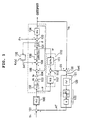
- FIG. 1 shows an example of a constitution in a block diagram according to the present invention, in which a steering torque Th is inputted in a control unit 100 (transfer function: K(s)) and, then, a motor electric current command value Ir which is an output therefrom is inputted in an adding device 105 via a motor 102 (transfer function:1/(T1 ⁇ s+1) of first order lag function, a torque function 103 (transfer function: K t ) of the motor and a gear ratio 104 (transfer function: G r ) of a reduction gear.
- a steering torque Th is inputted in a control unit 100 (transfer function: K(s)) and, then, a motor electric current command value Ir which is an output therefrom is inputted in an adding device 105 via a motor 102 (transfer function:1/(T1 ⁇ s+1) of first order lag function, a torque function 103 (transfer function: K t ) of the motor and a gear ratio 104 (transfer function:
- the addition result of the adding device 105 is inputted in a pinion-rack mechanism 130 (transfer function: 1/(J pt ⁇ s+C pt ) via a subtracting device 106.
- a motor angular speed ⁇ which is an output from the pinion-rack mechanism 130 is converted into an angle ⁇ by passing through an integral factor 131 and the thus-converted angle ⁇ is fed back to the subtracting device 106 via dynamic characteristics 132 (transfer function: Kv(s)) of a vehicle.
- the Jpt of the pinion-rack mechanism 130 is a pinion-base inertial moment, while the Cpt thereof is a pinion-base damping coefficient.
- angle ⁇ is inputted to a subtracting device 133 together with a steering wheel angle ⁇ h and, then, the subtraction result therein is inputted in an adding device 135 via a spring coefficient 134 (transfer function: K tb ) of the torsion bar, while a self-aligning torque estimated value ES is also inputted to the adding device 135 from a self-aligning torque estimating section 110.
- a spring coefficient 134 transfer function: K tb
- the self-aligning torque estimating section 110 performs an estimation of a self-aligning torque (SAT) from the motor electric current command value Ir and the motor angular speed ⁇ , and a steering torque feedback section 120 which performs a definition of a steering reaction force (complementary component) AT based on the self-aligning torque estimated value ES which has been estimated by the self-aligning torque estimating section 110 and feeds the steering reaction force back to the steering torque Th via a subtracting device 101 is provided.
- SAT self-aligning torque
- the self-aligning torque estimating section 110 comprises a factor 111 (Q/Pn) in which the motor angular speed ⁇ is inputted and treated and a factor 112 (M ⁇ Q) in which the motor electric current command value Ir is inputted and treated, is allowed to determine a deviation between the output of the factor 111 and the output of the factor 112 by a subtracting device 113 and, then, outputs the result(the deviation) as the self-aligning torque estimated value ES.
- Q(s) indicates a low-pass filter
- Pn(s) indicates a theoretical model of rack-pinion.
- the M ⁇ Q of the factor 112 is a product of an electric characteristic M of the motor and a low-pass filter Q, while the Q/Pn of the factor 111 is a quotient obtained by dividing the low-pass filter Q by an ideal model Pn.
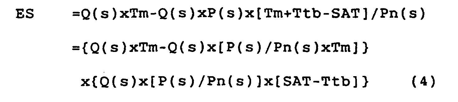
- the basis on which the self-aligning torque estimating section 110 can compute the self-aligning estimated torque value ES is as described below.
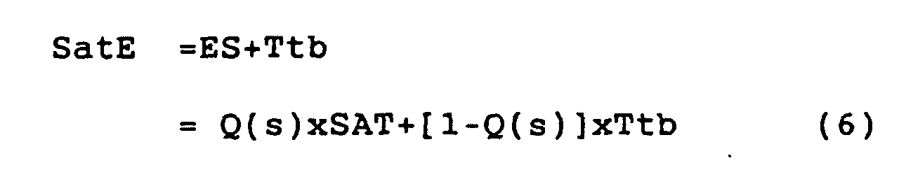
- the relation between the self-aligning torque SAT and the self-aligning torque estimated value ES is represented by the formula (5), while a relation between the self-aligning torque SAT and the addition result SatE is represented by the formula (7).
- the filter Q, the motor characteristics M and characteristics of the model Pn can be represented by respective formulae as described below.
- the Q(s) uses the angular speed ⁇ and, also, Tq is a time constant
- M(s) KtxGr/(T1 ⁇ s+1)
- P(s) 1/(Jpn ⁇ s+Cpn)
- the addition result SatE is inputted to the steering feedback section 120, while the deviation (AT-Th) between the steering torque Th and the steering reaction force AT which is an output from the steering feedback section 120 are inputted to the control unit 100 and, in the present control system, the steering torque Th and the SAT information are utilized for the feedback control.
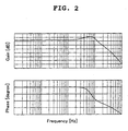
- characteristics of the control unit 100 are allowed to be gain and phase characteristics as shown in FIG. 2 without containing an integral factor and, accordingly, they become a proportional factor in a low frequency range and cutoff characteristics in a high frequency range.
- Characteristics of the self-aligning torque estimating section 110 are allowed to be those as shown in FIG. 3.
- the actual self-aligning torque SAT solid line
- the estimated self-aligning torque ES broken line
- the steering torque feedback section 120 comprises a dynamic characteristic sub-section 121 and a static characteristic sub-section 122.
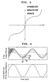
- the dynamic constituting sub-section 121 has characteristics as shown in FIG. 4, while the static characteristic sub-section 122 has characteristics as shown in FIG. 5.
- the static characteristic sub-section 122 has a function of a feeling characteristic section such that it gives a complementary effect to a torque which a driver feels and, in the present example, is separated into a function block of showing a gain g and a function block of showing a curve pattern.
- a range AR2 angular frequency from ⁇ 1 to ⁇ 2
- ranges AR1 angular frequency of ⁇ 1 or less
- AR3 angular frequency of ⁇ 2 or more
- FIG. 5 shows static characteristics to be targeted, the gain g is actually fluctuated in an appropriate range (1/150, 1, 10 and 50) so as to cover characteristics as shown in FIG. 5.
- the deviation (AT-Th) between the steering torque Th and the steering reaction force AT which is an output from the steering torque feedback section 120 is obtained by the subtracting device 101 and the deviation (AT-Th) is inputted in the control unit 100 and, then, the motor electric current command value Ir which is an output therefrom not only drives the motor 102 but also is inputted in the self-aligning torque estimating section 110 of a disturbance observer constitution.
- the control unit 100 compensates stability of an entire system and has robust characteristics by securing the stability of the entire system regardless of fluctuations of characteristics (for example, resonance frequency) of the system. Determination of the transfer function K(s) of the control unit 100 may either be performed by PID or a try-and-error method.
- An output of the motor 102 is inputted in the adding device 105 via the motor torque coefficient 103 (Kt) and the gear ratio 104 (Gr) and, then, the resultant addition value is inputted in the pinion-rack mechanism 130 (1/(Jpt ⁇ s+Cpt)) via the subtracting device 106.
- An output from the pinion-rack mechanism 130 is inputted in the subtracting device 133 via the integral factor 131 (1/s) and the output of the integral factor 131 is inputted in the factor 132 which indicates dynamic characteristics of the vehicle and, then, the self-aligning torque SAT which is an output therefrom is inputted in the subtracting device 106.
- the addition result in the subtracting device 133 is outputted via the spring coefficient 134 (Ktb) of the torsion bar.
- the steering torque feedback section 120 comprises the dynamic characteristic sub-section 121 and the static characteristic sub-section 122 of feeling characteristics of torque which a human being feels.
- the self-aligning torque for the electric power steering and the feedback control system using the steering torque are utilized and the gist thereof, that is, the control unit 100 of the feedback, being characterized by the frequency characteristics (gain and phase)in Fig.2, has no integral factor but has proportional characteristics in a low frequency range and cutoff characteristics in a high frequency range.
- the steering torque Th is measured by a torque sensor of the torsion bar, while the self-aligning torque SAT is not measured but is estimated by the self-aligning torque estimating section 110 of the observer constitution.
- the thus-estimated self-aligning torque ES and the measured self-aligning torque SAT come to be those as shown in FIG. 3.
- the result of the characteristics K(s) of the control unit 100 applied to the case of FIG. 2 come to be those as shown in FIG. 6; the feature thereof is favorable. It is found that, compared with the characteristics indicating the result of the conventional apparatus, the difference caused by the change of the gain comes to be large and, accordingly, tuning is easily performed. By contrast, when the characteristics K(s) of the control unit 100 is applied to the case of FIG. 3, the results come to be those as shown in FIG. 7; it is found that the feature thereof is unfavorable. Namely, in FIG. 7, when the gain g is changed, the torque of the torsion bar is changed but the pinion angle is largely changed and, accordingly, a following response property of the steering is deteriorated and it also becomes difficult to perform tuning.
- the angular speed ⁇ is used for the self-aligning torque estimation.
- a power steering apparatus of an automotive vehicle According to a power steering apparatus of an automotive vehicle according to the present invention, treatments of road surface information, disturbance information and the like and designing of steering stability can independently be designed, to thereby being capable of providing a low-cost constitution, easy tuning, and a stable, comfortable steering feeling.
Landscapes
- Engineering & Computer Science (AREA)
- Chemical & Material Sciences (AREA)
- Combustion & Propulsion (AREA)
- Transportation (AREA)
- Mechanical Engineering (AREA)
- Steering Control In Accordance With Driving Conditions (AREA)
- Power Steering Mechanism (AREA)
Abstract
Description
Claims (5)
- An electric power steering apparatus, which controls a motor that gives a steering assisting force to a steering mechanism based on an electric current controlling value which is computed from a steering assisting command value which has been computed by a computing device based on a steering torque generated in a steering shaft and an electric current value of the motor, being characterized by comprising a self-aligning torque estimating section which estimates a self-aligning torque by a disturbance observer constitution and a steering torque feedback section which performs definition of a steering reaction force based on a self-aligning torque estimated value which has been estimated by the self-aligning torque estimating section and feeds the steering reaction force back to the steering torque.
- The electric power steering apparatus as set forth in Claim 1, wherein definition of static characteristics of the steering torque feedback section is determined based on the steering reaction force and the self-aligning torque estimated value.
- The electric power steering apparatus as set forth in Claim 1, wherein the definition of dynamic characteristics of the steering reaction force of the steering torque feedback section is performed such that a gain of a transfer function in a frequency band of information which is desirous to be conveyed to a driver is allowed to be large, while the gain of the transfer function in the frequency band of information which is not desirous to be conveyed to the driver is allowed to be small.
- The electric power steering apparatus as set forth in Claim 1, wherein a characteristic of a controller into which a deviation between the steering torque and an output from the steering torque feedback section is inputted is allowed to be a proportional factor in a low range and a cutoff factor in a high range, without containing an integral factor.
- The electric power steering apparatus as set forth in Claim 1, wherein the self-aligning torque estimating section is allowed to estimate the self-aligning torque from a motor rotation signal or angular speed signal and a motor electric current command value.
Applications Claiming Priority (3)
| Application Number | Priority Date | Filing Date | Title |
|---|---|---|---|
| JP2002001935A JP3838101B2 (en) | 2002-01-09 | 2002-01-09 | Electric power steering device |
| JP2002001935 | 2002-01-09 | ||
| PCT/JP2003/000067 WO2003059719A1 (en) | 2002-01-09 | 2003-01-08 | Electric power steering apparatus control apparatus |
Publications (3)
| Publication Number | Publication Date |
|---|---|
| EP1470987A1 true EP1470987A1 (en) | 2004-10-27 |
| EP1470987A4 EP1470987A4 (en) | 2007-07-04 |
| EP1470987B1 EP1470987B1 (en) | 2010-03-17 |
Family
ID=19190686
Family Applications (1)
| Application Number | Title | Priority Date | Filing Date |
|---|---|---|---|
| EP03700482A Expired - Lifetime EP1470987B1 (en) | 2002-01-09 | 2003-01-08 | Electric power steering apparatus control apparatus |
Country Status (7)
| Country | Link |
|---|---|
| US (1) | US20050103561A1 (en) |
| EP (1) | EP1470987B1 (en) |
| JP (1) | JP3838101B2 (en) |
| AT (1) | ATE461095T1 (en) |
| AU (1) | AU2003201912A1 (en) |
| DE (1) | DE60331722D1 (en) |
| WO (1) | WO2003059719A1 (en) |
Cited By (4)
| Publication number | Priority date | Publication date | Assignee | Title |
|---|---|---|---|---|
| EP1679249A1 (en) * | 2005-01-11 | 2006-07-12 | Fuji Jukogyo Kabushiki Kaisha | Power steering device for a four-wheel drive vehicle |
| EP1923298A1 (en) * | 2006-11-15 | 2008-05-21 | NSK Ltd. | Electronic power steering apparatus |
| EP2050655A3 (en) * | 2007-10-15 | 2010-01-20 | Denso Corporation | Electric power steering system |
| WO2014199804A1 (en) * | 2013-06-13 | 2014-12-18 | Mitsubishi Electric Corporation | Method for controlling torque of eps system of vehicle and eps system of vehicle |
Families Citing this family (30)
| Publication number | Priority date | Publication date | Assignee | Title |
|---|---|---|---|---|
| EP1541445B1 (en) * | 2002-09-19 | 2008-04-02 | NSK Ltd., | Control device for motorized power steering device |
| US6983817B2 (en) * | 2003-03-18 | 2006-01-10 | Toyoda Koki Kabushiki Kaisha | Power steering device |
| EP1616774A3 (en) * | 2004-07-15 | 2007-08-08 | NSK Ltd., | Electric power steering apparatus |
| JP4581694B2 (en) * | 2005-01-14 | 2010-11-17 | 日本精工株式会社 | Control device for electric power steering device |
| JP4715446B2 (en) * | 2005-10-31 | 2011-07-06 | 日本精工株式会社 | Control device for electric power steering device |
| JP4545054B2 (en) * | 2005-06-29 | 2010-09-15 | 株式会社ショーワ | Electric power steering device |
| JP4545055B2 (en) * | 2005-06-29 | 2010-09-15 | 株式会社ショーワ | Electric power steering device |
| JP4627012B2 (en) * | 2005-06-29 | 2011-02-09 | 株式会社ショーワ | Electric power steering device |
| JP2007168756A (en) * | 2005-12-26 | 2007-07-05 | Showa Corp | Electric power steering device |
| JP4899541B2 (en) * | 2006-03-09 | 2012-03-21 | 日産自動車株式会社 | Vehicle steering control device |
| EP1864886A2 (en) * | 2006-06-07 | 2007-12-12 | NSK Ltd. | Electric power steering apparatus |
| JP4329792B2 (en) * | 2006-08-10 | 2009-09-09 | トヨタ自動車株式会社 | Electric power steering device |
| JP5003944B2 (en) * | 2007-04-02 | 2012-08-22 | 株式会社ジェイテクト | Vehicle steering system |
| US8938334B2 (en) * | 2007-08-10 | 2015-01-20 | Nsk Ltd. | Vehicular steering angle estimating apparatus and electric power steering apparatus mounted therewith |
| JP5194716B2 (en) * | 2007-10-30 | 2013-05-08 | 株式会社ジェイテクト | Electric power steering device |
| JP5171487B2 (en) * | 2008-09-02 | 2013-03-27 | 本田技研工業株式会社 | Steering device |
| JP4666083B2 (en) | 2009-02-12 | 2011-04-06 | 株式会社デンソー | Electric power steering device |
| US9205869B2 (en) | 2010-08-16 | 2015-12-08 | Honda Motor Co., Ltd. | System and method for determining a steering angle for a vehicle and system and method for controlling a vehicle based on same |
| JP5533822B2 (en) | 2011-09-05 | 2014-06-25 | 株式会社デンソー | Electric power steering control device |
| EP2591942B1 (en) * | 2011-11-11 | 2015-02-25 | Volvo Car Corporation | Arrangement and method for safeguarding driver attentiveness |
| WO2014050565A1 (en) * | 2012-09-25 | 2014-04-03 | 日産自動車株式会社 | Steering control device |
| CN104661895B (en) * | 2012-09-25 | 2016-07-06 | 日产自动车株式会社 | Rotary wheel control device |
| WO2014050566A1 (en) * | 2012-09-26 | 2014-04-03 | 日産自動車株式会社 | Steering control device |
| JP6252062B2 (en) * | 2013-09-17 | 2017-12-27 | 株式会社デンソー | Steering control device |
| JP6252059B2 (en) * | 2013-09-17 | 2017-12-27 | 株式会社デンソー | Steering control device |
| US10077068B2 (en) * | 2015-07-31 | 2018-09-18 | Steering Solutions Ip Holding Corporation | Inertia compensation frequency shaping for improved EPS system stability |
| CN112770960B (en) * | 2018-09-26 | 2023-10-10 | 日本电产株式会社 | Steering controls and power steering |
| JP7736562B2 (en) * | 2021-12-28 | 2025-09-09 | ニデック株式会社 | Control device, electric power steering device, and control method |
| CN118647543A (en) * | 2022-02-03 | 2024-09-13 | 株式会社捷太格特 | Steering control device and steering control method |
| CN114802425B (en) * | 2022-05-09 | 2023-07-25 | 中国第一汽车股份有限公司 | Motor output torque determining method, device, equipment and storage medium |
Family Cites Families (7)
| Publication number | Priority date | Publication date | Assignee | Title |
|---|---|---|---|---|
| JP3493806B2 (en) * | 1995-04-21 | 2004-02-03 | 日本精工株式会社 | Control device for electric power steering device |
| US6240350B1 (en) * | 1998-07-24 | 2001-05-29 | Nsk Ltd. | Control apparatus for electric power steering system |
| JP3353770B2 (en) * | 1999-08-19 | 2002-12-03 | 三菱電機株式会社 | Electric power steering controller |
| JP3696466B2 (en) * | 2000-01-31 | 2005-09-21 | 光洋精工株式会社 | Vehicle steering system |
| JP4128719B2 (en) * | 2000-02-25 | 2008-07-30 | 三菱電機株式会社 | Electric power steering control device and control method thereof |
| JP3847516B2 (en) * | 2000-03-01 | 2006-11-22 | 三菱電機株式会社 | Electric power steering control device and control method thereof |
| JP2001341658A (en) * | 2000-03-29 | 2001-12-11 | Toyoda Mach Works Ltd | Control device for electric power steering device |
-
2002
- 2002-01-09 JP JP2002001935A patent/JP3838101B2/en not_active Expired - Fee Related
-
2003
- 2003-01-08 WO PCT/JP2003/000067 patent/WO2003059719A1/en not_active Ceased
- 2003-01-08 US US10/500,890 patent/US20050103561A1/en not_active Abandoned
- 2003-01-08 EP EP03700482A patent/EP1470987B1/en not_active Expired - Lifetime
- 2003-01-08 DE DE60331722T patent/DE60331722D1/en not_active Expired - Lifetime
- 2003-01-08 AT AT03700482T patent/ATE461095T1/en not_active IP Right Cessation
- 2003-01-08 AU AU2003201912A patent/AU2003201912A1/en not_active Abandoned
Cited By (6)
| Publication number | Priority date | Publication date | Assignee | Title |
|---|---|---|---|---|
| EP1679249A1 (en) * | 2005-01-11 | 2006-07-12 | Fuji Jukogyo Kabushiki Kaisha | Power steering device for a four-wheel drive vehicle |
| EP1923298A1 (en) * | 2006-11-15 | 2008-05-21 | NSK Ltd. | Electronic power steering apparatus |
| EP2050655A3 (en) * | 2007-10-15 | 2010-01-20 | Denso Corporation | Electric power steering system |
| US8140222B2 (en) | 2007-10-15 | 2012-03-20 | Denso Corporation | Electric power steering system |
| WO2014199804A1 (en) * | 2013-06-13 | 2014-12-18 | Mitsubishi Electric Corporation | Method for controlling torque of eps system of vehicle and eps system of vehicle |
| US9037353B2 (en) | 2013-06-13 | 2015-05-19 | Mitsubishi Electric Research Laboratories, Inc. | System and method for controlling electric power steering system |
Also Published As
| Publication number | Publication date |
|---|---|
| EP1470987B1 (en) | 2010-03-17 |
| AU2003201912A1 (en) | 2003-07-30 |
| JP3838101B2 (en) | 2006-10-25 |
| EP1470987A4 (en) | 2007-07-04 |
| US20050103561A1 (en) | 2005-05-19 |
| DE60331722D1 (en) | 2010-04-29 |
| JP2003200844A (en) | 2003-07-15 |
| ATE461095T1 (en) | 2010-04-15 |
| WO2003059719A1 (en) | 2003-07-24 |
Similar Documents
| Publication | Publication Date | Title |
|---|---|---|
| EP1470987B1 (en) | Electric power steering apparatus control apparatus | |
| CN113891827B (en) | Steering device for vehicles | |
| US8818636B2 (en) | Electric power steering apparatus, control method thereof and computer readable medium | |
| US10703405B2 (en) | Steering control device | |
| EP1803627B1 (en) | Electric power steering apparatus | |
| EP2813413B1 (en) | Electric power steering system | |
| JP4670161B2 (en) | Electric power steering device for automobile | |
| EP1764284B1 (en) | Method and system for improved active damping of steering systems | |
| US5828972A (en) | Motor vehicle steering system with automatic disturbance suppression | |
| EP2942264A1 (en) | Electric power steering device | |
| US20060017413A1 (en) | Control device for motorized power steering device | |
| EP2626278B1 (en) | Electronic power steering apparatus | |
| JP4094597B2 (en) | Steering device | |
| CN113474236B (en) | Steering device for vehicles | |
| JP2009051278A (en) | Control device for electric power steering device | |
| JP4581694B2 (en) | Control device for electric power steering device | |
| EP3075636B1 (en) | Electric power steering system | |
| JP7799938B2 (en) | Motor control device | |
| JP2003170844A (en) | Control device for electric power steering device | |
| US20070162205A1 (en) | Method for steering a vehicle by means of a superimposed steering system | |
| CN118103280A (en) | Motor control device | |
| JP4409375B2 (en) | Reaction force control device | |
| CN117622308B (en) | Steering control device | |
| JP3929998B2 (en) | Reaction force control device | |
| JP3929999B2 (en) | Reaction force control device |
Legal Events
| Date | Code | Title | Description |
|---|---|---|---|
| PUAI | Public reference made under article 153(3) epc to a published international application that has entered the european phase |
Free format text: ORIGINAL CODE: 0009012 |
|
| 17P | Request for examination filed |
Effective date: 20040727 |
|
| AK | Designated contracting states |
Kind code of ref document: A1 Designated state(s): AT BE BG CH CY CZ DE DK EE ES FI FR GB GR HU IE IT LI LU MC NL PT SE SI SK TR |
|
| AX | Request for extension of the european patent |
Extension state: AL LT LV MK RO |
|
| A4 | Supplementary search report drawn up and despatched |
Effective date: 20070604 |
|
| 17Q | First examination report despatched |
Effective date: 20071002 |
|
| GRAP | Despatch of communication of intention to grant a patent |
Free format text: ORIGINAL CODE: EPIDOSNIGR1 |
|
| GRAS | Grant fee paid |
Free format text: ORIGINAL CODE: EPIDOSNIGR3 |
|
| GRAA | (expected) grant |
Free format text: ORIGINAL CODE: 0009210 |
|
| AK | Designated contracting states |
Kind code of ref document: B1 Designated state(s): AT BE BG CH CY CZ DE DK EE ES FI FR GB GR HU IE IT LI LU MC NL PT SE SI SK TR |
|
| REG | Reference to a national code |
Ref country code: GB Ref legal event code: FG4D |
|
| REG | Reference to a national code |
Ref country code: CH Ref legal event code: EP |
|
| REG | Reference to a national code |
Ref country code: IE Ref legal event code: FG4D |
|
| REF | Corresponds to: |
Ref document number: 60331722 Country of ref document: DE Date of ref document: 20100429 Kind code of ref document: P |
|
| REG | Reference to a national code |
Ref country code: NL Ref legal event code: VDEP Effective date: 20100317 |
|
| PG25 | Lapsed in a contracting state [announced via postgrant information from national office to epo] |
Ref country code: SI Free format text: LAPSE BECAUSE OF FAILURE TO SUBMIT A TRANSLATION OF THE DESCRIPTION OR TO PAY THE FEE WITHIN THE PRESCRIBED TIME-LIMIT Effective date: 20100317 Ref country code: FI Free format text: LAPSE BECAUSE OF FAILURE TO SUBMIT A TRANSLATION OF THE DESCRIPTION OR TO PAY THE FEE WITHIN THE PRESCRIBED TIME-LIMIT Effective date: 20100317 Ref country code: AT Free format text: LAPSE BECAUSE OF FAILURE TO SUBMIT A TRANSLATION OF THE DESCRIPTION OR TO PAY THE FEE WITHIN THE PRESCRIBED TIME-LIMIT Effective date: 20100317 |
|
| PG25 | Lapsed in a contracting state [announced via postgrant information from national office to epo] |
Ref country code: SE Free format text: LAPSE BECAUSE OF FAILURE TO SUBMIT A TRANSLATION OF THE DESCRIPTION OR TO PAY THE FEE WITHIN THE PRESCRIBED TIME-LIMIT Effective date: 20100317 Ref country code: NL Free format text: LAPSE BECAUSE OF FAILURE TO SUBMIT A TRANSLATION OF THE DESCRIPTION OR TO PAY THE FEE WITHIN THE PRESCRIBED TIME-LIMIT Effective date: 20100317 Ref country code: GR Free format text: LAPSE BECAUSE OF FAILURE TO SUBMIT A TRANSLATION OF THE DESCRIPTION OR TO PAY THE FEE WITHIN THE PRESCRIBED TIME-LIMIT Effective date: 20100618 Ref country code: ES Free format text: LAPSE BECAUSE OF FAILURE TO SUBMIT A TRANSLATION OF THE DESCRIPTION OR TO PAY THE FEE WITHIN THE PRESCRIBED TIME-LIMIT Effective date: 20100628 Ref country code: EE Free format text: LAPSE BECAUSE OF FAILURE TO SUBMIT A TRANSLATION OF THE DESCRIPTION OR TO PAY THE FEE WITHIN THE PRESCRIBED TIME-LIMIT Effective date: 20100317 Ref country code: CY Free format text: LAPSE BECAUSE OF FAILURE TO SUBMIT A TRANSLATION OF THE DESCRIPTION OR TO PAY THE FEE WITHIN THE PRESCRIBED TIME-LIMIT Effective date: 20100317 Ref country code: BE Free format text: LAPSE BECAUSE OF FAILURE TO SUBMIT A TRANSLATION OF THE DESCRIPTION OR TO PAY THE FEE WITHIN THE PRESCRIBED TIME-LIMIT Effective date: 20100317 |
|
| PG25 | Lapsed in a contracting state [announced via postgrant information from national office to epo] |
Ref country code: SK Free format text: LAPSE BECAUSE OF FAILURE TO SUBMIT A TRANSLATION OF THE DESCRIPTION OR TO PAY THE FEE WITHIN THE PRESCRIBED TIME-LIMIT Effective date: 20100317 Ref country code: CZ Free format text: LAPSE BECAUSE OF FAILURE TO SUBMIT A TRANSLATION OF THE DESCRIPTION OR TO PAY THE FEE WITHIN THE PRESCRIBED TIME-LIMIT Effective date: 20100317 Ref country code: BG Free format text: LAPSE BECAUSE OF FAILURE TO SUBMIT A TRANSLATION OF THE DESCRIPTION OR TO PAY THE FEE WITHIN THE PRESCRIBED TIME-LIMIT Effective date: 20100617 |
|
| PLBE | No opposition filed within time limit |
Free format text: ORIGINAL CODE: 0009261 |
|
| STAA | Information on the status of an ep patent application or granted ep patent |
Free format text: STATUS: NO OPPOSITION FILED WITHIN TIME LIMIT |
|
| PG25 | Lapsed in a contracting state [announced via postgrant information from national office to epo] |
Ref country code: PT Free format text: LAPSE BECAUSE OF FAILURE TO SUBMIT A TRANSLATION OF THE DESCRIPTION OR TO PAY THE FEE WITHIN THE PRESCRIBED TIME-LIMIT Effective date: 20100719 Ref country code: DK Free format text: LAPSE BECAUSE OF FAILURE TO SUBMIT A TRANSLATION OF THE DESCRIPTION OR TO PAY THE FEE WITHIN THE PRESCRIBED TIME-LIMIT Effective date: 20100317 |
|
| 26N | No opposition filed |
Effective date: 20101220 |
|
| PG25 | Lapsed in a contracting state [announced via postgrant information from national office to epo] |
Ref country code: IT Free format text: LAPSE BECAUSE OF FAILURE TO SUBMIT A TRANSLATION OF THE DESCRIPTION OR TO PAY THE FEE WITHIN THE PRESCRIBED TIME-LIMIT Effective date: 20100317 |
|
| PG25 | Lapsed in a contracting state [announced via postgrant information from national office to epo] |
Ref country code: MC Free format text: LAPSE BECAUSE OF NON-PAYMENT OF DUE FEES Effective date: 20110131 |
|
| REG | Reference to a national code |
Ref country code: CH Ref legal event code: PL |
|
| GBPC | Gb: european patent ceased through non-payment of renewal fee |
Effective date: 20110108 |
|
| REG | Reference to a national code |
Ref country code: IE Ref legal event code: MM4A |
|
| PG25 | Lapsed in a contracting state [announced via postgrant information from national office to epo] |
Ref country code: LI Free format text: LAPSE BECAUSE OF NON-PAYMENT OF DUE FEES Effective date: 20110131 Ref country code: CH Free format text: LAPSE BECAUSE OF NON-PAYMENT OF DUE FEES Effective date: 20110131 |
|
| PG25 | Lapsed in a contracting state [announced via postgrant information from national office to epo] |
Ref country code: GB Free format text: LAPSE BECAUSE OF NON-PAYMENT OF DUE FEES Effective date: 20110108 |
|
| PG25 | Lapsed in a contracting state [announced via postgrant information from national office to epo] |
Ref country code: IE Free format text: LAPSE BECAUSE OF NON-PAYMENT OF DUE FEES Effective date: 20110108 |
|
| PG25 | Lapsed in a contracting state [announced via postgrant information from national office to epo] |
Ref country code: LU Free format text: LAPSE BECAUSE OF NON-PAYMENT OF DUE FEES Effective date: 20110108 |
|
| PG25 | Lapsed in a contracting state [announced via postgrant information from national office to epo] |
Ref country code: TR Free format text: LAPSE BECAUSE OF FAILURE TO SUBMIT A TRANSLATION OF THE DESCRIPTION OR TO PAY THE FEE WITHIN THE PRESCRIBED TIME-LIMIT Effective date: 20100317 |
|
| PG25 | Lapsed in a contracting state [announced via postgrant information from national office to epo] |
Ref country code: HU Free format text: LAPSE BECAUSE OF FAILURE TO SUBMIT A TRANSLATION OF THE DESCRIPTION OR TO PAY THE FEE WITHIN THE PRESCRIBED TIME-LIMIT Effective date: 20100317 |
|
| REG | Reference to a national code |
Ref country code: FR Ref legal event code: PLFP Year of fee payment: 14 |
|
| REG | Reference to a national code |
Ref country code: FR Ref legal event code: PLFP Year of fee payment: 15 |
|
| REG | Reference to a national code |
Ref country code: DE Ref legal event code: R082 Ref document number: 60331722 Country of ref document: DE Representative=s name: SCHMITT-NILSON SCHRAUD WAIBEL WOHLFROM PATENTA, DE |
|
| REG | Reference to a national code |
Ref country code: FR Ref legal event code: PLFP Year of fee payment: 16 |
|
| PGFP | Annual fee paid to national office [announced via postgrant information from national office to epo] |
Ref country code: FR Payment date: 20191216 Year of fee payment: 18 |
|
| PGFP | Annual fee paid to national office [announced via postgrant information from national office to epo] |
Ref country code: DE Payment date: 20191224 Year of fee payment: 18 |
|
| REG | Reference to a national code |
Ref country code: DE Ref legal event code: R119 Ref document number: 60331722 Country of ref document: DE |
|
| PG25 | Lapsed in a contracting state [announced via postgrant information from national office to epo] |
Ref country code: FR Free format text: LAPSE BECAUSE OF NON-PAYMENT OF DUE FEES Effective date: 20210131 |
|
| PG25 | Lapsed in a contracting state [announced via postgrant information from national office to epo] |
Ref country code: DE Free format text: LAPSE BECAUSE OF NON-PAYMENT OF DUE FEES Effective date: 20210803 |