EP1470607B1 - A high-temperature fuel cell module - Google Patents
A high-temperature fuel cell module Download PDFInfo
- Publication number
- EP1470607B1 EP1470607B1 EP03731756.7A EP03731756A EP1470607B1 EP 1470607 B1 EP1470607 B1 EP 1470607B1 EP 03731756 A EP03731756 A EP 03731756A EP 1470607 B1 EP1470607 B1 EP 1470607B1
- Authority
- EP
- European Patent Office
- Prior art keywords
- layer
- fuel cell
- electrode
- layers
- solid oxide
- Prior art date
- Legal status (The legal status is an assumption and is not a legal conclusion. Google has not performed a legal analysis and makes no representation as to the accuracy of the status listed.)
- Expired - Lifetime
Links
- 239000000446 fuel Substances 0.000 title claims description 91
- 239000007787 solid Substances 0.000 claims description 60
- 239000003792 electrolyte Substances 0.000 claims description 28
- 239000000463 material Substances 0.000 claims description 20
- 239000000203 mixture Substances 0.000 claims description 11
- 230000007423 decrease Effects 0.000 claims description 9
- 230000000694 effects Effects 0.000 claims description 7
- PXHVJJICTQNCMI-UHFFFAOYSA-N Nickel Chemical compound [Ni] PXHVJJICTQNCMI-UHFFFAOYSA-N 0.000 description 8
- XEEYBQQBJWHFJM-UHFFFAOYSA-N Iron Chemical compound [Fe] XEEYBQQBJWHFJM-UHFFFAOYSA-N 0.000 description 6
- KDLHZDBZIXYQEI-UHFFFAOYSA-N Palladium Chemical compound [Pd] KDLHZDBZIXYQEI-UHFFFAOYSA-N 0.000 description 6
- BASFCYQUMIYNBI-UHFFFAOYSA-N platinum Chemical compound [Pt] BASFCYQUMIYNBI-UHFFFAOYSA-N 0.000 description 6
- BQCADISMDOOEFD-UHFFFAOYSA-N Silver Chemical compound [Ag] BQCADISMDOOEFD-UHFFFAOYSA-N 0.000 description 4
- 229910052759 nickel Inorganic materials 0.000 description 4
- 229910052709 silver Inorganic materials 0.000 description 4
- 239000004332 silver Substances 0.000 description 4
- VYZAMTAEIAYCRO-UHFFFAOYSA-N Chromium Chemical compound [Cr] VYZAMTAEIAYCRO-UHFFFAOYSA-N 0.000 description 3
- RYGMFSIKBFXOCR-UHFFFAOYSA-N Copper Chemical compound [Cu] RYGMFSIKBFXOCR-UHFFFAOYSA-N 0.000 description 3
- KJTLSVCANCCWHF-UHFFFAOYSA-N Ruthenium Chemical compound [Ru] KJTLSVCANCCWHF-UHFFFAOYSA-N 0.000 description 3
- 239000000956 alloy Substances 0.000 description 3
- 229910045601 alloy Inorganic materials 0.000 description 3
- 229910052804 chromium Inorganic materials 0.000 description 3
- 239000011651 chromium Substances 0.000 description 3
- 229910017052 cobalt Inorganic materials 0.000 description 3
- 239000010941 cobalt Substances 0.000 description 3
- GUTLYIVDDKVIGB-UHFFFAOYSA-N cobalt atom Chemical compound [Co] GUTLYIVDDKVIGB-UHFFFAOYSA-N 0.000 description 3
- 229910052802 copper Inorganic materials 0.000 description 3
- 239000010949 copper Substances 0.000 description 3
- PCHJSUWPFVWCPO-UHFFFAOYSA-N gold Chemical compound [Au] PCHJSUWPFVWCPO-UHFFFAOYSA-N 0.000 description 3
- 229910052737 gold Inorganic materials 0.000 description 3
- 239000010931 gold Substances 0.000 description 3
- 229910052742 iron Inorganic materials 0.000 description 3
- 229910052763 palladium Inorganic materials 0.000 description 3
- 229910052697 platinum Inorganic materials 0.000 description 3
- 229910052707 ruthenium Inorganic materials 0.000 description 3
- MCMNRKCIXSYSNV-UHFFFAOYSA-N Zirconium dioxide Chemical compound O=[Zr]=O MCMNRKCIXSYSNV-UHFFFAOYSA-N 0.000 description 2
- 239000011195 cermet Substances 0.000 description 2
- BQENXCOZCUHKRE-UHFFFAOYSA-N [La+3].[La+3].[O-][Mn]([O-])=O.[O-][Mn]([O-])=O.[O-][Mn]([O-])=O Chemical compound [La+3].[La+3].[O-][Mn]([O-])=O.[O-][Mn]([O-])=O.[O-][Mn]([O-])=O BQENXCOZCUHKRE-UHFFFAOYSA-N 0.000 description 1
- CETPSERCERDGAM-UHFFFAOYSA-N ceric oxide Chemical compound O=[Ce]=O CETPSERCERDGAM-UHFFFAOYSA-N 0.000 description 1
- 229910000422 cerium(IV) oxide Inorganic materials 0.000 description 1
- 229910052963 cobaltite Inorganic materials 0.000 description 1
- 239000011521 glass Substances 0.000 description 1
- 229910052746 lanthanum Inorganic materials 0.000 description 1
- FZLIPJUXYLNCLC-UHFFFAOYSA-N lanthanum atom Chemical compound [La] FZLIPJUXYLNCLC-UHFFFAOYSA-N 0.000 description 1
- 238000004519 manufacturing process Methods 0.000 description 1
- 239000005300 metallic glass Substances 0.000 description 1
- 238000000034 method Methods 0.000 description 1
- 239000007800 oxidant agent Substances 0.000 description 1
- 230000001590 oxidative effect Effects 0.000 description 1
- 239000000376 reactant Substances 0.000 description 1
- 238000007650 screen-printing Methods 0.000 description 1
Images

Classifications
-
- H—ELECTRICITY
- H01—ELECTRIC ELEMENTS
- H01M—PROCESSES OR MEANS, e.g. BATTERIES, FOR THE DIRECT CONVERSION OF CHEMICAL ENERGY INTO ELECTRICAL ENERGY
- H01M4/00—Electrodes
- H01M4/86—Inert electrodes with catalytic activity, e.g. for fuel cells
- H01M4/8605—Porous electrodes
- H01M4/8626—Porous electrodes characterised by the form
-
- H—ELECTRICITY
- H01—ELECTRIC ELEMENTS
- H01M—PROCESSES OR MEANS, e.g. BATTERIES, FOR THE DIRECT CONVERSION OF CHEMICAL ENERGY INTO ELECTRICAL ENERGY
- H01M8/00—Fuel cells; Manufacture thereof
- H01M8/02—Details
- H01M8/0202—Collectors; Separators, e.g. bipolar separators; Interconnectors
- H01M8/023—Porous and characterised by the material
- H01M8/0241—Composites
- H01M8/0245—Composites in the form of layered or coated products
-
- H—ELECTRICITY
- H01—ELECTRIC ELEMENTS
- H01M—PROCESSES OR MEANS, e.g. BATTERIES, FOR THE DIRECT CONVERSION OF CHEMICAL ENERGY INTO ELECTRICAL ENERGY
- H01M8/00—Fuel cells; Manufacture thereof
- H01M8/02—Details
- H01M8/0202—Collectors; Separators, e.g. bipolar separators; Interconnectors
- H01M8/0247—Collectors; Separators, e.g. bipolar separators; Interconnectors characterised by the form
-
- H—ELECTRICITY
- H01—ELECTRIC ELEMENTS
- H01M—PROCESSES OR MEANS, e.g. BATTERIES, FOR THE DIRECT CONVERSION OF CHEMICAL ENERGY INTO ELECTRICAL ENERGY
- H01M8/00—Fuel cells; Manufacture thereof
- H01M8/10—Fuel cells with solid electrolytes
- H01M8/12—Fuel cells with solid electrolytes operating at high temperature, e.g. with stabilised ZrO2 electrolyte
- H01M8/1231—Fuel cells with solid electrolytes operating at high temperature, e.g. with stabilised ZrO2 electrolyte with both reactants being gaseous or vaporised
-
- H—ELECTRICITY
- H01—ELECTRIC ELEMENTS
- H01M—PROCESSES OR MEANS, e.g. BATTERIES, FOR THE DIRECT CONVERSION OF CHEMICAL ENERGY INTO ELECTRICAL ENERGY
- H01M8/00—Fuel cells; Manufacture thereof
- H01M8/24—Grouping of fuel cells, e.g. stacking of fuel cells
- H01M8/241—Grouping of fuel cells, e.g. stacking of fuel cells with solid or matrix-supported electrolytes
- H01M8/2425—High-temperature cells with solid electrolytes
- H01M8/2428—Grouping by arranging unit cells on a surface of any form, e.g. planar or tubular
-
- H—ELECTRICITY
- H01—ELECTRIC ELEMENTS
- H01M—PROCESSES OR MEANS, e.g. BATTERIES, FOR THE DIRECT CONVERSION OF CHEMICAL ENERGY INTO ELECTRICAL ENERGY
- H01M8/00—Fuel cells; Manufacture thereof
- H01M8/24—Grouping of fuel cells, e.g. stacking of fuel cells
- H01M8/2465—Details of groupings of fuel cells
-
- Y—GENERAL TAGGING OF NEW TECHNOLOGICAL DEVELOPMENTS; GENERAL TAGGING OF CROSS-SECTIONAL TECHNOLOGIES SPANNING OVER SEVERAL SECTIONS OF THE IPC; TECHNICAL SUBJECTS COVERED BY FORMER USPC CROSS-REFERENCE ART COLLECTIONS [XRACs] AND DIGESTS
- Y02—TECHNOLOGIES OR APPLICATIONS FOR MITIGATION OR ADAPTATION AGAINST CLIMATE CHANGE
- Y02E—REDUCTION OF GREENHOUSE GAS [GHG] EMISSIONS, RELATED TO ENERGY GENERATION, TRANSMISSION OR DISTRIBUTION
- Y02E60/00—Enabling technologies; Technologies with a potential or indirect contribution to GHG emissions mitigation
- Y02E60/30—Hydrogen technology
- Y02E60/50—Fuel cells
Definitions
- the present invention relates to a fuel cell module, in particular to a solid oxide fuel cell module.
- Solid oxide fuel cell modules comprising a plurality of solid oxide fuel cells connected in electrical series are known.
- the solid oxide fuel cells are connected in series by interconnectors.
- Solid oxide fuel cells comprising functionally graded anode electrodes and cathode electrodes are known.
- the functionally graded anode electrodes and cathode electrodes generally comprise a first layer on the electrolyte and a second layer on the first layer.
- the first layer is arranged to optimise the electrochemical activity at the electrolyte and the second layer is arranged to provide electronic conduction perpendicular to the layers of the solid oxide fuel cells to allow current to flow from one solid oxide fuel cell to an adjacent solid oxide fuel cell via an interconnector.
- the second layers provide uniform current collection across the solid oxide fuel cells.
- WO0124300A discloses a tubular solid oxide fuel cell assembly comprising an anode layer, an anode current collector, a solid oxide electrolyte, a cathode layer and a cathode current collector.
- the anode current collector comprises a nickel mesh and the cathode current collector comprises a silver mesh.
- US4699852 discloses a tubular solid oxide fuel cell assembly comprising an anode electrode, a solid oxide electrolyte and a cathode electrode.
- the anode electrode is thicker towards an interconnector and the cathode electrode is thicker towards an interconnector.
- WO0139311A discloses a solid oxide fuel cell assembly comprising a cathode electrode, a solid oxide electrolyte and an anode electrode.
- the anode electrode is thicker towards an interconnector and the cathode electrode is thicker towards an interconnector.
- the present invention seeks to provide a novel fuel cell module.
- the present invention provides a solid oxide fuel cell module comprising a plurality of fuel cells, each fuel cell comprising a first electrode, an electrolyte and a second electrode, a plurality of interconnectors being arranged to electrically connect the fuel cells in electrical series, each interconnector electrically connecting a first electrode of one fuel cell to a second electrode of an adjacent fuel cell, the first electrode comprising a first layer on the electrolyte to optimise the electrochemical activity at the electrolyte and a second layer on the first layer to provide electronic conduction perpendicular to the layers of the fuel cell, the second layer being arranged such that electronic conduction perpendicular to the layers of the fuel cell is different at different positions in the second layer, the composition of the second layer comprises a greater proportion of a high conductivity material at a first end of the first electrode nearest the interconnector, the composition of the second layer comprises a lesser proportion of the high conductivity material at a second end of the first electrode remote from the interconnector, the proportion of high conductivity material in the second layer
- the second electrode comprising a first layer on the electrolyte to optimise the electrochemical activity at the electrolyte and a second layer on the first layer to provide electronic conduction perpendicular to the layers of the solid oxide fuel cell, the second layer being arranged such that electronic conduction perpendicular to the layers of the fuel cell is different at different positions in the second layer.
- the second layer is arranged such that at a first position near to the interconnector the electronic conduction perpendicular to the layers of the fuel cell is greater than the electronic conduction perpendicular to the layers of the fuel cell at a second position remote from the interconnector.
- the second layer is arranged such that the electronic conduction perpendicular to the layers of the fuel cell progressively decreases between the first position and the second position.
- the fuel cell module comprising a hollow support member, the fuel cells being spaced apart on at least one surface of the hollow support member.
- a prior art solid oxide fuel cell module 10 is shown in figures 1 and 2 .
- the solid oxide fuel cell module 10 comprises a hollow support member 12 and a plurality of solid oxide fuel cells 16 spaced apart longitudinally on at least one flat surface 14 of the hollow support member 12.
- the solid oxide fuel cells are electrically connected in series by a plurality of interconnectors 18.
- Each solid oxide fuel cell 16 comprises a first electrode 20, a cathode electrode, an electrolyte 22 and a second electrode 24, an anode electrode.
- the second electrode 24 is arranged on the surface 14 of the hollow support member 12, the electrolyte 22 is arranged on the second electrode 24 and the first electrode 20 is arranged on the electrolyte 22.
- the first electrode 20 and the second electrode 24 are functionally graded, as shown more clearly in figure 2 .
- the functionally graded first electrode comprises a first layer 20A on, or adjacent, the electrolyte 22 and a second layer 20B on, or adjacent, the first layer 20A.
- the functionally graded second electrode 24 comprises a first layer 24A under, or adjacent, the electrolyte 22 and a second layer 24B under, or adjacent, the first layer 24A.
- the first layers 20A, 24A are arranged to optimise the electrochemical activity at the electrolyte 22 and the second layers 20B, 24B are arranged to provide electronic conduction perpendicular to the layers 20, 22, 24 of the solid oxide fuel cells 16 to allow current to flow from one solid oxide fuel cell 16 to an adjacent solid oxide fuel cell 16 via a respective interconnector 18.
- the second layers 20B, 24B provide uniform current collection across the solid oxide fuel cells 16.
- a solid oxide fuel cell module 50 according to the present invention is shown in figures 3 , 5 and 6 .
- the solid oxide fuel cell module 50 comprises a hollow support member 32 and a plurality of solid oxide fuel cells 36 spaced apart longitudinally on at least one flat surface 34 of the hollow support member 32.
- the solid oxide fuel cells are electrically connected in series by a plurality of interconnectors 38.
- Each solid oxide fuel cell 36 comprises a first electrode 40, cathode electrode, an electrolyte 42 and a second electrode 44, anode electrode.
- the second electrode 44 is arranged on the surface 34 of the hollow support member 32, the electrolyte 42 is arranged on the second electrode 44 and the first electrode 40 is arranged on the electrolyte 42.
- the first electrode 40 and the second electrode 44 are functionally graded, as shown more clearly in figure 4 .
- the functionally graded first electrode comprises a first layer 40A on, or adjacent, the electrolyte 42 and a second layer 40B on, or adjacent, the first layer 40A.
- the functionally graded second electrode 44 comprises a first layer 44A under, or adjacent, the electrolyte 42 and a second layer 44B under, or adjacent, the first layer 44A.
- the first layers 40A, 44A are arranged to optimise the electrochemical activity at the electrolyte 42 and the second layers 40B, 44B are arranged to provide electronic conduction perpendicular to the layers 40, 42, 44 of the solid oxide fuel cells 36 to allow current to flow from one solid oxide fuel cell 36 to an adjacent solid oxide fuel cell 36 via a respective interconnector 38.
- the second layers 40B, 44B the second layer being arranged to provide differential current collection across the solid oxide fuel cells 36.
- the second layers 40B, 44B are arranged such that electronic conduction perpendicular to the layers 40, 42, 44 of the solid oxide fuel cells 16 is different at different positions in the second layers 40B, 44B.
- the second layers 40B, 44B have a different thickness at different positions such that the electronic conduction perpendicular to the layers of the solid oxide fuel cells 16 is different at different positions in the second layers 40B, 44B.
- the thickness of the second layer 40B of the first electrode 40 is greatest at a first end of the first electrode 40 nearest the interconnector 38 and the thickness of the second layer 40B of the first electrode 40 is least at the end of the first electrode 40 remote from the interconnector 18.
- the thickness of the second layer 40B gradually, continuously, decreases, or tapers, from the first end to the second end of the first electrode 40.
- the thickness of the second layer 44B of the second electrode 44 is greatest at the end of the second electrode 44 nearest the interconnector 38 and the thickness of the second layer 44B of the second electrode 44 is least at the end of the second electrode 44 remote from the interconnector 38.
- the thickness of the second layer 44B gradually, continuously, decreases, or tapers, from the first end to the second end of the second electrode 44.
- the losses associated with the second layers 40B, 44B are ohmic losses related to the current and the resistance and are simply expressed as I 2 R.
- the conductivity of the second layers 40B, 44B is related to the cross-sectional area of the second layers 40B, 44B. This arrangement reduces the amount of material used in the second layers 40B, 44B and reduces the costs of the material used in manufacturing the solid oxide fuel cells 16.
- the second layers 40B, 44B comprise at least one of palladium, platinum, silver, gold, nickel, copper, cobalt, chromium, iron or ruthenium or an alloy of two or more of these elements.
- the thickness of the second layers 40B, 44B may be 100 micrometers at the first end and 1 micrometer at the second end.
- a solid oxide fuel cell module 50 according to the present invention is shown in figure 5 .
- the solid oxide fuel cell module 50 is similar to that shown in figure 3 .
- the second layers 40B, 44B have different compositions at different positions such that the electronic conduction perpendicular to the layers of the solid oxide fuel cells 16 is different at different positions in the second layers 40B, 44B.
- the compositions of the second layers 40B, 44B are varied by varying the proportions of a high conductivity material and a low conductivity material.
- composition of the second layer 40B of the first electrode 40 comprises a greater proportion of a high conductivity material at a first end of the first electrode 40 nearest the interconnector 38 and the composition of the second layer 40B of the first electrode 40 comprises a lesser proportion of the high conductivity material at the second end of the first electrode 40 remote from the interconnector 18.
- the proportion of high conductivity material in the second layer 40B gradually, continuously, reduces from the first end to the second end of the first electrode 40.
- composition of the second layer 44B of the second electrode 44 comprises a greater proportion of the high conductivity material at a first end of the second electrode 44 nearest the interconnector 38 and the composition of the second layer 44B of the second electrode 44 comprises a lesser proportion of the high conductivity material at the second end of the second electrode 44 remote from the interconnector 38.
- the proportion of high conductivity material in the second layer 44B gradually, continuously, reduces, from the first end to the second end of the second electrode 44.
- the proportion of high conductivity material in the second layer 40B, 44B may reduce in steps rather than continuously.
- the high conductivity material comprises at least one of palladium, platinum, silver, gold, nickel, copper, cobalt, chromium, iron or ruthenium or an alloy of two or more of these elements.
- the low conductivity material comprises lanthanum manganite, lanthanum cobaltite, a cermet or an amorphous metal in a glass phase.
- the cermet comprises at least one of palladium, platinum, silver, gold, nickel, copper, cobalt, chromium, iron or ruthenium or an alloy of two or more of these elements in zirconia or ceria.
- composition at the first end of the second layers 40B, 44B is 100% high conductivity material.
- a further solid oxide fuel cell module 50 according to the present invention is shown in figures 6 and 7 .
- the solid oxide fuel cell module 50 is similar to that shown in figure 3 .
- the second layers 40B, 44B have a different geometry at different positions such that the electronic conduction perpendicular to the layers of the solid oxide fuel cells 16 is different at different positions in the second layers 40B, 44B.
- the cross-sectional area of the second layer 40B in contact with the first layer 40A is greatest at a first end of the first electrode 40 nearest the interconnector 38 and the cross-sectional area of the second layer 40B in contact with the first layer 40A is least at the end of the first electrode 40 remote from the interconnector 18.
- the cross-sectional area of the second layer 40B in contact with the first layer 40A gradually, continuously, decreases, from the first end to the second end of the first electrode 40.
- cross-sectional area of the second layer 44B in contact with the first layer 44A is greatest at the end of the second electrode 44 nearest the interconnector 38 and the cross-sectional area of the second layer 44B in contact with the first layer 44A is least at the end of the second electrode 44 remote from the interconnector 38.
- the cross-sectional area of the second layer 44B in contact with the first layer 44A gradually, continuously, decreases, from the first end to the second end of the second electrode 44.
- the second layers 40B, 44B are meshes, that is the second layers 40B, 44B comprises a plurality of holes 60 around which are lands 52.
- the number of holes per unit area remains constant but the cross-sectional area of the holes gradually increases from the first end to the second end of the second layers 40B, 44B.
- the cross-sectional area of the holes increases in steps.
- the cross-sectional area of the holes remains constant, but the number of holes gradually increases from the first end to the second end of the second layers 40B, 44B.
- These meshes are preferably produced by screenprinting, but other suitable methods may be used.
- the pitch dimension between holes is between 0.05mm and 5mm
- the diameter of the holes is between 0.05mm and 5mm
- the lands have a dimension between 0.05mm and 0.5mm.
- each of the first electrode, second electrode and electrolyte of each solid oxide fuel cell may comprise one or more layers tailored for particular properties. Seals may be provided to prevent leakage of reactants from the first electrode and second electrode of the solid oxide fuel cells.
- the present invention is applicable to these practical solid oxide fuel cell modules.
Landscapes
- Chemical & Material Sciences (AREA)
- Chemical Kinetics & Catalysis (AREA)
- Electrochemistry (AREA)
- General Chemical & Material Sciences (AREA)
- Life Sciences & Earth Sciences (AREA)
- Engineering & Computer Science (AREA)
- Manufacturing & Machinery (AREA)
- Sustainable Development (AREA)
- Sustainable Energy (AREA)
- Composite Materials (AREA)
- Fuel Cell (AREA)
Description
- The present invention relates to a fuel cell module, in particular to a solid oxide fuel cell module.
- Solid oxide fuel cell modules comprising a plurality of solid oxide fuel cells connected in electrical series are known. The solid oxide fuel cells are connected in series by interconnectors.
- Solid oxide fuel cells comprising functionally graded anode electrodes and cathode electrodes are known. The functionally graded anode electrodes and cathode electrodes generally comprise a first layer on the electrolyte and a second layer on the first layer. The first layer is arranged to optimise the electrochemical activity at the electrolyte and the second layer is arranged to provide electronic conduction perpendicular to the layers of the solid oxide fuel cells to allow current to flow from one solid oxide fuel cell to an adjacent solid oxide fuel cell via an interconnector. The second layers provide uniform current collection across the solid oxide fuel cells.
-
WO0124300A -
US4699852 discloses a tubular solid oxide fuel cell assembly comprising an anode electrode, a solid oxide electrolyte and a cathode electrode. The anode electrode is thicker towards an interconnector and the cathode electrode is thicker towards an interconnector. -
WO0139311A - Accordingly the present invention seeks to provide a novel fuel cell module.
- Accordingly the present invention provides a solid oxide fuel cell module comprising a plurality of fuel cells, each fuel cell comprising a first electrode, an electrolyte and a second electrode, a plurality of interconnectors being arranged to electrically connect the fuel cells in electrical series, each interconnector electrically connecting a first electrode of one fuel cell to a second electrode of an adjacent fuel cell, the first electrode comprising a first layer on the electrolyte to optimise the electrochemical activity at the electrolyte and a second layer on the first layer to provide electronic conduction perpendicular to the layers of the fuel cell, the second layer being arranged such that electronic conduction perpendicular to the layers of the fuel cell is different at different positions in the second layer, the composition of the second layer comprises a greater proportion of a high conductivity material at a first end of the first electrode nearest the interconnector, the composition of the second layer comprises a lesser proportion of the high conductivity material at a second end of the first electrode remote from the interconnector, the proportion of high conductivity material in the second layer continuously decreases from the first end to the second end of the first electrode or the second layer is a mesh having a plurality of holes, the number of holes per unit area remains constant, the cross-sectional area of the holes gradually increases from the first end to the second end of the second layer such that electronic conduction perpendicular to the layers of the fuel cell is different at different positions in the second layer or the second layer is a mesh having a plurality of holes, the cross-sectional area of the holes remains constant, the number of holes gradually increases from the first end to the second end of the second layer such that electronic conduction perpendicular to the layers of the fuel cell is different at different positions in the second layer.
- Preferably the second electrode comprising a first layer on the electrolyte to optimise the electrochemical activity at the electrolyte and a second layer on the first layer to provide electronic conduction perpendicular to the layers of the solid oxide fuel cell, the second layer being arranged such that electronic conduction perpendicular to the layers of the fuel cell is different at different positions in the second layer.
- Preferably the second layer is arranged such that at a first position near to the interconnector the electronic conduction perpendicular to the layers of the fuel cell is greater than the electronic conduction perpendicular to the layers of the fuel cell at a second position remote from the interconnector.
- Preferably the second layer is arranged such that the electronic conduction perpendicular to the layers of the fuel cell progressively decreases between the first position and the second position.
- Preferably the fuel cell module comprising a hollow support member, the fuel cells being spaced apart on at least one surface of the hollow support member.
- The present invention will be more fully described by way of example with reference to the accompanying drawings in which:-
-
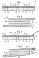
Figure 1 is a schematic cross-section through a prior art solid oxide fuel cell module. -
Figure 2 is an enlarged schematic cross-section through a single solid oxide fuel cell shown infigure 1 . -
Figure 3 is a schematic cross-section through a solid oxide fuel cell module according to the present invention. -
Figure 4 is an enlarged schematic cross-section through a single solid oxide fuel cell according to the present invention shown infigure 3 . -
Figure 5 is an enlarged schematic cross-section through a further solid oxide fuel cell according to the present invention shown infigure 3 . -
Figure 6 is an enlarged schematic cross-section through another solid oxide fuel cell according to the present invention shown infigure 3 . -
Figure 7 is a view in the direction of arrow A infigure 4 . - A prior art solid oxide
fuel cell module 10 is shown infigures 1 and 2 . The solid oxidefuel cell module 10 comprises ahollow support member 12 and a plurality of solidoxide fuel cells 16 spaced apart longitudinally on at least oneflat surface 14 of thehollow support member 12. The solid oxide fuel cells are electrically connected in series by a plurality ofinterconnectors 18. Each solidoxide fuel cell 16 comprises afirst electrode 20, a cathode electrode, anelectrolyte 22 and asecond electrode 24, an anode electrode. Thesecond electrode 24 is arranged on thesurface 14 of thehollow support member 12, theelectrolyte 22 is arranged on thesecond electrode 24 and thefirst electrode 20 is arranged on theelectrolyte 22. - The
first electrode 20 and thesecond electrode 24 are functionally graded, as shown more clearly infigure 2 . The functionally graded first electrode comprises afirst layer 20A on, or adjacent, theelectrolyte 22 and asecond layer 20B on, or adjacent, thefirst layer 20A. The functionally gradedsecond electrode 24 comprises afirst layer 24A under, or adjacent, theelectrolyte 22 and asecond layer 24B under, or adjacent, thefirst layer 24A. Thefirst layers electrolyte 22 and thesecond layers layers oxide fuel cells 16 to allow current to flow from one solidoxide fuel cell 16 to an adjacent solidoxide fuel cell 16 via arespective interconnector 18. Thesecond layers oxide fuel cells 16. - A solid oxide
fuel cell module 50 according to the present invention is shown infigures 3 ,5 and 6 . The solid oxidefuel cell module 50 comprises ahollow support member 32 and a plurality of solidoxide fuel cells 36 spaced apart longitudinally on at least oneflat surface 34 of thehollow support member 32. The solid oxide fuel cells are electrically connected in series by a plurality ofinterconnectors 38. Each solidoxide fuel cell 36 comprises afirst electrode 40, cathode electrode, anelectrolyte 42 and asecond electrode 44, anode electrode. Thesecond electrode 44 is arranged on thesurface 34 of thehollow support member 32, theelectrolyte 42 is arranged on thesecond electrode 44 and thefirst electrode 40 is arranged on theelectrolyte 42. - The
first electrode 40 and thesecond electrode 44 are functionally graded, as shown more clearly infigure 4 . The functionally graded first electrode comprises afirst layer 40A on, or adjacent, theelectrolyte 42 and asecond layer 40B on, or adjacent, thefirst layer 40A. The functionally gradedsecond electrode 44 comprises afirst layer 44A under, or adjacent, theelectrolyte 42 and asecond layer 44B under, or adjacent, thefirst layer 44A. Thefirst layers electrolyte 42 and thesecond layers layers oxide fuel cells 36 to allow current to flow from one solidoxide fuel cell 36 to an adjacent solidoxide fuel cell 36 via arespective interconnector 38. - The
second layers oxide fuel cells 36. Thesecond layers layers oxide fuel cells 16 is different at different positions in thesecond layers - In the reference example according to
figure 4 thesecond layers oxide fuel cells 16 is different at different positions in thesecond layers - In particular it is seen that the thickness of the
second layer 40B of thefirst electrode 40 is greatest at a first end of thefirst electrode 40 nearest theinterconnector 38 and the thickness of thesecond layer 40B of thefirst electrode 40 is least at the end of thefirst electrode 40 remote from theinterconnector 18. The thickness of thesecond layer 40B gradually, continuously, decreases, or tapers, from the first end to the second end of thefirst electrode 40. - Similarly the thickness of the
second layer 44B of thesecond electrode 44 is greatest at the end of thesecond electrode 44 nearest theinterconnector 38 and the thickness of thesecond layer 44B of thesecond electrode 44 is least at the end of thesecond electrode 44 remote from theinterconnector 38. The thickness of thesecond layer 44B gradually, continuously, decreases, or tapers, from the first end to the second end of thesecond electrode 44. - Alternatively it may be possible to decrease the thickness of the
second layers - The losses associated with the
second layers second layers second layers second layers oxide fuel cells 16. - The
second layers - The thickness of the
second layers - A solid oxide
fuel cell module 50 according to the present invention is shown infigure 5 . The solid oxidefuel cell module 50 is similar to that shown infigure 3 . - In this example the
second layers oxide fuel cells 16 is different at different positions in thesecond layers second layers - In particular the composition of the
second layer 40B of thefirst electrode 40 comprises a greater proportion of a high conductivity material at a first end of thefirst electrode 40 nearest theinterconnector 38 and the composition of thesecond layer 40B of thefirst electrode 40 comprises a lesser proportion of the high conductivity material at the second end of thefirst electrode 40 remote from theinterconnector 18. The proportion of high conductivity material in thesecond layer 40B gradually, continuously, reduces from the first end to the second end of thefirst electrode 40. - Similarly the composition of the
second layer 44B of thesecond electrode 44 comprises a greater proportion of the high conductivity material at a first end of thesecond electrode 44 nearest theinterconnector 38 and the composition of thesecond layer 44B of thesecond electrode 44 comprises a lesser proportion of the high conductivity material at the second end of thesecond electrode 44 remote from theinterconnector 38. The proportion of high conductivity material in thesecond layer 44B gradually, continuously, reduces, from the first end to the second end of thesecond electrode 44. - Alternatively the proportion of high conductivity material in the
second layer - It is essential to control the microstructure of the
second layers first layers first electrode 40 andsecond electrode 44. - The high conductivity material comprises at least one of palladium, platinum, silver, gold, nickel, copper, cobalt, chromium, iron or ruthenium or an alloy of two or more of these elements. The low conductivity material comprises lanthanum manganite, lanthanum cobaltite, a cermet or an amorphous metal in a glass phase. The cermet comprises at least one of palladium, platinum, silver, gold, nickel, copper, cobalt, chromium, iron or ruthenium or an alloy of two or more of these elements in zirconia or ceria.
- As an example the composition at the first end of the
second layers - A further solid oxide
fuel cell module 50 according to the present invention is shown infigures 6 and 7 . The solid oxidefuel cell module 50 is similar to that shown infigure 3 . - In this example the
second layers oxide fuel cells 16 is different at different positions in thesecond layers - In particular it is seen that the cross-sectional area of the
second layer 40B in contact with thefirst layer 40A is greatest at a first end of thefirst electrode 40 nearest theinterconnector 38 and the cross-sectional area of thesecond layer 40B in contact with thefirst layer 40A is least at the end of thefirst electrode 40 remote from theinterconnector 18. The cross-sectional area of thesecond layer 40B in contact with thefirst layer 40A gradually, continuously, decreases, from the first end to the second end of thefirst electrode 40. - Similarly the cross-sectional area of the
second layer 44B in contact with thefirst layer 44A is greatest at the end of thesecond electrode 44 nearest theinterconnector 38 and the cross-sectional area of thesecond layer 44B in contact with thefirst layer 44A is least at the end of thesecond electrode 44 remote from theinterconnector 38. The cross-sectional area of thesecond layer 44B in contact with thefirst layer 44A gradually, continuously, decreases, from the first end to the second end of thesecond electrode 44. - The second layers 40B, 44B are meshes, that is the
second layers holes 60 around which are lands 52. The number of holes per unit area remains constant but the cross-sectional area of the holes gradually increases from the first end to the second end of thesecond layers second layers - The pitch dimension between holes is between 0.05mm and 5mm, the diameter of the holes is between 0.05mm and 5mm and the lands have a dimension between 0.05mm and 0.5mm.
- The present invention has been described by way of reference to simple schematic representations of a solid oxide fuel cell module. In practice each of the first electrode, second electrode and electrolyte of each solid oxide fuel cell may comprise one or more layers tailored for particular properties. Seals may be provided to prevent leakage of reactants from the first electrode and second electrode of the solid oxide fuel cells. The present invention is applicable to these practical solid oxide fuel cell modules.
Claims (5)
- A solid oxide fuel cell module (50) comprising a plurality of solid oxide fuel cells (36), each fuel cell (36) comprising a first electrode (40), an electrolyte (42) and a second electrode (44), a plurality of interconnectors (38) being arranged to electrically connect the fuel cells (36) in electrical series, each interconnector (38) electrically connecting a first electrode (40) of one fuel cell (36) to a second electrode (44) of an adjacent fuel cell (36), the first electrode (40) comprising a first layer (40A) on the electrolyte (42) to optimise the electrochemical activity at the electrolyte (42) and a second layer (40B) on the first layer (40A) to provide electronic conduction perpendicular to the layers (40,42,44) of the fuel cell (36), the second layer (40B) being arranged such that electronic conduction perpendicular (40,42,44) to the layers of the fuel cell (36) is different at different positions in the second layer (40B) characterised in that the composition of the second layer (40B) comprises a greater proportion of a high conductivity material at a first end of the first electrode (40) nearest the interconnector (38), the composition of the second layer (40B) comprises a lesser proportion of the high conductivity material at a second end of the first electrode (40) remote from the interconnector (38), the proportion of high conductivity material in the second layer (40B) continuously decreases from the first end to the second end of the first electrode (40) or the second layer (40B) is a mesh having a plurality of holes (60), the number of holes (60) per unit area remains constant, the cross-sectional area of the holes (60) gradually increases from the first end to the second end of the second layer (40B, 44B) such that electronic conduction perpendicular to the layers (40,42,44) of the fuel cell (36) is different at different positions in the second layer (40B, 44B) or the second layer (40B) is a mesh having a plurality of holes (60), the cross-sectional area of the holes (60) remains constant, the number of holes (60) gradually increases from the first end to the second end of the second layer (40B, 44B) such that electronic conduction perpendicular to the layers of the fuel cell is different at different positions in the second layer.
- A solid oxide fuel cell module as claimed in claim 1 wherein the second electrode (44) comprising a first layer (44A) on the electrolyte (42) to optimise the electrochemical activity at the electrolyte (42) and a second layer (44B) on the first layer (44A) to provide electronic conduction perpendicular to the layers (40,42,44) of the fuel cell (36), the second layer (44B) being arranged such that electronic conduction perpendicular to the layers (40,42,44) of the fuel cell (36) is different at different positions in the second layer.
- A solid oxide fuel cell module as claimed in claim 1 or claim 2 wherein the second layer (40B, 44B) is arranged such that at a first position near to the interconnector (38) the electronic conduction perpendicular to the layers (40,42,44) of the fuel cell (36) is greater than the electronic conduction perpendicular to the layers (40,42,44) of the fuel cell (36) at a second position remote from the interconnector (38).
- A solid oxide fuel cell module as claimed in claim 3 wherein the second layer (40B, 44B) is arranged such that the electronic conduction perpendicular to the layers (40,42,44) of the fuel cell (36) progressively decreases between the first position and the second position.
- A solid oxide fuel cell module as claimed in any of claims 1 to 4 wherein the fuel cell module (50) comprising a hollow support member (32), the fuel cells (36) being spaced apart on at least one surface (34) of the hollow support member (32).
Applications Claiming Priority (3)
| Application Number | Priority Date | Filing Date | Title |
|---|---|---|---|
| GBGB0201800.0A GB0201800D0 (en) | 2002-01-26 | 2002-01-26 | A fuel cell module |
| GB0201800 | 2002-01-26 | ||
| PCT/GB2003/000272 WO2003063286A1 (en) | 2002-01-26 | 2003-01-24 | A high-temperature fuel cell module |
Publications (2)
| Publication Number | Publication Date |
|---|---|
| EP1470607A1 EP1470607A1 (en) | 2004-10-27 |
| EP1470607B1 true EP1470607B1 (en) | 2015-07-01 |
Family
ID=9929796
Family Applications (1)
| Application Number | Title | Priority Date | Filing Date |
|---|---|---|---|
| EP03731756.7A Expired - Lifetime EP1470607B1 (en) | 2002-01-26 | 2003-01-24 | A high-temperature fuel cell module |
Country Status (8)
| Country | Link |
|---|---|
| US (1) | US7473482B2 (en) |
| EP (1) | EP1470607B1 (en) |
| JP (1) | JP4191049B2 (en) |
| DK (1) | DK1470607T3 (en) |
| ES (1) | ES2542686T3 (en) |
| GB (1) | GB0201800D0 (en) |
| RU (1) | RU2303839C2 (en) |
| WO (1) | WO2003063286A1 (en) |
Families Citing this family (20)
| Publication number | Priority date | Publication date | Assignee | Title |
|---|---|---|---|---|
| JP2005276670A (en) | 2004-03-25 | 2005-10-06 | Toyota Motor Corp | Fuel cell stack |
| JP2006019044A (en) * | 2004-06-30 | 2006-01-19 | Dainippon Printing Co Ltd | Solid oxide fuel cell |
| JP4609732B2 (en) * | 2004-07-22 | 2011-01-12 | トヨタ自動車株式会社 | Current collector plate, fuel cell, and manufacturing method thereof |
| US7588856B2 (en) * | 2004-08-04 | 2009-09-15 | Corning Incorporated | Resistive-varying electrode structure |
| JP4658626B2 (en) * | 2005-01-26 | 2011-03-23 | 京セラ株式会社 | End current collecting member, fuel cell stack using the same, and fuel cell |
| US7804172B2 (en) * | 2006-01-10 | 2010-09-28 | Halliburton Energy Services, Inc. | Electrical connections made with dissimilar metals |
| GB2440038B (en) * | 2006-07-07 | 2009-04-15 | Ceres Ip Co Ltd | Metal substrate for fuel cells |
| JP5192702B2 (en) * | 2007-01-31 | 2013-05-08 | 京セラ株式会社 | Horizontally-striped fuel cell, cell stack, and fuel cell |
| US9178244B2 (en) | 2009-12-28 | 2015-11-03 | Intelligent Energy Limited | Fuel cells and fuel cell components having asymmetric architecture and methods thereof |
| US8785077B2 (en) * | 2009-12-28 | 2014-07-22 | Societe Bic | Apparatus and methods for connecting fuel cells to an external circuit |
| US9397351B2 (en) | 2009-12-28 | 2016-07-19 | Intelligent Energy Limited | Apparatus and methods for connecting fuel cells to an external circuit |
| US9281527B2 (en) | 2011-06-15 | 2016-03-08 | Lg Fuel Cell Systems Inc. | Fuel cell system with interconnect |
| US9531013B2 (en) | 2011-06-15 | 2016-12-27 | Lg Fuel Cell Systems Inc. | Fuel cell system with interconnect |
| US9147888B2 (en) * | 2011-06-15 | 2015-09-29 | Lg Fuel Cell Systems Inc. | Fuel cell system with interconnect |
| US9525181B2 (en) | 2011-06-15 | 2016-12-20 | Lg Fuel Cell Systems Inc. | Fuel cell system with interconnect |
| AU2014227989A1 (en) | 2013-03-15 | 2015-10-08 | Lg Fuel Cell Systems, Inc. | Fuel cell system configured to capture chromium |
| DE102014202337A1 (en) | 2014-02-10 | 2015-08-13 | Robert Bosch Gmbh | Housing with improved heat conduction |
| US10003083B2 (en) | 2014-07-21 | 2018-06-19 | Lg Fuel Cell Systems, Inc. | Composition for fuel cell electrode |
| US10115973B2 (en) | 2015-10-28 | 2018-10-30 | Lg Fuel Cell Systems Inc. | Composition of a nickelate composite cathode for a fuel cell |
| EP4152446A1 (en) * | 2021-09-17 | 2023-03-22 | Airbus SAS | Fuel cell with increased gravimetric power density |
Family Cites Families (10)
| Publication number | Priority date | Publication date | Assignee | Title |
|---|---|---|---|---|
| JPH081811B2 (en) * | 1985-08-22 | 1996-01-10 | 三菱重工業株式会社 | Electrode element structure |
| JPH01258365A (en) * | 1988-04-06 | 1989-10-16 | Hitachi Ltd | Fuel cell |
| JP2528989B2 (en) * | 1990-02-15 | 1996-08-28 | 日本碍子株式会社 | Solid oxide fuel cell |
| RU2045796C1 (en) * | 1993-02-03 | 1995-10-10 | Инновационное предприятие "Новатех-патент" | Electrochemical device with solid electrolyte and method of its operation |
| DE19502391C1 (en) * | 1995-01-26 | 1996-05-23 | Fraunhofer Ges Forschung | Membrane electrode unit formed by combining flat single cells and their use |
| JP3478080B2 (en) * | 1997-09-16 | 2003-12-10 | 株式会社村田製作所 | Method for manufacturing solid oxide fuel cell |
| RU2128384C1 (en) * | 1997-10-07 | 1999-03-27 | Государственный научный центр Российской Федерации - Физико-энергетический институт им.акад.А.И.Лейпунского | Solid-oxide fuel cell and its manufacturing process |
| RU2138885C1 (en) * | 1997-11-05 | 1999-09-27 | Миллер Олег Олегович | Unit of assemblies of solid oxide fuel elements with coefficient of thermal expansion exceeding that of their electrolyte |
| AUPQ315499A0 (en) * | 1999-09-29 | 1999-10-21 | Ceramic Fuel Cells Limited | Fuel cell assembly |
| US6361893B1 (en) | 1999-11-26 | 2002-03-26 | The United States Of America As Represented By The Department Of Energy | Planar fuel cell utilizing nail current collectors for increased active surface area |
-
2002
- 2002-01-26 GB GBGB0201800.0A patent/GB0201800D0/en not_active Ceased
-
2003
- 2003-01-24 JP JP2003563037A patent/JP4191049B2/en not_active Expired - Fee Related
- 2003-01-24 DK DK03731756.7T patent/DK1470607T3/en active
- 2003-01-24 EP EP03731756.7A patent/EP1470607B1/en not_active Expired - Lifetime
- 2003-01-24 RU RU2004122636/09A patent/RU2303839C2/en not_active IP Right Cessation
- 2003-01-24 ES ES03731756.7T patent/ES2542686T3/en not_active Expired - Lifetime
- 2003-01-24 WO PCT/GB2003/000272 patent/WO2003063286A1/en not_active Ceased
-
2004
- 2004-07-23 US US10/897,106 patent/US7473482B2/en not_active Expired - Fee Related
Also Published As
| Publication number | Publication date |
|---|---|
| GB0201800D0 (en) | 2002-03-13 |
| WO2003063286A1 (en) | 2003-07-31 |
| RU2303839C2 (en) | 2007-07-27 |
| DK1470607T3 (en) | 2015-07-20 |
| US20050014049A1 (en) | 2005-01-20 |
| US7473482B2 (en) | 2009-01-06 |
| JP2005516353A (en) | 2005-06-02 |
| ES2542686T3 (en) | 2015-08-10 |
| JP4191049B2 (en) | 2008-12-03 |
| EP1470607A1 (en) | 2004-10-27 |
| RU2004122636A (en) | 2005-07-10 |
Similar Documents
| Publication | Publication Date | Title |
|---|---|---|
| US7473482B2 (en) | Fuel cell module | |
| US5064734A (en) | Current-transmitting components for stacked high-temperature fuel cells and method of producing them | |
| US6444340B1 (en) | Electrical conductivity in a fuel cell assembly | |
| US20050136312A1 (en) | Compliant fuel cell system | |
| US7588856B2 (en) | Resistive-varying electrode structure | |
| DE69102669T2 (en) | Solid oxide fuel cells. | |
| US7074513B2 (en) | Unit cell for solid electrolyte type fuel cell and related manufacturing method | |
| US20020048700A1 (en) | Internally manifolded, planar solid oxide fuel cell (SOFC) stack with an inexpensive interconnect | |
| US8389180B2 (en) | Electrolytic/fuel cell bundles and systems including a current collector in communication with an electrode thereof | |
| KR20160132387A (en) | Porous current collector, fuel cell and method for producing porous current collector | |
| JP5592789B2 (en) | Cell material variations in SOFC stacks addressing thermal gradients in all planes | |
| EP1727228A1 (en) | Monopolar membrane-electrode assembly | |
| JPH03171562A (en) | Element arrangement for current conduction of ceramic high-temperature fuel cell | |
| WO2007093759A1 (en) | A solid oxide fuel cell module with multilayered anode | |
| US7575821B2 (en) | Interconnect supported fuel cell assembly and preform | |
| EP1472754A1 (en) | High temperature fuel cell module with size-reduced interconnectors | |
| US20110294041A1 (en) | Solid oxide fuel cell with special cell geometry | |
| EP4459724A1 (en) | Method for manufacturing tubular solid oxide fuel cells and battery | |
| CA2621418A1 (en) | Fuel cell and method for manufacturing same | |
| US20040033408A1 (en) | Selective coatings for PEM fuel cell electrode contacts | |
| US9005845B2 (en) | Solid oxide fuel cell and manufacturing method thereof | |
| US8951691B2 (en) | Solid oxide fuel cell stack | |
| US20190157705A1 (en) | Multiple fuel cell secondary interconnect bonding pads and wires |
Legal Events
| Date | Code | Title | Description |
|---|---|---|---|
| PUAI | Public reference made under article 153(3) epc to a published international application that has entered the european phase |
Free format text: ORIGINAL CODE: 0009012 |
|
| 17P | Request for examination filed |
Effective date: 20040826 |
|
| AK | Designated contracting states |
Kind code of ref document: A1 Designated state(s): AT BE BG CH CY CZ DE DK EE ES FI FR GB GR HU IE IT LI LU MC NL PT SE SI SK TR |
|
| AX | Request for extension of the european patent |
Extension state: AL LT LV MK RO |
|
| RAP1 | Party data changed (applicant data changed or rights of an application transferred) |
Owner name: ROLLS-ROYCE FUEL CELL SYSTEMS LIMITED |
|
| RAP1 | Party data changed (applicant data changed or rights of an application transferred) |
Owner name: LG FUEL CELL SYSTEMS, INC. |
|
| GRAP | Despatch of communication of intention to grant a patent |
Free format text: ORIGINAL CODE: EPIDOSNIGR1 |
|
| INTG | Intention to grant announced |
Effective date: 20150305 |
|
| GRAS | Grant fee paid |
Free format text: ORIGINAL CODE: EPIDOSNIGR3 |
|
| GRAA | (expected) grant |
Free format text: ORIGINAL CODE: 0009210 |
|
| AK | Designated contracting states |
Kind code of ref document: B1 Designated state(s): AT BE BG CH CY CZ DE DK EE ES FI FR GB GR HU IE IT LI LU MC NL PT SE SI SK TR |
|
| REG | Reference to a national code |
Ref country code: GB Ref legal event code: FG4D |
|
| REG | Reference to a national code |
Ref country code: AT Ref legal event code: REF Ref document number: 734447 Country of ref document: AT Kind code of ref document: T Effective date: 20150715 Ref country code: CH Ref legal event code: EP |
|
| REG | Reference to a national code |
Ref country code: DK Ref legal event code: T3 Effective date: 20150713 |
|
| REG | Reference to a national code |
Ref country code: ES Ref legal event code: FG2A Ref document number: 2542686 Country of ref document: ES Kind code of ref document: T3 Effective date: 20150810 |
|
| REG | Reference to a national code |
Ref country code: IE Ref legal event code: FG4D |
|
| REG | Reference to a national code |
Ref country code: DE Ref legal event code: R096 Ref document number: 60347758 Country of ref document: DE |
|
| REG | Reference to a national code |
Ref country code: CH Ref legal event code: NV Representative=s name: MICHELI AND CIE SA, CH |
|
| REG | Reference to a national code |
Ref country code: AT Ref legal event code: MK05 Ref document number: 734447 Country of ref document: AT Kind code of ref document: T Effective date: 20150701 |
|
| REG | Reference to a national code |
Ref country code: FR Ref legal event code: PLFP Year of fee payment: 14 |
|
| PG25 | Lapsed in a contracting state [announced via postgrant information from national office to epo] |
Ref country code: FI Free format text: LAPSE BECAUSE OF FAILURE TO SUBMIT A TRANSLATION OF THE DESCRIPTION OR TO PAY THE FEE WITHIN THE PRESCRIBED TIME-LIMIT Effective date: 20150701 Ref country code: GR Free format text: LAPSE BECAUSE OF FAILURE TO SUBMIT A TRANSLATION OF THE DESCRIPTION OR TO PAY THE FEE WITHIN THE PRESCRIBED TIME-LIMIT Effective date: 20151002 |
|
| PG25 | Lapsed in a contracting state [announced via postgrant information from national office to epo] |
Ref country code: AT Free format text: LAPSE BECAUSE OF FAILURE TO SUBMIT A TRANSLATION OF THE DESCRIPTION OR TO PAY THE FEE WITHIN THE PRESCRIBED TIME-LIMIT Effective date: 20150701 Ref country code: PT Free format text: LAPSE BECAUSE OF FAILURE TO SUBMIT A TRANSLATION OF THE DESCRIPTION OR TO PAY THE FEE WITHIN THE PRESCRIBED TIME-LIMIT Effective date: 20151102 Ref country code: SE Free format text: LAPSE BECAUSE OF FAILURE TO SUBMIT A TRANSLATION OF THE DESCRIPTION OR TO PAY THE FEE WITHIN THE PRESCRIBED TIME-LIMIT Effective date: 20150701 |
|
| REG | Reference to a national code |
Ref country code: DE Ref legal event code: R097 Ref document number: 60347758 Country of ref document: DE |
|
| PG25 | Lapsed in a contracting state [announced via postgrant information from national office to epo] |
Ref country code: EE Free format text: LAPSE BECAUSE OF FAILURE TO SUBMIT A TRANSLATION OF THE DESCRIPTION OR TO PAY THE FEE WITHIN THE PRESCRIBED TIME-LIMIT Effective date: 20150701 Ref country code: SK Free format text: LAPSE BECAUSE OF FAILURE TO SUBMIT A TRANSLATION OF THE DESCRIPTION OR TO PAY THE FEE WITHIN THE PRESCRIBED TIME-LIMIT Effective date: 20150701 Ref country code: CZ Free format text: LAPSE BECAUSE OF FAILURE TO SUBMIT A TRANSLATION OF THE DESCRIPTION OR TO PAY THE FEE WITHIN THE PRESCRIBED TIME-LIMIT Effective date: 20150701 |
|
| PLBE | No opposition filed within time limit |
Free format text: ORIGINAL CODE: 0009261 |
|
| STAA | Information on the status of an ep patent application or granted ep patent |
Free format text: STATUS: NO OPPOSITION FILED WITHIN TIME LIMIT |
|
| REG | Reference to a national code |
Ref country code: DE Ref legal event code: R082 Ref document number: 60347758 Country of ref document: DE Representative=s name: HERNANDEZ, YORCK, DIPL.-ING., DE |
|
| 26N | No opposition filed |
Effective date: 20160404 |
|
| PG25 | Lapsed in a contracting state [announced via postgrant information from national office to epo] |
Ref country code: SI Free format text: LAPSE BECAUSE OF FAILURE TO SUBMIT A TRANSLATION OF THE DESCRIPTION OR TO PAY THE FEE WITHIN THE PRESCRIBED TIME-LIMIT Effective date: 20150701 Ref country code: LU Free format text: LAPSE BECAUSE OF FAILURE TO SUBMIT A TRANSLATION OF THE DESCRIPTION OR TO PAY THE FEE WITHIN THE PRESCRIBED TIME-LIMIT Effective date: 20160124 |
|
| PG25 | Lapsed in a contracting state [announced via postgrant information from national office to epo] |
Ref country code: MC Free format text: LAPSE BECAUSE OF FAILURE TO SUBMIT A TRANSLATION OF THE DESCRIPTION OR TO PAY THE FEE WITHIN THE PRESCRIBED TIME-LIMIT Effective date: 20150701 |
|
| REG | Reference to a national code |
Ref country code: IE Ref legal event code: MM4A |
|
| REG | Reference to a national code |
Ref country code: FR Ref legal event code: PLFP Year of fee payment: 15 |
|
| PG25 | Lapsed in a contracting state [announced via postgrant information from national office to epo] |
Ref country code: IE Free format text: LAPSE BECAUSE OF NON-PAYMENT OF DUE FEES Effective date: 20160124 |
|
| PGFP | Annual fee paid to national office [announced via postgrant information from national office to epo] |
Ref country code: NL Payment date: 20170119 Year of fee payment: 15 |
|
| PGFP | Annual fee paid to national office [announced via postgrant information from national office to epo] |
Ref country code: CH Payment date: 20170119 Year of fee payment: 15 Ref country code: DE Payment date: 20170120 Year of fee payment: 15 Ref country code: FR Payment date: 20170120 Year of fee payment: 15 |
|
| PGFP | Annual fee paid to national office [announced via postgrant information from national office to epo] |
Ref country code: BE Payment date: 20170119 Year of fee payment: 15 Ref country code: DK Payment date: 20170119 Year of fee payment: 15 Ref country code: GB Payment date: 20170119 Year of fee payment: 15 |
|
| PGFP | Annual fee paid to national office [announced via postgrant information from national office to epo] |
Ref country code: ES Payment date: 20170113 Year of fee payment: 15 Ref country code: IT Payment date: 20170124 Year of fee payment: 15 Ref country code: TR Payment date: 20170116 Year of fee payment: 15 |
|
| PG25 | Lapsed in a contracting state [announced via postgrant information from national office to epo] |
Ref country code: CY Free format text: LAPSE BECAUSE OF FAILURE TO SUBMIT A TRANSLATION OF THE DESCRIPTION OR TO PAY THE FEE WITHIN THE PRESCRIBED TIME-LIMIT Effective date: 20150701 Ref country code: HU Free format text: LAPSE BECAUSE OF FAILURE TO SUBMIT A TRANSLATION OF THE DESCRIPTION OR TO PAY THE FEE WITHIN THE PRESCRIBED TIME-LIMIT; INVALID AB INITIO Effective date: 20030124 |
|
| PG25 | Lapsed in a contracting state [announced via postgrant information from national office to epo] |
Ref country code: BG Free format text: LAPSE BECAUSE OF FAILURE TO SUBMIT A TRANSLATION OF THE DESCRIPTION OR TO PAY THE FEE WITHIN THE PRESCRIBED TIME-LIMIT Effective date: 20150701 |
|
| REG | Reference to a national code |
Ref country code: DE Ref legal event code: R119 Ref document number: 60347758 Country of ref document: DE |
|
| REG | Reference to a national code |
Ref country code: DK Ref legal event code: EBP Effective date: 20180131 |
|
| REG | Reference to a national code |
Ref country code: CH Ref legal event code: PL |
|
| REG | Reference to a national code |
Ref country code: NL Ref legal event code: MM Effective date: 20180201 |
|
| GBPC | Gb: european patent ceased through non-payment of renewal fee |
Effective date: 20180124 |
|
| PG25 | Lapsed in a contracting state [announced via postgrant information from national office to epo] |
Ref country code: FR Free format text: LAPSE BECAUSE OF NON-PAYMENT OF DUE FEES Effective date: 20180131 Ref country code: DE Free format text: LAPSE BECAUSE OF NON-PAYMENT OF DUE FEES Effective date: 20180801 |
|
| REG | Reference to a national code |
Ref country code: FR Ref legal event code: ST Effective date: 20180928 |
|
| REG | Reference to a national code |
Ref country code: BE Ref legal event code: FP Effective date: 20150716 Ref country code: BE Ref legal event code: MM Effective date: 20180131 |
|
| PG25 | Lapsed in a contracting state [announced via postgrant information from national office to epo] |
Ref country code: LI Free format text: LAPSE BECAUSE OF NON-PAYMENT OF DUE FEES Effective date: 20180131 Ref country code: CH Free format text: LAPSE BECAUSE OF NON-PAYMENT OF DUE FEES Effective date: 20180131 Ref country code: NL Free format text: LAPSE BECAUSE OF NON-PAYMENT OF DUE FEES Effective date: 20180201 Ref country code: GB Free format text: LAPSE BECAUSE OF NON-PAYMENT OF DUE FEES Effective date: 20180124 Ref country code: BE Free format text: LAPSE BECAUSE OF NON-PAYMENT OF DUE FEES Effective date: 20180131 |
|
| PG25 | Lapsed in a contracting state [announced via postgrant information from national office to epo] |
Ref country code: DK Free format text: LAPSE BECAUSE OF NON-PAYMENT OF DUE FEES Effective date: 20180131 |
|
| PG25 | Lapsed in a contracting state [announced via postgrant information from national office to epo] |
Ref country code: IT Free format text: LAPSE BECAUSE OF NON-PAYMENT OF DUE FEES Effective date: 20180124 |
|
| REG | Reference to a national code |
Ref country code: ES Ref legal event code: FD2A Effective date: 20190731 |
|
| PG25 | Lapsed in a contracting state [announced via postgrant information from national office to epo] |
Ref country code: ES Free format text: LAPSE BECAUSE OF NON-PAYMENT OF DUE FEES Effective date: 20180125 |
|
| PG25 | Lapsed in a contracting state [announced via postgrant information from national office to epo] |
Ref country code: TR Free format text: LAPSE BECAUSE OF NON-PAYMENT OF DUE FEES Effective date: 20180124 |