CROSS-REFERENCE TO RELATED APPLICATIONS/INCORPORATION BY REFERENCE
This application makes reference to, claims priority to, and claims the benefit of:
The above stated applications are incorporated herein by reference in their
entirety.
FIELD OF THE INVENTION
Certain embodiments of the invention relate to encoding of information. More
specifically, certain embodiments of the invention relate to a method and system for
providing synchronous running encoding and encryption and corresponding decoding
and decryption in a communication channel or link.
BACKGROUND OF THE INVENTION
Serial data communication between two link partners in a digital communication
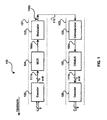
system may be accomplished according to the general configuration of FIG. 1. FIG. 1 is
a block diagram illustrating a conventional digital communication link 100 having a
transmitter side 101 and a receiver side 102. The transmitter side 101 may include an
encoder 103, a multiplexer (MUX) 104, and a modulator 105. The receiver side 102
may include a demodulator 106, a demultiplexer (DEMUX) 107, and a decoder 108.
The transmitter side 101 and the receiver side 102 may be coupled by a link
infrastructure 110. Alternatively, the link infrastructure may be a loopback path.
Notwithstanding, the link infrastructure 110 may be, for example, shielded twisted pair,
unshielded twisted pair (UTP), copper wire, or optical fiber.
Typically, the encoder 103 may be adapted to accept raw data bytes from an
upstream component or entity of the digital communication system. The raw data bytes
may be 8-bit words and may have been previously encrypted by an upstream
component or entity of a digital communication system or the communication link 100.
Prior encryption of the 8-bit words may ensure data integrity while the encrypted data
traverses the digital communication link 100. Notwithstanding, the coded words may be
coded in a manner specially designed to provide reliable transmission over the digital
communication link 100.
The encoder 103 may encode each of the 8-bit words into a coded word having n
bits. Generally, n is greater than eight (8) bits (n>8). Encoding the 8-bit words may
generally be achieved by translating each 8-bit byte of data into a specially coded word
having n bits where n is generally greater than eight (8). For example, for Gigabit
Ethernet encoding, n is equal to ten (10). The additional (n-8) bits of data provide
additional transmission overhead. The increased number of bits resulting from
encoding may also provide data redundancy which is typically utilized for error
detection. In addition to the encoding of data words, the additional bits may also be
encoded to form control words. Standardized coding such as 3B4B, 5B6B or 8B10B
coding are typically utilized to ensure data integrity and transmission reliability.
Once the raw data bytes have been encoded by the encoder 103, the resulting
coded data 111a may be multiplexed into a serial bitstream 109a by the multiplexer 104.
The resulting multiplexed serial bitstream 109a may subsequently be transferred to the
modulator 105 for processing. The modulator 105 may perform digital-to-analog
conversion on the serial bitstream 109a, resulting in an equivalent or corresponding
bitstream 109b. The resulting analog serial bitstream 109b may be transferred to the
receiver side 102 via the link infrastructure or loopback 110.
The demodulator 106 on the receiver side 102 may be adapted to receive the
analog serial bitstream 109b transferred from the transmitter side 101. The
demodulator 106 may perform an analog-to-digital conversion on the received serial
bitstream 109b, resulting in a serial digital bitstream 109c. The resulting serial digital
bitstream 109c generated by the demodulator 106 may be transferred to the
demultiplexer 107 for processing. The demultiplexer 107 may be configured to
demultiplex the serial digital bitstream 109c by executing the opposite of the
multiplexing function performed by multiplexer 104.
The demultiplexer 107 may translate the serial bitstream 109c back into a
datastream 111b containing n-bit coded words. For example, in the case of gigabit
Ethernet, the demultiplexer 107 may translate the serial bitstream 109c back into 10-bit
coded words. The n-bit coded words produced by the demultiplexer 107 may
subsequently be transferred to the decoder 108 for processing. The decoder 108 may
be adapted to execute the opposite of the encoder function performed by the encoder
103. In this regard, the decoder 108 may convert the n-bit coded words back into 8-bit
unencoded bytes. These 8-bit unencoded bytes, if previously encrypted, may be
decrypted by an upstream component of the digital communication link 100, for
example.
Some coding schemes such as 3B4B, 5B6B and 8B10B encoding, utilize a
concept referred to as running disparity (RD). Running disparity refers to the sign,
whether positive (+) or negative (-), of a running digital sum (RDS) value. The running
digital sum value may represent the running sum of the encoded bits used to represent
unencoded data. Typically, logic one (1) may be represented by a positive one (+1)
and a logic zero (0) may be represented by a negative one (-1). The running disparity
and running digital sum are used in encoding to minimize the DC component of the
transmitted coded words on the digital communication link 100.
For example, the 8B10B code is an encoding scheme that translates 8-bit bytes
into 10-bit coded words using the running disparity. Some of the features provided by
the 8B10B coding scheme may include DC balance, a maximum run length of 5, a
maximum RDS of 3, a transition density of 3 to 8 transitions per 10-bit code group,
separate code groups for control signaling, and a comma for synchronization of code
groups. Below is a standardized 8B10B table that illustrates exemplary data code
groups and their corresponding RD(-) and RD(+) translations. The first column of the
table, referred to as the code group name, contains data values to be encoded. The
second column of the table represents corresponding octal values for the data values to
be encoded. The third column of the table represents corresponding byte bits values for
the data values to be encoded. The fourth column represents the corresponding
encoded (RD-) values for the data values that were to be encoded. Finally, the fifth
column represents the encoded (RD+) values for the data values that were to be
encoded.
| Code-Group Name | Byte Value | Byte Bits
HGF EDCBA | RD (-)
abcdei fghj | RD (+)
abcdei fghj |
| D0.0 | 00 | 000 00000 | 100111 0100 | 011000 1011 |
| D1.0 | 01 | 000 00001 | 011101 0100 | 100010 1011 |
| D2.0 | 02 | 000 00010 | 101101 0100 | 010010 1011 |
| ... | ... | ... | ... | ... |
| D0.1 | 20 | 001 00000 | 100111 1001 | 011000 1001 |
| D1.1 | 21 | 001 00001 | 011101 1001 | 100010 1001 |
| D2.1 | 22 | 011 00010 | 101101 1001 | 010010 1001 |
| ... | ... | ... | ... | ... |
| D0.2 | 40 | 010 00000 | 100111 0101 | 011000 0101 |
| D1.2 | 41 | 010 00001 | 011101 0101 | 100010 0101 |
| D2.2 | 42 | 010 00010 | 101101 0101 | 010010 0101 |
| ... | ... | ... | ... | ... |
| D0.3 | 60 | 011 00000 | 100111 0011 | 011000 1100 |
| D1.3 | 61 | 011 00001 | 011101 0011 | 100010 1100 |
| D2.3 | 62 | 011 00010 | 101101 0011 | 010010 1100 |
| ... | ... | ... | ... | ... |
| D0.4 | 80 | 100 00000 | 100111 0010 | 011000 1101 |
| D1.4 | 81 | 100 00001 | 011101 0010 | 100010 1101 |
| D2.4 | 82 | 100 00010 | 101101 0010 | 010010 1101 |
| ... | ... | ... | ... | ... |
| D0.5 | A0 | 101 00000 | 1001111010 | 011000 1010 |
| D1.5 | A1 | 101 00001 | 011101 1010 | 100010 1010 |
| D2.5 | A2 | 101 00010 | 101101 1010 | 010010 1010 |
| ... | ... | ... | ... | ... |
| D0.6 | C0 | 110 00000 | 100111 0110 | 011000 0110 |
| D1.6 | C1 | 110 00001 | 011101 0110 | 100010 0110 |
| D2.6 | C2 | 110 00010 | 101101 0110 | 010010 0110 |
| ... | ... | ... | ... | ... |
| D0.7 | E0 | 111 00000 | 100111 0001 | 011000 1110 |
| D1.7 | E1 | 111 00001 | 011101 0001 | 100010 1110 |
| D2.7 | E2 | 111 00010 | 101101 0001 | 010010 1110 |
| ... | ... | ... | ... | ... |
| D31.7 | FF | 111 11111 | 101011 0001 | 010100 1110 |
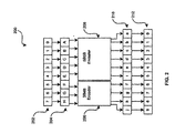
FIG. 2 is an encoder system 200 that may be utilized for generating standardized
8B/10B encoding as illustrated in the table above. Referring to FIG. 2, the encoder
system 200 may include an input byte bit block 202, an input byte bit label block 204, a
3B4B encoder block 206, a 4B5B encoder block 208, an output code-group bit label
block 210 and an encoded output code-group block 212. Input byte bit label block 204
illustrates the arrangement or mapping of the input byte bits corresponding to the input
byte bit block 202. Accordingly, input bit 0 corresponds to A, input bit 1 corresponds to
B, input bit 2 corresponds to C, input bit 3 corresponds to D, input bit 4 corresponds to
E, input bit 5 corresponds to F, input bit 6 corresponds to G, and input bit 7 corresponds
to H.
Input byte bits A, B, C, D and E are routed to the input of the 5B6B encoder bock
208 and input byte bits F, G and H are routed to the input of the 3B4B encoder block
206. The output encoded bits generated by the encoder block 208 includes output code
group bits a, b, c d, e and i. The output encoded bits generated by the encoder block
206 includes output code group bits f, g, h and j. The byte code-groups bits in the
output code-group bit label block 210 are mapped to corresponding bits in the encoded
output code-group block 212. Accordingly, output bit a corresponds to 0, output bit b
corresponds to 1, output bit c corresponds to 2, output bit d corresponds to 3, output bit
e corresponds to 4, output bit i corresponds to 5, output bit f corresponds to bit 6, output
bit g corresponds to 7, output bit h corresponds to 8, output bit j corresponds to 9.
Accordingly, the encoder system 200 encodes an 8-bit input to the input byte bit block
202 into a corresponding 10-bit output at the encoded output code-group block 212.
The encoder system 200 of FIG. 2 utilizes a 5B6B sub-block and a 3B4B sub-block
to generate the 8B10B code. In this regard, a 5B6B code table and a 3B4B code
may be utilized to generate an 8B10B code table similar the table above. Each of the
5B6B and 3B4B tables may have an current RD(-) column and a current RD(+) column.
The current RD may refer to a state of the RD at the end of a last sub-block. Various
rules may be implemented to generate the encoded 8B10B code-groups i. As
referenced in the table and FIG. 2, the first six bits a, b, c, d, e and i may form a first
sub-block and the second four bits f, g, h and j may form a second sub- block
corresponding to 5B6B encoder block 208 and 3B4B encoder block 206 respectively.
An RD at the beginning of the 6-bit for first sub-block is the RD at the end of the last
code-group. The RD at the beginning of the 4-bit or second sub-block corresponds to
the RD at the end of the 6-bit sub-block. The RD at the end of the code-group
corresponds to the RD at the end of the 4-bit sub-block.
The RD at the end of any sub-block is positive in instances where the sub-block
contains more ones than zeros. The RD is also positive at the end of the 6-bit or first
sub-block if the 6-bit sub-block is 000111. The RD is also positive at the end of the 4-bit
or second sub-block whenever the 4-bit sub-block is 0011. The RD at the end of any
sub-block may be negative in instances where the sub-block contains more zeros than
ones. The RD may also be negative at the end of the 6-bit or first sub-block in cases
where the 6-bit or first sub-block is 111000. Similarly, the RD is also negative at the end
of the 4-bit or second sub-block whenever the 4-bit sub-block is 1100. In other
instances, the RD at the end of the sub-block may be the same as at the beginning of
the sub-block. In order to limit run length for both ones and zeros between the sub-blocks,
sub-blocks that are encoded as 000111 or 0011 may be generated only when
the RD at the beginning of the sub-block is positive. Accordingly, the RD at the end of
these sub-blocks will also be positive. Likewise, sub-blocks that are encoded as
111000 or 1100 may be generated only when the RD at the beginning of the sub-block
is negative. Accordingly, the RD at the end of these sub-blocks will also be negative.
On the transmitter side, during encoding, a transmitter or encoder will assume an
initial negative RD. On the receiver side, a negative or positive RD may be assumed by
the receiver. On the receiver side, during decoding, code-groups may be checked to
determine their validity. If a current code-group is valid, the new RD will be generated.
Sine and RD must either be zero (0) or one (1), the RD may be utilized to check errors.
The stream of encoded data words transmitted across the link infrastructure 110,
using a current running disparity encoding scheme, constitute a primary communication
channel with a certain limited utilized information capacity.
Further limitations and disadvantages of conventional and traditional approaches
will become apparent to one of skill in the art, through comparison of such systems with
the present invention as set forth in the remainder of the present application with
reference to the drawings.
BRIEF SUMMARY OF THE INVENTION
Aspects of the invention provide a method and system for coding information in a
communication channel. More particularly, aspects of the invention provide an method
and system for synchronous running encryption and/or encoding and corresponding
decryption and decoding in a communication channel or link. Aspects of the method
may include encoding and/or encrypting a first data using a first or second encoding
table and/or a first or second encryption table. The method may indicate which one of
the first or second encoding tables or which one of the first or second encryption tables
were utilized for encoding and/or encrypting the first data. The encoded and/or
encrypted first data may subsequently be transferred downstream.
A subsequent determination may be made as to which table was utilized for
encoding and/or encrypting the first data. The encoded and/or encrypted first data may
be synchronously decoded and/or decrypted using a first decoding table and/or first
decryption table corresponding to the first or second encoding table and/or the first and
second encryption table, respectively. Information may be generated to indicate which
table or tables were utilized to encode and/or encrypt the first data. The generated
information may be embedded in the encoded and/or encrypted first data. The
generated information may be transferred via an in-band communication channel and/or
transferred along with the encoded and encrypted first data. The generated and
transferred information may be received and utilized for synchronously decoding and/or
decrypting the encoded and encrypted first data.
A second data may be encoded and/or encrypted using the first or second
encoding table, or a third encoding table and/or the first or second encryption table, or a
third encryption table. The method may indicate which one of the first, second, or third
encoding tables and/or the first, second or third encryption tables, were utilized for
encoding and/or encrypting the second data. The encoded and/or encrypted second
data may be transferred downstream.
A subsequent determination may be made as to which table or tables were
utilized for encoding and/or encrypting the second data. The encoded and/or encrypted
second data may be synchronously decoded and/or decrypted using the first decoding
or second decoding tables and/or the first or second decryption tables corresponding to
the first, second or third encoding tables and/or the first, second and/or third encryption
tables, respectively. Information may be generated to indicate which table or tables
were utilized to encode and/or encrypt the second data. The generated information
may be embedded in the encoded and/or encrypted second data. The generated
information for the second data may be transferred via an in-band channel or within the
encoded and/or encrypted second data. The generated and transferred information for
the second data may be received and utilized for synchronously decoding and/or
decrypting the encoded and encrypted second data. The first and second data may be
data bytes or they may be blocks of data.
Another embodiment of the invention may provide a machine-readable storage,
having stored thereon, a computer program having at least one code section for coding
information in a communication channel. The at least one code section may be
executable by a machine, thereby causing the machine to perform the steps for coding
information in a communication channel as described above.
A further aspect of the invention provides a system for coding information in a
communication channel. The system for coding information in a communication
channel may include at least one synchronous encoder and/or at least one synchronous
encryptor that encodes and/or encrypts a first data using a first or second encoding
table and/or a first or second encryption table. The synchronous encoder and/or
synchronous encryptor may indicate which one of the first or second encoding tables or
which one of the first or second encryption tables were utilized for encoding and/or
encrypting the first data. A modulator may modulate and transfer the encoded and/or
encrypted first data downstream.
At least one synchronous decoder and at least one synchronous decryptor may
subsequently determine which table was utilized for encoding and/or encrypting the first
data. The synchronous decoder and/or the synchronous decryptor may synchronously
decode and/or decrypt the encoded and/or encrypted first data using a first decoding
table and/or first decryption table corresponding to the first or second encoding tables
and/or the first and second encryption tables, respectively. The synchronous encoder
and/or synchronous encryptor may generate information to indicate which table or
tables were utilized to encode and/or encrypt the first data. The generated information
may be embedded in the encoded and/or encrypted first data. The modulator may
modulate and transfer the generated information via an in-band communication
channel. The modulator may modulate and transfer the generated information along
with the encoded and encrypted first data. A demodulator may receive and demodulate
the transferred information, which may be utilized for synchronously decoding and/or
decrypting the encoded and/or encrypted first data.
The synchronous encoder and/or synchronous encryptor may be encode and/or
encrypt a second data using the first or second encoding tables, or a third encoding
table and/or the first or second encryption tables, or a third encryption table. The
synchronous encoder and/or synchronous encryptor may indicate which one of the first,
second, or third encoding tables and/or the first, second or third encryption tables, were
utilized for encoding and/or encrypting the second data. The modulator may modulate
and transfer the encoded and/or encrypted second data downstream.
The synchronous decoder and/or the synchronous decryptor may subsequently
determine which table was utilized for encoding and/or encrypting the second data. The
synchronous decoder and/or the synchronous decryptor may synchronously decode
and/or decrypt the encoded and/or encrypted second data using the first decoding or
second decoding tables and/or the first or second decryption tables corresponding to
the first, second or third encoding tables and/or the first, second and/or third encryption
tables, respectively. The synchronous encoder and/or synchronous encryptor may
generate information to indicate which table or tables were utilized to encode and/or
encrypt the second data. The modulator may modulate and transfer the generated
information for the second data via an in-band communication channel. The modulator
may modulate and transfer the generated information with the encoded and encrypted
second data. A demodulator may receive and demodulate the transferred information,
which may be utilized for synchronously decoding and/or decrypting the encoded and/or
encrypted second data. The synchronous encoder and synchronous encryptor may be
integrated into a single synchronous encoder/encryptor functional block or unit.
Similarly, the synchronous decoder and synchronous decryptor may be integrated into a
single synchronous decoder/decryptor functional block or unit.
According to an aspect of the invention, a method for coding information in a
communication channel is provided, the method comprising:
According to an aspect of the invention, a method for coding information in a
communication channel comprises:
Advantageously, the method further comprises:
Advantageously, the method further comprises generating information for said
indicating of said at least one of said first encoding table, said second encoding table,
said first encryption table and said second encryption table utilized for said at least one
of encoding and encrypting said first data.
Advantageously, the method further comprises embedding said generated
information in said at least one of said encoded and encrypted first data.
Advantageously, the method further comprises receiving said generated
information for said at least one of synchronously decoding and decrypting said at least
one of said encoded and encrypted first data.
Advantageously, the method further comprises transferring said generated
information via at least one of an in-band channel and within said at least one of said
encoded and encrypted first data.
Advantageously, the method further comprises:
Advantageously, the method further comprises:
Advantageously, the method further comprises generating information for said
indicating at least one of said first encoding table, said second encoding table, said third
encoding table, said first encryption table, said second encryption table, said third
encryption table utilized for said at least one of encoding and encrypting said second
data.
Advantageously, the method further comprises embedding said generated
information is said at least one of said encoded and encrypted second data.
Advantageously, the method further comprises receiving said generated
information for said at least one of synchronously decoding and decrypting said at least
one of said encoded and encrypted second data.
Advantageously, the method further comprises transferring said generated
information via at least one of an in-band channel and within said at least one of said
encoded and encrypted second data.
According to another aspect of the invention, a machine-readable storage having
stored thereon, a computer program having at least one code section for coding
information in a communication channel is provided, the at least one code section being
executable by a machine for causing the machine to perform steps comprising:
Advantageously, the machine-readable storage further comprises:
Advantageously, the machine-readable storage further comprises code for
generating information for said indicating of said at least one of said first encoding table,
said second encoding table, said first encryption table and said second encryption table
utilized for said at least one of encoding and encrypting said first data.
Advantageously, the machine-readable storage further comprises code for
embedding said generated information in said at least one of said encoded and
encrypted first data.
Advantageously, the machine-readable storage further comprises code for
receiving said generated information for said at least one of synchronously decoding
and decrypting said at least one of said encoded and encrypted first data.
Advantageously, the machine-readable storage further comprises code for
transferring said generated information via at least one of an in-band channel and within
said at least one of said encoded and encrypted first data.
Advantageously, the machine-readable storage further comprises:
Advantageously, the machine-readable storage further comprises:
Advantageously, the machine-readable storage further comprises code for
generating information for said indicating at least one of said first encoding table, said
second encoding table, said third encoding table, said first encryption table, said second
encryption table, said third encryption table utilized for said at least one of encoding and
encrypting said second data.
Advantageously, the machine-readable storage further comprises code for
embedding said generated information is said at least one of said encoded and
encrypted second data.
Advantageously, the machine-readable storage further comprises code for
receiving said generated information for said at least one of synchronously decoding
and decrypting said at least one of said encoded and encrypted second data.
Advantageously, the machine-readable storage further comprises code for
transferring said generated information via at least one of an in-band channel and within
said at least one of said encoded and encrypted second data.
According to another aspect of the invention, a system for coding information in a
communication channel comprises:
Advantageously, the system further comprises:
Advantageously, said least one synchronous encoder and said at least one
synchronous encryptor generates information for said indicating of said at least one of
said first encoding table, said second encoding table, said first encryption table and said
second encryption table utilized for said at least one of encoding and encrypting said
first data.
Advantageously, said least one synchronous encoder and said at least one
synchronous encryptor embeds said generated information in said at least one of said
encoded and encrypted first data.
Advantageously, said least one synchronous decoder and said at least one
synchronous decryptor receives said generated information for said at least one of
synchronously decoding and decrypting said at least one of said encoded and
encrypted first data.
Advantageously, said least one synchronous encoder and said at least one
synchronous encryptor transfers said generated information via at least one of an in-band
channel and within said at least one of said encoded and encrypted first data.
Advantageously, said least one synchronous encoder and said at least one
synchronous encryptor at least one of encodes and encrypts a second data using at
least one of said first encoding table, said second encoding table, a third encoding
table, said first encryption table, said second encryption table and a third encryption
table;
said least one synchronous encoder and said at least one synchronous encryptor
that indicates which one of said at least one of said first encoding table, said second
encoding table, said third encoding table, said first encryption table, said second
encryption table and said third encryption table is utilized for said at least one of
encoding and encrypting said second data; and
said modulator for transferring said at least one of said encoded and encrypted
second data downstream.
Advantageously, the system further comprises:
Advantageously, said at least one synchronous encoder and said at least one
synchronous encryptor generates information for said indicating at least one of said first
encoding table, said second encoding table, said third encoding table, said first
encryption table, said second encryption table, said third encryption table utilized for
said at least one of encoding and encrypting said second data.
Advantageously, said least one synchronous encoder and said at least one
synchronous encryptor embeds said generated information is said at least one of said
encoded and encrypted second data.
Advantageously, said at least one synchronous decoder and said at least one
synchronous decryptor receives said generated information for said at least one of
synchronously decoding and decrypting said at least one of said encoded and
encrypted second data.
Advantageously, said at least one synchronous encoder and said at least one
synchronous encryptor transfers said generated information via at least one of an in-band
channel and within said at least one of said encoded and encrypted second data.
These and other advantages, aspects and novel features of the present
invention, as well as details of a illustrated embodiment thereof, will be more fully
understood from the following description and drawings.
BRIEF DESCRIPTION OF SEVERAL VIEWS OF THE DRAWINGS
FIG. 1 is a block diagram illustrating a conventional digital communication link
having a transmitter side and a receiver side.
FIG. 2 is an encoder system that may be utilized for generating standardized
8B/10B encoding.
FIG. 3a is a block diagram of an exemplary digital communication link for
performing synchronous encoding/encryption and decoding/decryption at the physical
level, in accordance with an embodiment of the invention.
FIG. 3b is a block diagram 32 of the exemplary digital communication link of FIG.
3a illustrating a duplex configuration in accordance with an embodiment of the
invention.
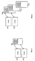
FIG. 4a and FIG. 4b illustrates exemplary encryption and corresponding
decryption tables for a transmitter side and a receiver side in accordance with an
embodiment of the invention.
FIG. 4c and FIG. 4d illustrates exemplary encoding and decoding tables for a
transmitter side and a receiver side in accordance with an embodiment of the invention.
FIG. 4e and FIG. 4f illustrates exemplary combined encryption and decryption
tables for a transmitter side and a receiver side in accordance with an embodiment of
the invention.
FIG. 4g and FIG. 4h illustrates exemplary combined encoding and decoding
tables for a transmitter side and a receiver side in accordance with an embodiment of
the invention.
FIG. 4g and FIG. 4h illustrates an exemplary combined encryption, decryption,
encoding and decoding tables for a transmitter side and a receiver side in accordance
with an embodiment of the invention.
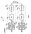
FIG. 5 is a block diagram of a system 500 for coding information in a
communication channel in accordance with an embodiment of the invention
DETAILED DESCRIPTION OF THE INVENTION
Aspects of the invention provide a method and system for coding information in a
communication channel. More particularly, aspects of the invention provide an method
and system for synchronous running encryption and/or encoding and corresponding
decryption and decoding in a communication channel or link. Aspects of the method
may include encoding and/or encrypting a first data using a first or second encoding
table and/or a first or second encryption table. The method may indicate which one of
the first or second encoding tables or which one of the first or second encryption tables
were utilized for encoding and/or encrypting the first data. The encoded and/or
encrypted first data may subsequently be transferred downstream and decoded by
synchronous decoder/decryptor using a corresponding decoding and/or decryption
table. The corresponding decoding and/or decryption table may be determined based
on the indicated first and/or second encoding and/or encrypting tables
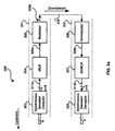
FIG. 3a is a block diagram of an exemplary digital communication link 300 for
performing synchronous encoding/encryption and decoding/decryption at the physical
level, in accordance with an embodiment of the invention. Referring to FIG. 3a, there is
shown a digital communication link 300, which may include a transmitter side 301 and a
receiver side 302. FIG. 3a illustrates a half-duplex or one-way transmit to receive link.
The transmitter side 301 may include a synchronous encoder/encryptor block 303, a
multiplexer 304, and a modulator 305. The receiver side 302 may include a
demodulator 306, a demultiplexer 307, and a synchronous decoder/decryptor block 308.
The transmitter side 301 and the receiver side 302 may be coupled by the link
infrastructure 310.
In accordance with an embodiment of the invention, both sides of the digital
communication link may have both a transmitter side and a receiver side, operating in
full duplex mode. In this regard, a transceiver may be adapted to simultaneously
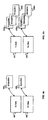
transmit and receive data. FIG. 3b is a block diagram 325 of the exemplary digital
communication link of FIG. 3a illustrating a duplex configuration in accordance with an
embodiment of the invention. Referring to FIG. 3b, there is shown a first transceiver
block 321 and a second transceiver block 322. The first transceiver block 321 may
include a transmitter block 321a and a receiver block 321b. The second transceiver
block 322 may include a transmitter block 322a and a receiver block 322b. The
transmitter block 321a of first transceiver block 321 and the transmitter block 322a of
the second transceiver block 322 may be configured to operate in a manner similar to
the transmitter side 301 of FIG. 3a. Similarly, the receiver block 321b of first
transceiver block 321 and the receiver block 322b of the second transceiver block 322
may be configured to operate in a manner similar to the receiver side 302 of FIG. 3a.
Referring to FIG. 3a, the synchronous encoder/encryptor block 303 may be
adapted to receive raw unencrypted data bytes and encode and/or encrypt the raw
unencrypted data bytes to generate datastream 311a comprising n-bit codewords
and/or control words, for example. The resulting coded datastream 311a may be
multiplexed into a serial bitstream 309a by the multiplexer 304. The resulting
multiplexed serial bitstream 309a may subsequently be transferred to the modulator 305
for processing. The modulator 305 may perform digital-to-analog conversion on the
serial bitstream 309a, resulting in an equivalent or corresponding bitstream 309b. The
resulting analog serial bitstream 309b may be transferred to the receiver side 302 via
the link infrastructure or loopback 310. In certain instances, a data or control word
which is transferred to the synchronous encoder/encryptor 303 may have already been
encrypted by an upstream component of the digital communication link 300. As a
result, the synchronous encoder/encryptor 303 may be adapted to further encrypt the
previously encrypted data or control word.
The demodulator 306 on the receiver side 302 may be adapted to receive the
analog serial bitstream 309b transferred from the transmitter side 301. The
demodulator 306 may perform an analog-to-digital conversion on the received serial
bitstream 309b, resulting in a serial digital bitstream 309c. The resulting serial digital
bitstream 309c generated by the demodulator 306 may be transferred to the
demultiplexer 307 for processing. The demultiplexer 307 may demultiplex the serial
digital bitstream 309c by executing the opposite of the multiplexing function performed
by multiplexer 304.
The demultiplexer 307 may translate the serial bitstream 309c back into n-bit
coded words. For example, in the case of gigabit Ethernet, the demultiplexer 307 may
translate the serial bitstream 309c back into 10-bit coded words. The n-bit coded words
produced by the demultiplexer 307 may subsequently be transferred to the decoder 308
for processing. The decoder 308 may execute the opposite of the encoder function
performed by the encoder 303. In this regard, the decoder 308 may convert the n-bit
coded words back into 8-bit unencoded bytes. These 8-bit unencoded bytes, if
previously encrypted, may be decrypted by an upstream component of the digital
communication link 300, for example.
The encoded/encrypted data word generated by the encoder 303 may be
processed through the multiplexer 304 and modulator 305, transmitted over the link
infrastructure 310, and processed through the demodulator 306 and demultiplexer 307.
The demultiplexed encoded and/or encrypted data word may be transferred to the
synchronous decoder/decryptor 308 for processing. In accordance with an embodiment
of the invention, the synchronous encoder/encryptor block 303 may be configured to
operate in a manner that is synchronous with the operation of the decoder/decryptor
308. In this regard, the synchronous manner of operation may include utilizing the
same encryption scheme and/or encoding scheme on a data word that is to be encoded
and its corresponding encoded equivalent when it is to be decoded and/or decrypted.
Accordingly, the decoder/decryptor 308 is synchronized with the encoder/encryptor 303
and, therefore, uses a corresponding table to decode and decrypt the
encoded/encrypted data word.
For illustrative purposes, consider a case where an 8-bit unencoded and
unencrypted data word, for example 0x09 or D9.0, is received by the synchronous
encoder/encryptor block 303 for encoding and/or encryption. In this case, three
scenarios may be possible. In the first scenario, on the transmitter side 301, the
synchronous encoder/encryptor block 303 may be configured to encode the unencoded
and unencrypted data word D9.0. On the receiver side 302, the synchronous
decoder/decryptor block 308 may be configured to decode an encoded representation
of the data word D9.0 corresponding to the first scenario. In the second scenario, on
the transmitter side 301, the synchronous encoder/encryptor block 303 may be
configured to encrypt the unencoded and unencrypted data word D9.0. On the receiver
side 302, the synchronous decoder/decryptor block 308 may be configured to decrypt a
decrypted representation of the data word D9.0 corresponding to the second scenario.
Finally, in the third scenario, on the transmitter side 301, the synchronous
encoder/encryptor block 303 may be configured to encode and encrypt the unencoded
and unencrypted data word D9.0. On the receiver side 302, the synchronous
decoder/decryptor block 308 may be configured to decode and decrypt an encoded and
encrypted representation of the data word D9.0 corresponding to the third scenario.
In order to encode and/or encrypt the unencoded or unencrypted data and/or
control words, the encoder/encryptor block 303 may be adapted to utilize at least one
encryption algorithm or scheme and at least one encoding algorithm or scheme for
encryption and encoding on the transmitter side 301. Similarly, at least one
corresponding decryption algorithm or scheme and at least one corresponding decoding
algorithm or scheme may be utilized in a synchronous manner on the receiver side 302.
The encryption, decryption, encoding and/or decoding algorithms or schemes may be
implemented in software, hardware or a combination of hardware or software.
Notwithstanding, at least one encryption table may be maintained for use by the
synchronous encoder/encryptor block 303 and at least one decryption table may be
maintained for use by the synchronous decoder/decryptor block 308. In this case, the
encryption table maintained for use by the synchronous encoder/encryptor block 303
may correspond with the decryption table maintained for use by the synchronous
decoder/decryptor block 308. The encryption, decryption, encoding and/or decoding
tables may be stored, for example, in ROM, RAM, or flash memory as lookup tables.
FIG. 4a and FIG. 4b illustrates exemplary encryption and corresponding
decryption tables for a transmitter side and a receiver side in accordance with an
embodiment of the invention. Referring to FIG. 4a, there is shown a transmitter side
401, a receiver side 402, a encryption table 404 and a corresponding decryption table
406. The encryption table 404 may be maintained for use by the transmitter side 401.
Similarly, the corresponding decryption table 406 may be maintained for use by the
receiver side 402. Referring to FIG. 4b, there is shown a transmitter side 401, a
receiver side 402, a plurality of encryption tables 404a, ..., 404n and a plurality of
corresponding decryption tables 406a, ..., 406n. The encryption tables 404a, ..., 404n
may be maintained for use by the transmitter side 401. Similarly, the plurality of
corresponding decryption tables 406a, ..., 406n may be maintained for use by the
receiver side 402.
At least one encoding table may be maintained for use by the synchronous
encoder/encryptor block 303 and at least one decoding table may be maintained for use
by the synchronous decoder/decryptor block 308. In this case, the encoding table
maintained for use by the synchronous encoder/encryptor block 303 may correspond
with the decryption table maintained for use by the synchronous decoder/decryptor
block 308.
FIG. 4c and FIG. 4d illustrates exemplary encoding and decoding tables for a
transmitter side and a receiver side in accordance with an embodiment of the invention.
Referring to FIG. 4c, there is shown a transmitter side 401, a receiver side 402, a
encoding table 408 and a corresponding decoding table 410. The encoding table 408
may be maintained for use by the transmitter side 401. Similarly, the corresponding
decoding table 410 may be maintained for use by the receiver side 402. Referring to
FIG. 4d, there is shown a transmitter side 401, a receiver side 402, a plurality of
encoding tables 408a, ..., 408n and a plurality of corresponding decoding tables 410a,
..., 410n. The encoding tables 408a, ..., 408n may be maintained for use by the
transmitter side 401. Similarly, the plurality of corresponding decoding tables 410a, ...,
410n may be maintained for use by the receiver side 402.
In another aspect of the invention, a combined encryption and decryption table
may be maintained for use by the encoder/encryptor block 303 and the
decoder/decryptor block 308. Similarly, a combined encoding and decoding table may
be maintained for use by the encoder/encryptor block 303 and the decoder/decryptor
block 308. Additionally, a single encryption, encoding, decryption and decoding table
may be maintained for use by both the encoder/encryptor block 303 and the
decoder/decryptor block 308.
FIG. 4e and FIG. 4f illustrates exemplary combined encryption and decryption
tables for a transmitter side and a receiver side in accordance with an embodiment of
the invention. Referring to FIG. 4e, there is shown a transmitter side 401, a receiver
side 402, a combined encryption and decryption table 412. The combined encryption
and decryption table 412 may be utilized by both the transmitter side 401 and the
receiver side 402. In this regard, the combined encryption and decryption table may be
stored in a location that may be accessible by both the transmitter side 401 and the
receiver side 402. Referring to FIG. 4f, there is shown a plurality of combined
encryption and decryption tables 412a,..., 412n. The plurality of combined encryption
and corresponding decryption tables 412a, ..., 412n may be utilized by both the
transmitter side 401 and the receiver side 402. In this regard, the plurality of combined
encryption and decryption tables may be stored in a location that may be accessible by
both the transmitter side 401 and the receiver side 402.
Notwithstanding, in one aspect of the invention, even though a combined or
plurality of combined encryption and corresponding decryption tables may be
maintained for use by the transmitter side 401 and the receiver side 402, local copies of
the table 412 may be maintained by each of the transmitter side 401 and the receiver
side 402. In this regard, a cached copy, for example, of at least a portion of the table
412 may be locally maintained by the transmitter side 401. Similarly, a cached copy, for
example, of at least a corresponding portion of the table 412 may be locally maintained
by the transmitter side 401.
FIG. 4g and FIG. 4h illustrates exemplary combined encoding and decoding
tables for a transmitter side and a receiver side in accordance with an embodiment of
the invention. Referring to FIG. 4g, there is shown a transmitter side 401, a receiver
side 402, a combined encoding and decoding table 414. The combined encoding and
decoding table 412 may be utilized by both the transmitter side 401 and the receiver
side 402. In this regard, the combined encoding and decoding table may be stored in a
location that may be accessible by both the transmitter side 401 and the receiver side
402. Referring to FIG. 4g, there is shown a plurality of combined encoding and
decoding tables 414a,..., 414n. The plurality of combined encoding and corresponding
decoding tables 414a, ..., 414n may be utilized by both the transmitter side 401 and the
receiver side 402. In this regard, the plurality of combined encoding and decoding
tables may be stored in a location that may be accessible by both the transmitter side
401 and the receiver side 402.
Notwithstanding, in one aspect of the invention, even though a combined or
plurality of combined encoding and corresponding decoding tables may be maintained
for use by the transmitter side 401 and the receiver side 402, local copies of the table
414 may be maintained by each of the transmitter side 401 and the receiver side 402.
In this regard, a cached copy, for example, of at least a portion of the table 414 may be
locally maintained by the transmitter side 401. Similarly, a cached copy, for example, of
at least a corresponding portion of the table 414 may be locally maintained by the
transmitter side 401.
FIG. 4g and FIG. 4h illustrates an exemplary combined encryption, decryption,
encoding and decoding tables for a transmitter side and a receiver side in accordance
with an embodiment of the invention. Referring to FIG. 4g, there is shown a transmitter
side 401, a receiver side 402 and a combined encryption, decryption, encoding and
decoding table 416. The combined encryption, decryption, encoding and decoding
table 416 may be utilized by both the transmitter side 401 and the receiver side 402. In
this regard, the combined encryption, decryption, encoding and decoding table 416 may
be stored in a location that may be accessible by both the transmitter side 401 and the
receiver side 402. Referring to FIG. 4g, there is shown a transmitter side 401, a
receiver side 402 and a plurality of combined encryption, decryption, encoding and
decoding tables 416a, ..., 416n. The plurality of combined encryption, decryption,
encoding and decoding tables 416a, ..., 416n may be utilized by both the transmitter
side 401 and the receiver side 402. In this regard, the plurality of combined encryption,
decryption, encoding and decoding table 416a, ..., 416n may be stored in a location that
may be accessible by both the transmitter side 401 and the receiver side 402.
The exemplary tables of figures FIG. 4a through FIG. 4j may contain at least
some of the entries which are in the 8B10B encoding table. Notwithstanding, at least
some of the entries in the exemplary tables of FIG. 4a through FIG. 4j may be different
since the encoded data may also be encrypted. Accordingly, each of the tables of FIG.
4a through FIG. 4j that are utilized on the transmitter side 301, whether it contains
encoded and/or encrypted data, may have a corresponding decoding and/or decryption
table, which may be utilized by the receiver side 302. In cases where the encryption
and decryption tables are combined, then the combined tables may contain
corresponding decryption and encryption entries. For example, a combined encryption
and decryption table may contain entries for mapping an unencrypted data word to an
encrypted data word, and for mapping an encrypted data word back to its corresponding
unencrypted data word. In the cases where the encoding and decoding tables are
combined, then the combined tables may contain corresponding decoding and encoding
entries. For example, a combined encoding and decoding table may contain entries for
mapping an unencoded control word to an encoded control word, and for mapping an
encoded control word back to its corresponding unencoded control word.
The synchronous encoder/encryptor block 303 may be configured to generate
encoded and/or encrypted data and/or control words from the encoding and/or
encryption tables. The encoded and/or encrypted data and/or control words may be
processed by the multiplexer 304 and modulated onto the link infrastructure 310 by the
modulator block 305. Upon receipt by the receiver 302, demodulator 306 may
demodulate the received signal. The resulting signal 309c may then be demultiplexed
by the demultiplexer 307, resulting in 10-bit encoded and/or encrypted data and/or
control words. The synchronous decoder/decryptor block 308 may be synchronized
with the synchronous encoder/encryptor block 303 and, therefore, uses a corresponding
table and/or table entry to decode and/or decrypt the encoded/encrypted data word.
In one aspect on the invention, whenever a next data word enters the
synchronous encoder/encryptor 303, a new table may be utilized by the synchronous
encoder/encryptor 303 to encode and/or encrypt the next data word. Because the
decoder/decryptor 308 is synchronized to the encoder/encryptor 303, the new table may
also be utilized by the decoder/decryptor 308 on the next data word. In another aspect
of the invention, a receiver may be adapted to determine based on the received data, a
corresponding decryption and/or encoding table that may be used to decrypt and/or
decode the received data. Accordingly, the transmitter 301 may be adapted to embed
various information in the encrypted and/or encoded data that may indicate to a
receiver, which table should be utilized for decrypting and/or decoding encoded data.
Specifically, the synchronous encoder/encryptor block 303 may be adapted to encrypt
and/or encode various information in the encrypted and/or encoded data that may
indicate to the synchronous decoder/decryptor block 308, which table should be utilized
for decrypting and/or decoding encoded data.
For example, in FIG. 4b, encryption table 404a and decryption table 406a may be
corresponding tables. Accordingly, the transmitter side 401 may embed information in
the encrypted data, which may indicate that encryption table 404a and decryption table
406a are corresponding tables. Accordingly, when the receiver side 402 receives the
encoded information, the receiver side 402 will determine based on the received
encoded information, that table 406a should be utilized for decrypting the encrypted
data. Similarly, in FIG. 4b, for example, encryption table 408b and decryption table
410b may be corresponding tables. Accordingly, the transmitter side 401 may embed
information in the encrypted data, which may indicate that encryption table 408b and
decryption table 410b are corresponding tables. Accordingly, when the receiver side
402 receives the encoded information, the receiver side'402 will determine based on the
received encoded information, that table 410b should be utilized for decrypting the
encrypted data. In this manner, a synchronous encoding/decoding and
decoding/decrypting system is provided.
In cases where the corresponding encryption, decryption, encoding and decoding
entries may be located in the same table, then the corresponding encoding and/or
encryption and decoding and/or decryption data may be extracted from the mappings
for a particular table. Referring to FIG. 4j and FIG. 3, for example, if a synchronous
encoder/encryptor of the transmitter side utilizes table 416b for encryption and
encoding, it may embed control information in the encoded data to signify that table
416b was used for encryption and encoding. The receiver side 402 may decode the
received decrypted and encoded signal and determine based on the embedded control
information that table 416b should be utilized for decryption and decoding. Accordingly,
a synchronous decoder/decryptor for the receive side 402 may utilize corresponding
decryption and decoding entries in table 416b for decrypting and decoding received
signal.
In one embodiment of the invention, the embedding of control information in the
encrypted and/or encoded data may be utilized as an in-band channel. In this regard,
the in-band communication may be utilized for controlling the operation of any one or
more of the synchronous encoder/encryptor block 303, the synchronous
decoder/decryptor block 308, the multiplexer 304, the demultiplexer 307, the modulator
305 and/or the demodulator 306. The in-band channel may be utilized for flow control,
for example. Accordingly, a parity error, for example, may be inserted in the bitstream
of an encoded or encrypted signal to provide flow control.
Synchronization of tables between the synchronous encoder/encryptor 303 and
the synchronous decoder/decryptor 308 may be accomplished by transmitting
synchronization data between the synchronous encoder/encryptor 303 and the
synchronous decoder/decryptor 308 via overlayed secondary communication channel
as described U.S. Provisional Application 60/446,894 filed on February 12, 2003, which
is incorporated herein by reference in its entirety. Synchronization of tables between
the synchronous encoder/encryptor 303 and the synchronous decoder/decryptor 308
may also be achieved by utilizing spare link bandwidth as described in U.S. Provisional
Application 60/448,703 filed on February 18, 2003. However, the invention is not limited
in this regard and other synchronization techniques may also be utilized. For example,
upon initialization of communication over the link, normal 8B10B encoding/decoding
may be used without encryption until a running synchronization is established, at which
point, synchronous running encryption and encoding may commence.
Although the synchronous encoder/encryptor block 303 may be adapted to
switch to a new table to encode and/or encrypt a next data word, the invention is not so
limited. Accordingly, the synchronous encoder/encryptor block 303 and
decoder/decryptor block 308 may be synchronized to switch to a new table for blocks of
data words instead of switching for every data word. Other synchronous switching
schemes may also be utilized. For example, various block sizes for the data words may
be established and the block sizes may be predefined or may be dynamically altered.
Dynamic alteration may permit the various encoding and/or encryption schemes to be
utilized based on channel conditions, for example. Additionally, this may also be utilized
to provide more reliable transmission over the digital communication link 300 by further
controlling DC balance, maximum run length, maximum RDS, and transition density.
Additionally, separate code groups may also be provided for controlling signaling and
providing code groups synchronization.
FIG. 5 is a block diagram of a system 500 for coding information in a
communication channel in accordance with an embodiment of the invention. Referring
to FIG. 5, there is shown a transmit side 501 and a receive side 502. The transmit side
501 may include a synchronous encoder/encryptor block or unit 503, a multiplexer
(MUX) 504 and a modulator 505. The synchronous encoder/encryptor block or unit 503
may include an integrated synchronous encoder 503a and synchronous encryptor 503b.
The synchronous encryptor block 503b may be any encryption engine such as a DES or
3 DES engine for example. The receive side 502 may include a synchronous a
demodulator 506, a demultiplexer (DEMUX) 507 and a decoder/decryptor block or unit
508. The synchronous decoder/decryptor block or unit 508 may include an integrated
synchronous decoder 508a and synchronous decryptor 508b. The synchronous
decryptor block 508b may be any encryption engine such as a DES or 3 DES engine,
for example.
Notwithstanding, the synchronous encoder 503a and/or the synchronous
encryptor 503b may encode and/or encrypt a first data using a first or second encoding
table and/or a first or second encryption table. The synchronous encoder 503a and/or
synchronous encryptor 503b may indicate which one of the first or second encoding
tables or which one of the first or second encryption tables were utilized for encoding
and/or encrypting the first data. After multiplexing by the MUX 504, the modulator 505
may modulate and transfer the encoded and/or encrypted first data downstream.
The synchronous decoder 508a and/or the synchronous decryptor 508b may
subsequently determine which table was utilized for encoding and/or encrypting the first
data. The synchronous decoder 508a and/or the synchronous decryptor 508b may
synchronously decode and/or decrypt the encoded and/or encrypted first data using a
first decoding table and/or first decryption table corresponding to the first or second
encoding table and/or the first and second encryption table, respectively. The
synchronous encoder 503a and/or synchronous encryptor 503b may generate
information to indicate which table or tables were utilized to encode and/or encrypt the
first data. The generated information may be embedded in the encoded and/or
encrypted first data. The modulator 505 may modulate and transfer the generated
information via an in-band communication channel. The modulator 505 may also
modulate and transfer the generated information with the encoded and encrypted first
data. The demodulator 506 may receive and demodulate the transferred information,
which may be utilized for synchronously decoding and/or decrypting the encoded and/or
encrypted first data.
The synchronous encoder 503a and/or synchronous encryptor 503b may encode
and/or encrypt a second data using the first or second encoding table, or a third
encoding table and/or the first or second encryption table, or a third encryption table.
The synchronous encoder 503a and/or synchronous encryptor 503b may indicate which
one of the first, second, or third encoding tables and/or the first, second or third
encryption tables, were utilized for encoding and/or encrypting the second data. The
modulator 505 may modulate and transfer the encoded and/or encrypted second data
downstream. After demultiplexing by the demultiplexer 507, the synchronous decoder
508a and/or the synchronous decryptor 508b may subsequently determine which table
was utilized for encoding and/or encrypting the second data. The synchronous decoder
508a and/or the synchronous decryptor 508b may synchronously decode and/or decrypt
the encoded and/or encrypted second data using the first decoding or second decoding
tables and/or the first or second decryption tables corresponding to the first, second or
third encoding tables and/or the first, second and/or third encryption tables, respectively.
The synchronous encoder 503a and/or synchronous encryptor 503b may
generate information to indicate which table or tables were utilized to encode and/or
encrypt the second data. The modulator 505 may modulate and transfer the generated
information for the second data via an in-band communication channel. The modulator
505 may modulate and transfer the generated information along with the encoded and
encrypted second data. The demodulator 506 may receive and demodulate the
transferred information, which may be utilized for synchronously decoding and/or
decrypting the encoded and/or encrypted second data.
In summary, a method and system provide running encoding and encryption on a
transmit side of a digital communication link that is synchronous with running decoding
and decryption on a receive side of the digital communication link. Accordingly, in one
embodiment the synchronous decoder/decryptor 508 synchronously switches the tables
to correspond with the encoding and/or decoding of the data by the encoding and/or
decoding synchronous encoder/encryptor unit 503. The tables are designed and may
be utilized by an encoder/encryptor and/or a decoder/decryptor in a synchronous
manner to provide encoding/decoding for more reliable transmission and
encryption/decryption for more secure communication at the physical level. Even
though 8B10B encoding is utilized to illustrate various aspects and/or embodiments of
synchronous running encryption and encoding, synchronous running encryption and
encoding may also be utilized with other encoding schemes.
While the invention has been described with reference to certain embodiments, it
will be understood by those skilled in the art that various changes may be made and
equivalents may be substituted without departing from the scope of the invention. In
addition, many modifications may be made to adapt a particular situation or material to
the teachings of the invention without departing from its scope. Therefore, it is intended
that the invention not be limited to the particular embodiment disclosed, but that the
invention will include all embodiments falling within the scope of the appended claims.
Accordingly, the present invention may be realized in hardware, software, or a
combination of hardware and software. The present invention may be realized in a
centralized fashion in one computer system, or in a distributed fashion where different
elements are spread across several interconnected computer systems. Any kind of
computer system or other apparatus adapted for carrying out the methods described
herein is suited. A typical combination of hardware and software may be a general-purpose
computer system with a computer program that, when being loaded and
executed, controls the computer system such that it carries out the methods described
herein.
The present invention may also be embedded in a computer program product,
which comprises all the features enabling the implementation of the methods described
herein, and which when loaded in a computer system is able to carry out these
methods. Computer program in the present context means any expression, in any
language, code or notation, of a set of instructions intended to cause a system having
an information processing capability to perform a particular function either directly or
after either or both of the following: a) conversion to another language, code or
notation; b) reproduction in a different material form.
While the present invention has been described with reference to certain
embodiments, it will be understood by those skilled in the art that various changes may
be made and equivalents may be substituted without departing from the scope of the
present invention. In addition, many modifications may be made to adapt a particular
situation or material to the teachings of the present invention without departing from its
scope. Therefore, it is intended that the present invention not be limited to the particular
embodiment disclosed, but that the present invention will include all embodiments falling
within the scope of the appended claims.