EP1469598A1 - Analogue system of generating quadrature signals - Google Patents
Analogue system of generating quadrature signals Download PDFInfo
- Publication number
- EP1469598A1 EP1469598A1 EP01275063A EP01275063A EP1469598A1 EP 1469598 A1 EP1469598 A1 EP 1469598A1 EP 01275063 A EP01275063 A EP 01275063A EP 01275063 A EP01275063 A EP 01275063A EP 1469598 A1 EP1469598 A1 EP 1469598A1
- Authority
- EP
- European Patent Office
- Prior art keywords
- frequency
- signals
- inverter
- transformer
- analog
- Prior art date
- Legal status (The legal status is an assumption and is not a legal conclusion. Google has not performed a legal analysis and makes no representation as to the accuracy of the status listed.)
- Withdrawn
Links
- 238000004804 winding Methods 0.000 claims abstract description 10
- 230000010287 polarization Effects 0.000 claims description 5
- 230000035945 sensitivity Effects 0.000 claims description 2
- 230000000712 assembly Effects 0.000 description 1
- 238000000429 assembly Methods 0.000 description 1
- 230000001143 conditioned effect Effects 0.000 description 1
- 238000010586 diagram Methods 0.000 description 1
- 238000006073 displacement reaction Methods 0.000 description 1
- 230000000694 effects Effects 0.000 description 1
- 238000001914 filtration Methods 0.000 description 1
- 238000012986 modification Methods 0.000 description 1
- 230000004048 modification Effects 0.000 description 1
- 230000001151 other effect Effects 0.000 description 1
Images

Classifications
-
- H—ELECTRICITY
- H03—ELECTRONIC CIRCUITRY
- H03B—GENERATION OF OSCILLATIONS, DIRECTLY OR BY FREQUENCY-CHANGING, BY CIRCUITS EMPLOYING ACTIVE ELEMENTS WHICH OPERATE IN A NON-SWITCHING MANNER; GENERATION OF NOISE BY SUCH CIRCUITS
- H03B27/00—Generation of oscillations providing a plurality of outputs of the same frequency but differing in phase, other than merely two anti-phase outputs
-
- H—ELECTRICITY
- H03—ELECTRONIC CIRCUITRY
- H03B—GENERATION OF OSCILLATIONS, DIRECTLY OR BY FREQUENCY-CHANGING, BY CIRCUITS EMPLOYING ACTIVE ELEMENTS WHICH OPERATE IN A NON-SWITCHING MANNER; GENERATION OF NOISE BY SUCH CIRCUITS
- H03B19/00—Generation of oscillations by non-regenerative frequency multiplication or division of a signal from a separate source
- H03B19/16—Generation of oscillations by non-regenerative frequency multiplication or division of a signal from a separate source using uncontrolled rectifying devices, e.g. rectifying diodes or Schottky diodes
-
- H—ELECTRICITY
- H03—ELECTRONIC CIRCUITRY
- H03H—IMPEDANCE NETWORKS, e.g. RESONANT CIRCUITS; RESONATORS
- H03H7/00—Multiple-port networks comprising only passive electrical elements as network components
- H03H7/18—Networks for phase shifting
- H03H7/21—Networks for phase shifting providing two or more phase shifted output signals, e.g. n-phase output
-
- H—ELECTRICITY
- H03—ELECTRONIC CIRCUITRY
- H03H—IMPEDANCE NETWORKS, e.g. RESONANT CIRCUITS; RESONATORS
- H03H7/00—Multiple-port networks comprising only passive electrical elements as network components
- H03H7/42—Networks for transforming balanced signals into unbalanced signals and vice versa, e.g. baluns
- H03H7/422—Networks for transforming balanced signals into unbalanced signals and vice versa, e.g. baluns comprising distributed impedance elements together with lumped impedance elements
-
- H—ELECTRICITY
- H03—ELECTRONIC CIRCUITRY
- H03H—IMPEDANCE NETWORKS, e.g. RESONANT CIRCUITS; RESONATORS
- H03H11/00—Networks using active elements
- H03H11/02—Multiple-port networks
- H03H11/16—Networks for phase shifting
- H03H11/22—Networks for phase shifting providing two or more phase shifted output signals, e.g. n-phase output
-
- H—ELECTRICITY
- H03—ELECTRONIC CIRCUITRY
- H03J—TUNING RESONANT CIRCUITS; SELECTING RESONANT CIRCUITS
- H03J2200/00—Indexing scheme relating to tuning resonant circuits and selecting resonant circuits
- H03J2200/38—Control voltage applied to the cathode of the varicap
Definitions
- This invention relates to an analog generator system for releasing quadrature signals using frequency division as an essential operating principle.
- quadrature analog signals are essential for the correct operation of the current communications electronic systems, namely for the RF communication systems (as the best exponent we could consider the GSM, UMTS digital mobile telephony systems).
- the information is coded as symbols which are constructed suitably matching phase and quadrature signals.
- the patent US 5,983,082 relates to a generator system releasing quadrature signals which uses the principle of the frequency division but it makes it by means of a digital frequency divider (assembly Flip-Flop master slave). In addition it does not directly use the quadrature signals released but it uses only one of them and an additional shift network. Last, the system implemented mandatorily requires to be polarized to operate.
- the patent US 5,808,499 relates to a generator system releasing quadrature signals which like the former, also uses the principle of the frequency division but although it uses a double frequency input analog signal, releases digital signals.
- the polarization is also essential to correctly operate.
- the patent US 5,491,725 relates to a generator system releasing quadrature signals which does not use the frequency division principle because it uses a filtering and shift match to release the said quadrature signals.
- the patent US 5,808,498 discloses a phase displacement circuit which can be used as a part of a system generating quadrature clock signals.
- the said signals are digital and are not released using the frequency division principle.
- the patent US 6,157,235 relates to a system releasing quadrature signals which do not use the principle of the frequency division.
- the generator is not analog but digital.
- the generation pattern proposed by the invention is fully analog and does not pose above problem of dependence on the frequency of the quadrature signals released because ideally quadrature signals could be released for any frequency, although in the practise, as it will be seen, the range of useful frequency will be conditioned by the characteristics of analog frequency dividers used.
- This invention provides a system for releasing two quadrature signals including two analog frequency dividers respectively driven by two opposed phase signals obtained in the preferred version by an analog inverter.
- the steps of the system can be schematized as follows:
- the outputs s 1 and s 2 are analog signals which for the above mentioned have exactly the same frequency except that they have a 90° shift, that is to say they are quadrature signals.
- the output signals of the two frequency dividers are at +/- 90° shift (+/- ⁇ /2).
- the said frequency dividers are constituted from connecting with the end of the secondary of the differential transformer, by an inverter transformer, two varactor diodes having a variable capacity connected to the end of each winding of the said inverter transformer and a no inverter transformer.
- the analog generator system of quadrature signals is characterized in that it comprises a first analog frequency divider and a second analog frequency divider each of them fed by a d 1 and d 2 signals, respectively which are analog, of frequency 2f and with a 180° shift between them so that two output signals s 1 and s 2 are obtained which are analog, with a f frequency and which are quadrature signals (that means with a 90° shift between them).
- an inverter is used fed by a voltage signal d.
- the said inverter is characterized in that it is constituted by a single differential transformer 1 at the ends of its secondary winding are respectively associated the said first and second frequency dividers.
- the inverter 1 chosen has the property of being passive therefore it has to distribute the capacity of the input signal at 2f to a given extent between the two output signals, for example, it could distribute it fifty-fifty, constituting by itself an attenuation with respect to the input signal, in addition to be able to introduce other attenuations due to the losses or other effects.
- first and second frequency dividers in the example of Fig. 3, they are constituted, each, from the connection with the end of the secondary of the differential transformer 1, by an inverter transformer 2, 2a, two varactor diodes having a variable capacity 3, 4, 3a, 4a, connected with the end of each of the windings of the said inverter transformer 2, 2a and a no inverter transformer 5, 5a.
- first and second frequency dividers are identical, which determines a symmetry in the architecture because the output signals have same capacity and frequency, although they are quadrature signals.
- all above transformers used as well at the shift step as at the frequency division step will be planar and printed on PCB or directly on the integrated circuit.
- the system is passive, that means, it does not require an external polarization in the classical meaning (which defines it as a contribution of additional power allowing the system to suitably operate), but however, it does optionally admit the use of an external polarization applied to an outlet 14 located at an intermediate point of the secondary winding of the differential transformer 1 (which constitutes the already mentioned inverter) to displace the working frequency band.
- each of the mentioned analog frequency dividers in which the said first and second frequency dividers are constituted from connecting with the end of the secondary of the differential transformer 1 by an inverter transformer 6, two varactors diodes having a variable capacity 7, 8 connected to the end of each winding of the said inverter transformer 6 and in addition arranged in line, connected in opposition, providing a middle point 9 for controlling the capacity though a voltage Vc and a step of gain constituted by a circuit 10 with a global behaviour providing a negative differential impedance so that the said step of gain is applied to offset the losses and to increase this way the sensitivity of the quadrature generator, taking the output signals at terminals of the said varactor diodes.
- the said circuit 10 having a global behaviour contributing a negative differential impedance is constituted by a crossed pair of transistors 11, 12 and a power supply 13.
- Fig. 6 illustrates the said output signals s 1 and s 2 displayed in an oscilloscope screen.
- the invention could be embodied with different implementations on the ground of the accessory modifications mentioned, namely at the step releasing the said signals d 1 and d 2 with a 180° shift.
Landscapes
- Digital Transmission Methods That Use Modulated Carrier Waves (AREA)
Abstract
The invention relates to an analogue system of generating quadrature signals. The inventive system comprises: a)
a first analogue frequency divider; and b) a second analogue frequency divider.Each of said dividers is supplied respectively with
a d1 and d2 analogue signal having a frequency 2f, said signals (d1 and d2) being 180 ° phase shifted relative to each other. In this
way, two analogue output quadrature signals s1 and s2 having frequency f are obtained at the output of each of the aforementioned
frequency dividers, i. e. said signals are 90 ° phase shifted relative to each other. The aforementioned signals (d1 and d2) are obtained
using a differential transformer (1). Moreover, each of the above-mentioned analogue frequency dividers can be formed, from the
connection with the end of the auxiliary differential transformer (1), using an inverting transformer (2, 2a), two variable-capacity
varactor diodes (3, 4, 3a, 4a), which are connected to the end of each of the windings of the inverting transformer (2, 2a), and a
non-inverting transformer (5, 5a).
Description
- This invention relates to an analog generator system for releasing quadrature signals using frequency division as an essential operating principle.
- The availability of quadrature analog signals is essential for the correct operation of the current communications electronic systems, namely for the RF communication systems (as the best exponent we could consider the GSM, UMTS digital mobile telephony systems). In the said electronic systems, the information is coded as symbols which are constructed suitably matching phase and quadrature signals.
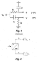
- The usual way to obtain quadrature signals is by means of a shift networks. The principle which appears illustrated in Fig. 1 of the drawings attached is simple: a same signal is introduced in two networks which provoke a shift of respectively 45° and -45°. Therefore, the respective output signals will have a 90° shift. However, the phase networks have a behaviour strongly depending on the frequency this determining that the quadrature signals generation is limited to a very narrow frequency band.
- The patent US 5,983,082 relates to a generator system releasing quadrature signals which uses the principle of the frequency division but it makes it by means of a digital frequency divider (assembly Flip-Flop master slave). In addition it does not directly use the quadrature signals released but it uses only one of them and an additional shift network. Last, the system implemented mandatorily requires to be polarized to operate.
- The patent US 5,808,499 relates to a generator system releasing quadrature signals which like the former, also uses the principle of the frequency division but although it uses a double frequency input analog signal, releases digital signals. In addition, as it occurs in the system of the patent US 5,983,082, the polarization is also essential to correctly operate.
- The patent US 5,491,725 relates to a generator system releasing quadrature signals which does not use the frequency division principle because it uses a filtering and shift match to release the said quadrature signals.
- The patent US 5,808,498 discloses a phase displacement circuit which can be used as a part of a system generating quadrature clock signals. The said signals are digital and are not released using the frequency division principle.
- The patent US 6,157,235 relates to a system releasing quadrature signals which do not use the principle of the frequency division. In addition, the generator is not analog but digital.
- The generation pattern proposed by the invention is fully analog and does not pose above problem of dependence on the frequency of the quadrature signals released because ideally quadrature signals could be released for any frequency, although in the practise, as it will be seen, the range of useful frequency will be conditioned by the characteristics of analog frequency dividers used.
- This invention provides a system for releasing two quadrature signals including two analog frequency dividers respectively driven by two opposed phase signals obtained in the preferred version by an analog inverter.
The steps of the system can be schematized as follows: - 1.- A frequency signal d twice the end working frequency wished feeds the single input of an analog inverter. At its output then two analog signals are obtained which are called herein d1 and d2 of double frequency, one with same sign as the input signal and the other with the opposite sign to that of the input signal, that is to say, with a 180° shift from each other;
- 2.- Then, the first signal d1 is injected to a frequency divider and the second signal d2 is injected to another frequency divider. The said dividers are independent and identical therefore they act exactly in same way on their respective inputs.
-
- The outputs s1 and s2 are analog signals which for the above mentioned have exactly the same frequency except that they have a 90° shift, that is to say they are quadrature signals.
- The principle by which the quadrature is achieved after the division into frequency is mathematically explained below:
- 1.- From the first frequency divider, it is obtained:
input signal output signal ej2wt ejwt - 2.- From the second frequency divider, it is obtained:
input signal output signal ej2wt+/-π ejwt+/-π/2 -
- Therefore, the output signals of the two frequency dividers are at +/- 90° shift (+/-π /2).
- In an example of possible embodiment of the invention, which provides a fully passive assembly, the said frequency dividers are constituted from connecting with the end of the secondary of the differential transformer, by an inverter transformer, two varactor diodes having a variable capacity connected to the end of each winding of the said inverter transformer and a no inverter transformer.
- To best understand the invention, examples of embodiment thereof will be described which have to be considered for illustrating no limiting purpose.
-
- Fig. 1 shows a phase network for generating quadrature signals, according to the prior art.
- Fig. 2 is a diagram showing the principle of the invention.
- Fig. 3 illustrates an example of embodiment of the generator of the invention which can constitute a fully analog passive assembly where in addition every voltage signal at different points of the system are displayed.
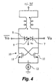
- Fig. 4 is a variation of the implementation of the frequency dividers used.
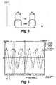
- Fig. 5 shows the bandwidth of the generator of Fig. 3, where the polarization effect of the varactor diodes is indicated.
- Fig. 6 illustrates the shapes of the voltage waves at the outputs of the quadrature generator of Fig. 3.
-
- As illustrated in Fig. 2 and 3, the analog generator system of quadrature signals according to the invention is characterized in that it comprises a first analog frequency divider and a second analog frequency divider each of them fed by a d1 and d2 signals, respectively which are analog, of
frequency 2f and with a 180° shift between them so that two output signals s1 and s2 are obtained which are analog, with a f frequency and which are quadrature signals (that means with a 90° shift between them). - To be able to obtain the said signals d1 and d2, with a 180° shift to each other, in the example proposed in Fig. 3 an inverter is used fed by a voltage signal d. The said inverter is characterized in that it is constituted by a single
differential transformer 1 at the ends of its secondary winding are respectively associated the said first and second frequency dividers. - Anyway, a 180° shift could be achieved using an analog inverter (operational with inverting configuration) , a differential transformer or a coupler built with micro-strip or co-planar lines, depending on the operating frequency. Another possibility would be to directly use as input a generator having a differential output. Any of the said assemblies would be suitable for the purpose of this invention although a solution has been chosen for simplicity's sake of the assembly in addition to other properties which are described below.
- Thus, the
inverter 1 chosen has the property of being passive therefore it has to distribute the capacity of the input signal at 2f to a given extent between the two output signals, for example, it could distribute it fifty-fifty, constituting by itself an attenuation with respect to the input signal, in addition to be able to introduce other attenuations due to the losses or other effects. - An active device could be included at some suitable point of the system which would contribute the power required to offset the said attenuation. With respect to the already mentioned first and second frequency dividers in the example of Fig. 3, they are constituted, each, from the connection with the end of the secondary of the
differential transformer 1, by aninverter transformer said inverter transformer inverter transformer 5, 5a. - It must be emphasized that the said first and second frequency dividers are identical, which determines a symmetry in the architecture because the output signals have same capacity and frequency, although they are quadrature signals.
- With respect to the bandwidth of the system, be understood as the frequency range within which the device behaves as wished, this system is specially designed to work within the frequency range of radio frequency (RF) comprised within approximately 100 MHz and 3 GHz. It is worth to say that due to the fact that the shift is not obtained with the use of phase networks a greater bandwidth is available than in other systems which do use them.
- From above stated up to now, and as the system does not include any digital device or component at its input or output, it results that it is a fully analog system.
- In a preferred implementation all above transformers used as well at the shift step as at the frequency division step will be planar and printed on PCB or directly on the integrated circuit.
- In the example explained in Fig. 3, the system is passive, that means, it does not require an external polarization in the classical meaning (which defines it as a contribution of additional power allowing the system to suitably operate), but however, it does optionally admit the use of an external polarization applied to an
outlet 14 located at an intermediate point of the secondary winding of the differential transformer 1 (which constitutes the already mentioned inverter) to displace the working frequency band. - In Fig. 4, an alternative embodiment is illustrated of each of the mentioned analog frequency dividers in which the said first and second frequency dividers are constituted from connecting with the end of the secondary of the
differential transformer 1 by aninverter transformer 6, two varactors diodes having avariable capacity 7, 8 connected to the end of each winding of thesaid inverter transformer 6 and in addition arranged in line, connected in opposition, providing amiddle point 9 for controlling the capacity though a voltage Vc and a step of gain constituted by acircuit 10 with a global behaviour providing a negative differential impedance so that the said step of gain is applied to offset the losses and to increase this way the sensitivity of the quadrature generator, taking the output signals at terminals of the said varactor diodes. - As illustrated in the said Fig. 4, the said
circuit 10 having a global behaviour contributing a negative differential impedance is constituted by a crossed pair oftransistors - Fig. 6 illustrates the said output signals s1 and s2 displayed in an oscilloscope screen.
- The invention could be embodied with different implementations on the ground of the accessory modifications mentioned, namely at the step releasing the said signals d1 and d2 with a 180° shift.
Claims (12)
- Analog generator system for releasing quadrature signals characterized in that it comprises:each of them fed by a d1 and d2 signals, respectively which are analog, of frequency 2f and the said signals d1 and d2 having a 180° shift between them so that, at the output of each of the said first and second frequency dividers, two output signals s1 and s2 are obtained which are analog, with a frequency f and which are quadrature signals, that means with a 90° shift between them.a) a first analog frequency divider;b) a second analog frequency divider;
- System, according to claim 1, characterized in that it comprises an inverter which is fed by an input signal d, having a frequency 2f provides the said signals d1 and d2 having a frequency 2f and a 180° shift between them.
- System, according to claim 2, characterized in that the said inverter is passive and distributes the capacity of the input signal 2f to a given extent between the two output signals.
- System, according to claim 3, characterized in that the said inverter is constituted by a differential transformer (1).
- System, according to claim 4, characterized in that the said first and second frequency dividers are connected to the respective ends of the secondary winding of the said differential transformer (1).
- System, according to claim 5, characterized in that the said first and second frequency dividers are constituted by a step of tuning to the frequency wished.
- System, according to claim 6, characterized in that the said first and second frequency dividers are constituted, each, from the connection with the end of the secondary of the differential transformer (1), by an inverter transformer (2, 2a), two varactor diodes having a variable capacity (3, 4, 3a, 4a), connected with the end of each of the windings of the said inverter transformer (2, 2a) and a no inverter transformer (5, 5a).
- System, according to claim 6, characterized in that the said first and second frequency dividers are constituted, each, from the connection with the end of the secondary of the differential transformer (1), by an inverter transformer (6), two varactor diodes having a variable capacity (7,8), connected with the end of each of the windings of the said inverter transformer (6) and arranged in line, connected in opposition, providing a middle point (9) for controlling the capacity though a voltage Vc and a step of gain constituted by a circuit (10) with a global behaviour providing a negative differential impedance so that the said step of gain is applied to offset the losses and to increase this way the sensitivity of the quadrature generator, taking the output signals at terminals of the said varactor diodes (7,8).
- System, according to claim 8, characterized in that the said circuit (10) with a global behaviour providing a negative differential impedance is constituted by a crossed pair of transistors (11, 12) and a power supply (13).
- System, according to claim 7 or 8, characterized in that the said first and second frequency dividers are identical, which determines a symmetry in the architecture and the quadrature output signals have same capacity and frequency.
- System, according to claim 4, characterized in that it includes an outlet (14) for applying an external polarization at an intermediate point of the secondary winding of the differential transformer (1) of the inverter allowing to displace through it the working frequency band.
- System, according to claims 4 and 5, characterized in that all above transformers are planar and printed on PCB or directly on the integrated circuit.
Applications Claiming Priority (1)
| Application Number | Priority Date | Filing Date | Title |
|---|---|---|---|
| PCT/ES2001/000497 WO2003055064A1 (en) | 2001-12-20 | 2001-12-20 | Analogue system of generating quadrature signals |
Publications (1)
| Publication Number | Publication Date |
|---|---|
| EP1469598A1 true EP1469598A1 (en) | 2004-10-20 |
Family
ID=8244415
Family Applications (1)
| Application Number | Title | Priority Date | Filing Date |
|---|---|---|---|
| EP01275063A Withdrawn EP1469598A1 (en) | 2001-12-20 | 2001-12-20 | Analogue system of generating quadrature signals |
Country Status (3)
| Country | Link |
|---|---|
| EP (1) | EP1469598A1 (en) |
| AU (1) | AU2002216128A1 (en) |
| WO (1) | WO2003055064A1 (en) |
Cited By (1)
| Publication number | Priority date | Publication date | Assignee | Title |
|---|---|---|---|---|
| EP2430746B1 (en) * | 2009-05-15 | 2017-06-14 | QUALCOMM Incorporated | Receiver with balanced i/q transformer |
Citations (2)
| Publication number | Priority date | Publication date | Assignee | Title |
|---|---|---|---|---|
| EP1225689A2 (en) * | 2001-01-05 | 2002-07-24 | TDK Corporation | Oscillation circuit with voltage-controlled oscillators |
| EP1311061A1 (en) * | 2001-11-08 | 2003-05-14 | Mitsubishi Denki Kabushiki Kaisha | Polyphase signal generator |
Family Cites Families (2)
| Publication number | Priority date | Publication date | Assignee | Title |
|---|---|---|---|---|
| DE3240565C2 (en) * | 1982-11-03 | 1985-12-12 | Telefunken electronic GmbH, 6000 Frankfurt | Direct mixing synchronous receiver |
| DE4433871A1 (en) * | 1994-09-22 | 1996-03-28 | Kathrein Werke Kg | HF amplifier design with suppression of intermodulation interference for electrical industry and communications equipment |
-
2001
- 2001-12-20 EP EP01275063A patent/EP1469598A1/en not_active Withdrawn
- 2001-12-20 WO PCT/ES2001/000497 patent/WO2003055064A1/en not_active Ceased
- 2001-12-20 AU AU2002216128A patent/AU2002216128A1/en not_active Abandoned
Patent Citations (2)
| Publication number | Priority date | Publication date | Assignee | Title |
|---|---|---|---|---|
| EP1225689A2 (en) * | 2001-01-05 | 2002-07-24 | TDK Corporation | Oscillation circuit with voltage-controlled oscillators |
| EP1311061A1 (en) * | 2001-11-08 | 2003-05-14 | Mitsubishi Denki Kabushiki Kaisha | Polyphase signal generator |
Non-Patent Citations (2)
| Title |
|---|
| See also references of WO03055064A1 * |
| TING-PING LIU: "A 6.5 GHz Monolithic CMOS Voltage-Controlled Oscillator", SOLID-STATE CIRCUITS CONFERENCE, 1999. DIGEST OF TECHNICAL PAPERS. ISSCC, 15 February 1999 (1999-02-15), SAN FRANCISCO, CA, USA, pages 404 - 405, XP000862389 * |
Cited By (1)
| Publication number | Priority date | Publication date | Assignee | Title |
|---|---|---|---|---|
| EP2430746B1 (en) * | 2009-05-15 | 2017-06-14 | QUALCOMM Incorporated | Receiver with balanced i/q transformer |
Also Published As
| Publication number | Publication date |
|---|---|
| AU2002216128A1 (en) | 2003-07-09 |
| WO2003055064A1 (en) | 2003-07-03 |
Similar Documents
| Publication | Publication Date | Title |
|---|---|---|
| DE60128311T2 (en) | Adaptive voting apparatus and method for a wireless communication device | |
| US10116281B2 (en) | Power combiner/divider using mutual inductance | |
| CN104659493A (en) | Metal ring-slot antenna and wireless terminal | |
| JP2002533980A (en) | Antenna switch module | |
| KR100665590B1 (en) | A radio frequency device having a power amplifier circuit and a stabilizer circuit, and a mobile transceiver terminal having such a device. | |
| Zheng | Simultaneous phase-and frequency-tunable hybrid coupler | |
| US4902983A (en) | Nonlinear signal generating circuit and nonlinear compensating device using the same | |
| DE102021214600A1 (en) | VOLTAGE CONTROLLED WIDE BAND OSCILLATOR CIRCUIT | |
| EP1703634B1 (en) | Bias circuit | |
| US7015773B2 (en) | Electronic phase shifter with enhanced phase shift performance | |
| US20080197939A1 (en) | Passive microwave (de)multiplexer | |
| JPH10256809A (en) | Electronically tuned polarized filter | |
| EP1258077B1 (en) | Circuit configuration for direct modulation | |
| KR102675358B1 (en) | In-phase/Quadrature-phase generating device and phase shift device using the same | |
| US6542042B1 (en) | Low power crystal oscillator with feedback resistor pair | |
| US7969210B2 (en) | Electronic circuit, frequency divider and radio set | |
| DE60033762T2 (en) | Low-consumption, high-frequency oscillator for telecomunication ICs | |
| Phuong et al. | A microwave active filter for nanosatellite’s receiver front-ends at S-band. | |
| US6774737B1 (en) | High Q resonator circuit | |
| KR102845676B1 (en) | High-power rf antenna tuning switch with uniform characteristics to external voltage | |
| WO1995016267A2 (en) | Resonant balun with arbitrary impedance transformation ratio | |
| KR0168910B1 (en) | Electric power distributor synthesizer using duplication coupling transmission line pair | |
| KR100262816B1 (en) | Pll synthesizer for telecommunication terminal using directional coupler | |
| JP4066295B2 (en) | Even harmonic mixer | |
| Phương | A microwave active filter for nanosatellite’s receiver front-ends at s-bands |
Legal Events
| Date | Code | Title | Description |
|---|---|---|---|
| PUAI | Public reference made under article 153(3) epc to a published international application that has entered the european phase |
Free format text: ORIGINAL CODE: 0009012 |
|
| 17P | Request for examination filed |
Effective date: 20040719 |
|
| AK | Designated contracting states |
Kind code of ref document: A1 Designated state(s): AT BE CH CY DE DK ES FI FR GB GR IE IT LI LU MC NL PT SE TR |
|
| AX | Request for extension of the european patent |
Extension state: AL LT LV MK RO SI |
|
| 17Q | First examination report despatched |
Effective date: 20070404 |
|
| GRAP | Despatch of communication of intention to grant a patent |
Free format text: ORIGINAL CODE: EPIDOSNIGR1 |
|
| STAA | Information on the status of an ep patent application or granted ep patent |
Free format text: STATUS: THE APPLICATION IS DEEMED TO BE WITHDRAWN |
|
| 18D | Application deemed to be withdrawn |
Effective date: 20080619 |