EP1469561A2 - Terminal - Google Patents
Terminal Download PDFInfo
- Publication number
- EP1469561A2 EP1469561A2 EP04008871A EP04008871A EP1469561A2 EP 1469561 A2 EP1469561 A2 EP 1469561A2 EP 04008871 A EP04008871 A EP 04008871A EP 04008871 A EP04008871 A EP 04008871A EP 1469561 A2 EP1469561 A2 EP 1469561A2
- Authority
- EP
- European Patent Office
- Prior art keywords
- terminal
- width direction
- plate
- laid
- protruding piece
- Prior art date
- Legal status (The legal status is an assumption and is not a legal conclusion. Google has not performed a legal analysis and makes no representation as to the accuracy of the status listed.)
- Granted
Links
Images




Classifications
-
- H—ELECTRICITY
- H01—ELECTRIC ELEMENTS
- H01R—ELECTRICALLY-CONDUCTIVE CONNECTIONS; STRUCTURAL ASSOCIATIONS OF A PLURALITY OF MUTUALLY-INSULATED ELECTRICAL CONNECTING ELEMENTS; COUPLING DEVICES; CURRENT COLLECTORS
- H01R13/00—Details of coupling devices of the kinds covered by groups H01R12/70 or H01R24/00 - H01R33/00
- H01R13/02—Contact members
- H01R13/10—Sockets for co-operation with pins or blades
- H01R13/11—Resilient sockets
- H01R13/113—Resilient sockets co-operating with pins or blades having a rectangular transverse section
-
- H—ELECTRICITY
- H01—ELECTRIC ELEMENTS
- H01R—ELECTRICALLY-CONDUCTIVE CONNECTIONS; STRUCTURAL ASSOCIATIONS OF A PLURALITY OF MUTUALLY-INSULATED ELECTRICAL CONNECTING ELEMENTS; COUPLING DEVICES; CURRENT COLLECTORS
- H01R13/00—Details of coupling devices of the kinds covered by groups H01R12/70 or H01R24/00 - H01R33/00
- H01R13/02—Contact members
- H01R13/04—Pins or blades for co-operation with sockets
-
- H—ELECTRICITY
- H01—ELECTRIC ELEMENTS
- H01R—ELECTRICALLY-CONDUCTIVE CONNECTIONS; STRUCTURAL ASSOCIATIONS OF A PLURALITY OF MUTUALLY-INSULATED ELECTRICAL CONNECTING ELEMENTS; COUPLING DEVICES; CURRENT COLLECTORS
- H01R13/00—Details of coupling devices of the kinds covered by groups H01R12/70 or H01R24/00 - H01R33/00
- H01R13/40—Securing contact members in or to a base or case; Insulating of contact members
- H01R13/42—Securing in a demountable manner
- H01R13/422—Securing in resilient one-piece base or case, e.g. by friction; One-piece base or case formed with resilient locking means
- H01R13/4223—Securing in resilient one-piece base or case, e.g. by friction; One-piece base or case formed with resilient locking means comprising integral flexible contact retaining fingers
-
- H—ELECTRICITY
- H01—ELECTRIC ELEMENTS
- H01R—ELECTRICALLY-CONDUCTIVE CONNECTIONS; STRUCTURAL ASSOCIATIONS OF A PLURALITY OF MUTUALLY-INSULATED ELECTRICAL CONNECTING ELEMENTS; COUPLING DEVICES; CURRENT COLLECTORS
- H01R4/00—Electrically-conductive connections between two or more conductive members in direct contact, i.e. touching one another; Means for effecting or maintaining such contact; Electrically-conductive connections having two or more spaced connecting locations for conductors and using contact members penetrating insulation
- H01R4/10—Electrically-conductive connections between two or more conductive members in direct contact, i.e. touching one another; Means for effecting or maintaining such contact; Electrically-conductive connections having two or more spaced connecting locations for conductors and using contact members penetrating insulation effected solely by twisting, wrapping, bending, crimping, or other permanent deformation
- H01R4/18—Electrically-conductive connections between two or more conductive members in direct contact, i.e. touching one another; Means for effecting or maintaining such contact; Electrically-conductive connections having two or more spaced connecting locations for conductors and using contact members penetrating insulation effected solely by twisting, wrapping, bending, crimping, or other permanent deformation by crimping
- H01R4/183—Electrically-conductive connections between two or more conductive members in direct contact, i.e. touching one another; Means for effecting or maintaining such contact; Electrically-conductive connections having two or more spaced connecting locations for conductors and using contact members penetrating insulation effected solely by twisting, wrapping, bending, crimping, or other permanent deformation by crimping for cylindrical elongated bodies, e.g. cables having circular cross-section
- H01R4/184—Electrically-conductive connections between two or more conductive members in direct contact, i.e. touching one another; Means for effecting or maintaining such contact; Electrically-conductive connections having two or more spaced connecting locations for conductors and using contact members penetrating insulation effected solely by twisting, wrapping, bending, crimping, or other permanent deformation by crimping for cylindrical elongated bodies, e.g. cables having circular cross-section comprising a U-shaped wire-receiving portion
- H01R4/185—Electrically-conductive connections between two or more conductive members in direct contact, i.e. touching one another; Means for effecting or maintaining such contact; Electrically-conductive connections having two or more spaced connecting locations for conductors and using contact members penetrating insulation effected solely by twisting, wrapping, bending, crimping, or other permanent deformation by crimping for cylindrical elongated bodies, e.g. cables having circular cross-section comprising a U-shaped wire-receiving portion combined with a U-shaped insulation-receiving portion
Definitions
- This invention belongs to the field of terminals of electric connectors and relates to a terminal having a laid-down protruding piece that exhibits at least one function of a function of guiding the terminal to a predetermined position inside a receiving cell of a housing when the terminal is to be inserted into the receiving cell, a function of being fitted on a flexible piece of the housing and a function of preventing the terminal from being inserted into the housing the other way.
- Japanese Patent Unexamined Publication 2000-231956 discloses a female-type terminal of electric connector.
- the front half of this female-type terminal is approximately formed into a box shape so that the front half can be inserted into a receiving cell of a housing, a port is opened in the front end thereof for accepting a male-type terminal, a connecting part to be connected with an electric wire is provided in the rear thereof, and a contact spring, of which top end extending frontward to press and contact the male-type terminal, is provided inside the female-type terminal.
- the stabilizer is stamped in the form of a protrusion from the inner face toward the outer face, the strength of the rectangular-tube-shaped body will be lowered.
- the retaining piece is formed by bending an extended part of a side wall.
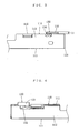
- Fig. 3 is an enlarged partial view of the body of the terminal of the first embodiment seen in the width direction.
- Fig. 6 is an enlarged sectional view of the body of the terminal of the first embodiment seen in the width direction.
- Fig. 7 is a perspective view showing in section a nonwaterproof electric connector of the first embodiment.
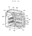
- Fig. 15 is a perspective view showing in section a waterproof electric connector of the second embodiment.
- the body 110 is formed into a rectangular tube that comprises a cross plate 111, a first vertical plate 112 and a second vertical plate 113 both bending from both ends in the width direction of the cross plate 111 and rising to one side of the thickness direction, an inner plate 114 bending from the first vertical plate 112 and extending in the width direction close to the second vertical plate 113, and an outer plate 115 bending from the second vertical plate 113 and extending in the width direction close to the first vertical plate 112 to overlap with the inner plate 114.
- this terminal 100 is of a female-type, an opening 116 is formed at the front in the depth direction of the body 110 by edges of the cross plate 111, the first vertical plate 112, the second vertical plate 113, the inner plate 114 and the outer plate 115.
- Chamfering of such parts include not only the narrow-sense chamfering wherein inclined straight faces are formed but also the R-chamfering (round-chamfering) wherein chamfered faces are formed by like drawing an arc.
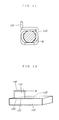
- the above-mentioned corner 132 may be formed, as shown in Fig. 2, so that the circumferential edge draws an arc when seen in the thickness direction, or the circumferential edge shows an inclined straight line.
- the circumferential edges of the face of the terminal 100 facing frontward in the depth direction may be formed so that the contour of the section thereof when sectioned in a plane facing the width direction or a plane facing the thickness direction have inclined straight lines or draw arcs.
- the 240 denotes a fitting member, and this fitting member 240 is located in such a position that the fitting member 240 does not interfere with the inside of the receiving cell 210 when the terminal 100 is inserted into the housing 200 or is withdrawn from the housing 200.
- the fitting member 240 When the terminal 100 is inserted into a predetermined position inside the housing 200, the fitting member 240 will be pushed in the width direction and in turn will be slid in the width direction, and as shown in Fig. 7, will be fitted on the rear side in the depth direction of the body 110 of the terminal 100, and this in turn will fit the terminal 100 on the housing 200.
- the terminal of the present invention includes embodiments wherein such a fitting member 240 is not provided.
- the strength of the terminal 100 is secured by this arrangement.
- the joining part of the body 110 is provided by overlapping the inner plate 114 and the outer plate 115 each other, even if the body 110 is subjected to an external force, the external force will be dispersed to both the inner plate 114 and the outer plate 115, and they will bear the external force jointly. Hence the strength is enhanced.
- the configuration of the laid-down protruding piece is not limited. It may be a flat plate or a bent plate, or the laid-down protruding piece may contact the outer plate or it may not contact the outer place.
- the laid-down protruding piece 130's part opposing to the outer plate 115 is provided with a protruding part 134 that protrudes in the thickness direction and contacts the outer plate 115.
- the present invention includes embodiments wherein features of the embodiments described above are combined.
Landscapes
- Connector Housings Or Holding Contact Members (AREA)
Abstract
Description
Claims (7)
- A terminal (100) comprising
when a depth direction, a width direction and a thickness direction all being perpendicular to each other are assumed, a rectangular-tube-shaped body (110) having an opening (116) or a tab (117) at the front in the depth direction thereof and having a cross plate (111), a first vertical plate (112) and a second vertical plate (113) bending from both ends in the width direction of the cross plate (111) and rising to one side in the thickness direction, an inner plate (114) bending from the first vertical plate (112) and extending in the width direction close to the second vertical plate (113), and an outer plate (115) bending from the second vertical plate (113) and extending in the width direction close to the first vertical plate (112) to overlap with the inner plate (114),
a connecting part (120) extending from the body (110) rearward in the depth direction and to be connected to a conductor (W), and
a laid-down protruding piece (130) bending from the end in the width direction of the outer plate (115) of the body (110) to reverse in the width direction, extending in the width direction and having a width equal to or narrower than the width of the outer plate (115). - The terminal (100) as recited in claim 1,
wherein the laid-down protruding piece's part (131) bending from the end in the width direction of the outer plate (115) to reverse in the width direction is formed to draw an arc when seen in the depth direction. - The terminal (100) as recited in claim 1 or claim 2,
wherein the laid-down protruding piece's part opposing to the outer plate (115) is provided with a protruding part (134) that protrudes in the thickness direction and contact the outer plate (115). - The terminal (100) as recited in claim 3,
wherein the protruding part (134) is provided up to the rear end in the depth direction of the laid-down protruding piece (130). - The terminal (100) as recited in any of the claims 1 to 4,
wherein the corner (132) at the front in the depth direction and at the top end in the width direction of the laid-down protruding piece (130) is chamfered when seen in the thickness direction. - The terminal (100) as recited in any of the claims 1 to 5,
wherein the circumferential edges of the face of the terminal facing frontward in the depth direction are chamfered. - The terminal (100) as recited in claim 5 or claim 6,
wherein chamfer is R-chamfer that is formed by like drawing an arc.
Applications Claiming Priority (2)
| Application Number | Priority Date | Filing Date | Title |
|---|---|---|---|
| JP2003110920 | 2003-04-15 | ||
| JP2003110920 | 2003-04-15 |
Publications (3)
| Publication Number | Publication Date |
|---|---|
| EP1469561A2 true EP1469561A2 (en) | 2004-10-20 |
| EP1469561A3 EP1469561A3 (en) | 2005-02-09 |
| EP1469561B1 EP1469561B1 (en) | 2008-03-26 |
Family
ID=32906024
Family Applications (1)
| Application Number | Title | Priority Date | Filing Date |
|---|---|---|---|
| EP04008871A Expired - Lifetime EP1469561B1 (en) | 2003-04-15 | 2004-04-14 | Terminal |
Country Status (3)
| Country | Link |
|---|---|
| US (1) | US6905376B2 (en) |
| EP (1) | EP1469561B1 (en) |
| DE (1) | DE602004012645T2 (en) |
Cited By (2)
| Publication number | Priority date | Publication date | Assignee | Title |
|---|---|---|---|---|
| EP2086062A1 (en) * | 2008-01-25 | 2009-08-05 | Sumitomo Wiring Systems, Ltd. | Terminals, A terminal connecting structure and a connecting method |
| USD858443S1 (en) * | 2018-01-29 | 2019-09-03 | Tarng Yu Enterprise Co., Ltd. | Connector terminal |
Families Citing this family (30)
| Publication number | Priority date | Publication date | Assignee | Title |
|---|---|---|---|---|
| US7241185B1 (en) * | 2005-12-22 | 2007-07-10 | Tensolite Company | Integral bonding attachment |
| US7896712B2 (en) * | 2005-12-22 | 2011-03-01 | Tensolite, Llc | Integral bonding attachment |
| JP4499114B2 (en) * | 2007-01-25 | 2010-07-07 | タイコエレクトロニクスジャパン合同会社 | Terminal crimping method, terminal crimping apparatus, terminal crimping structure, and electrical connector |
| US7419410B2 (en) * | 2007-02-02 | 2008-09-02 | Tyco Electronics Corporation | Sealed orientation feature for a terminal |
| JP4465537B2 (en) * | 2007-06-14 | 2010-05-19 | Smc株式会社 | solenoid valve |
| DE102007040937B3 (en) * | 2007-08-30 | 2009-01-15 | Tyco Electronics Amp Gmbh | Electric contact |
| JP5396310B2 (en) * | 2010-03-01 | 2014-01-22 | 住友電装株式会社 | connector |
| JP5700811B2 (en) * | 2011-03-30 | 2015-04-15 | 矢崎総業株式会社 | connector |
| JP5699029B2 (en) * | 2011-04-28 | 2015-04-08 | 日本航空電子工業株式会社 | connector |
| US8911253B2 (en) * | 2011-06-13 | 2014-12-16 | Tyco Electronics Corporation | Receptacle contact |
| EP2642598B1 (en) * | 2012-03-19 | 2017-09-13 | Yazaki Europe Ltd | Electric terminal |
| US20140021193A1 (en) * | 2012-07-17 | 2014-01-23 | Shu-Chien Chao | Heating module |
| WO2014125963A1 (en) * | 2013-02-12 | 2014-08-21 | 矢崎総業株式会社 | Connector |
| US20150275952A1 (en) * | 2014-03-25 | 2015-10-01 | Fritz Stepper Gmbh & Co. Kg | Plug-on part for a plug connector |
| JP6527633B2 (en) * | 2015-07-23 | 2019-06-05 | モレックス エルエルシー | Terminal bracket |
| JP6341225B2 (en) * | 2016-04-27 | 2018-06-13 | 第一精工株式会社 | Terminals and connectors |
| DE112018001099T5 (en) * | 2017-03-01 | 2019-12-19 | Molex, Llc | Electrical connection and connector arrangement |
| JP7054432B2 (en) * | 2017-07-12 | 2022-04-14 | 株式会社オートネットワーク技術研究所 | Male terminal fittings and female terminal fittings |
| WO2019111320A1 (en) * | 2017-12-05 | 2019-06-13 | 住友電装株式会社 | Terminal |
| US10553963B1 (en) * | 2018-09-19 | 2020-02-04 | Te Connectivity Corporation | Insulation crimp with lead-in projection |
| JP7005117B2 (en) * | 2019-05-29 | 2022-01-21 | 矢崎総業株式会社 | Wires with terminals and wire harnesses |
| CN112350092B (en) * | 2019-08-08 | 2023-07-18 | 上海莫仕连接器有限公司 | Connector and terminal |
| JP2021089834A (en) * | 2019-12-04 | 2021-06-10 | 住友電装株式会社 | Terminal fitting |
| JP7073429B2 (en) * | 2020-03-18 | 2022-05-23 | 矢崎総業株式会社 | Manufacturing method of electric wire with terminal and electric wire with terminal |
| JP2021157972A (en) * | 2020-03-27 | 2021-10-07 | 住友電装株式会社 | Terminal fitting |
| JP7435329B2 (en) * | 2020-07-14 | 2024-02-21 | 住友電装株式会社 | terminal fittings |
| JP7435362B2 (en) * | 2020-08-25 | 2024-02-21 | 住友電装株式会社 | Terminal fittings and chain terminals |
| US12451635B2 (en) * | 2021-06-11 | 2025-10-21 | J.S.T. Corporation | Electrical female terminal |
| US11699869B2 (en) | 2021-06-11 | 2023-07-11 | J.S.T. Corporation | Electrical female terminal |
| USD1108376S1 (en) * | 2023-12-14 | 2026-01-06 | J.S.T. Corporation | Electrical female terminal |
Family Cites Families (13)
| Publication number | Priority date | Publication date | Assignee | Title |
|---|---|---|---|---|
| JPH039256A (en) | 1989-06-05 | 1991-01-17 | Showa Electric Wire & Cable Co Ltd | Water leak detector |
| JP3119418B2 (en) | 1994-04-20 | 2000-12-18 | 矢崎総業株式会社 | Terminal for waterproof connector |
| DE19705509C2 (en) | 1997-02-13 | 1999-04-29 | Siemens Ag | One-piece contact spring |
| JP3272263B2 (en) * | 1997-04-18 | 2002-04-08 | タイコエレクトロニクスアンプ株式会社 | Connector with terminal runout prevention mechanism |
| JP3936465B2 (en) | 1998-03-27 | 2007-06-27 | 矢崎総業株式会社 | Terminal |
| JP3224369B2 (en) * | 1998-07-16 | 2001-10-29 | 日本圧着端子製造株式会社 | Connector terminals and housing |
| JP2000091022A (en) | 1998-09-10 | 2000-03-31 | Harness Syst Tech Res Ltd | Waterproof connector |
| JP3544133B2 (en) | 1999-01-20 | 2004-07-21 | 住友電装株式会社 | Female terminal fitting |
| JP4030673B2 (en) | 1999-02-10 | 2008-01-09 | 日本圧着端子製造株式会社 | Female terminal of electrical connector |
| JP3480693B2 (en) | 1999-03-16 | 2003-12-22 | 住友電装株式会社 | Female terminal fitting |
| JP3544155B2 (en) * | 1999-10-22 | 2004-07-21 | 住友電装株式会社 | Terminal fitting |
| JP2002050416A (en) | 2000-08-07 | 2002-02-15 | Sumitomo Wiring Syst Ltd | Metal fitting for pressure welding |
| DE60216679T2 (en) * | 2001-08-30 | 2007-10-04 | Tyco Electronics Amp Gmbh | Contact with improved locking element |
-
2004
- 2004-04-13 US US10/823,909 patent/US6905376B2/en not_active Expired - Lifetime
- 2004-04-14 EP EP04008871A patent/EP1469561B1/en not_active Expired - Lifetime
- 2004-04-14 DE DE602004012645T patent/DE602004012645T2/en not_active Expired - Lifetime
Cited By (2)
| Publication number | Priority date | Publication date | Assignee | Title |
|---|---|---|---|---|
| EP2086062A1 (en) * | 2008-01-25 | 2009-08-05 | Sumitomo Wiring Systems, Ltd. | Terminals, A terminal connecting structure and a connecting method |
| USD858443S1 (en) * | 2018-01-29 | 2019-09-03 | Tarng Yu Enterprise Co., Ltd. | Connector terminal |
Also Published As
| Publication number | Publication date |
|---|---|
| US20040209527A1 (en) | 2004-10-21 |
| DE602004012645T2 (en) | 2009-06-18 |
| EP1469561A3 (en) | 2005-02-09 |
| EP1469561B1 (en) | 2008-03-26 |
| US6905376B2 (en) | 2005-06-14 |
| DE602004012645D1 (en) | 2008-05-08 |
Similar Documents
| Publication | Publication Date | Title |
|---|---|---|
| US6905376B2 (en) | Terminal | |
| US8333622B2 (en) | Dual contact beam terminal | |
| EP1351338B1 (en) | A terminal fitting | |
| US7938695B2 (en) | Terminal fitting | |
| US6244910B1 (en) | Electrical box contact with stress limitation | |
| US7144281B2 (en) | Female terminal fitting and a blank for a plurality of terminal fittings | |
| US8708759B2 (en) | Terminal fitting and connector | |
| JP2008282807A (en) | Electrical contact | |
| US20030228795A1 (en) | Connector, a disengagement jig and a method | |
| US6733346B2 (en) | Terminal fitting, a connector provided therewith and a method for forming a terminal fitting | |
| JPH09147948A (en) | Electric terminal and electric connector using the same | |
| US5645458A (en) | Electrical receptacle terminal | |
| US6729904B2 (en) | Terminal fitting and a connector provided therewith | |
| EP1369963B1 (en) | A connector and a method for inserting a terminal fitting thereinto | |
| JP3745634B2 (en) | Terminal fitting | |
| US6290554B1 (en) | Female terminal fitting and a female connector | |
| EP1376768A1 (en) | An electrical connector | |
| US6033262A (en) | Contact spring | |
| EP1391970B1 (en) | A connector | |
| US11245213B2 (en) | Clean body electric terminal | |
| US6283803B1 (en) | Electrical contact | |
| US6428366B1 (en) | Electrical terminal socket and method of fabricating same | |
| CN112909608B (en) | Terminal fitting | |
| EP1863133B1 (en) | A male terminal fitting, a plate material therefor and a method of forming it | |
| EP1911129B1 (en) | Male electrical terminal |
Legal Events
| Date | Code | Title | Description |
|---|---|---|---|
| PUAI | Public reference made under article 153(3) epc to a published international application that has entered the european phase |
Free format text: ORIGINAL CODE: 0009012 |
|
| AK | Designated contracting states |
Kind code of ref document: A2 Designated state(s): AT BE BG CH CY CZ DE DK EE ES FI FR GB GR HU IE IT LI LU MC NL PL PT RO SE SI SK TR |
|
| AX | Request for extension of the european patent |
Extension state: AL HR LT LV MK |
|
| PUAL | Search report despatched |
Free format text: ORIGINAL CODE: 0009013 |
|
| AK | Designated contracting states |
Kind code of ref document: A3 Designated state(s): AT BE BG CH CY CZ DE DK EE ES FI FR GB GR HU IE IT LI LU MC NL PL PT RO SE SI SK TR |
|
| AX | Request for extension of the european patent |
Extension state: AL HR LT LV MK |
|
| RIC1 | Information provided on ipc code assigned before grant |
Ipc: 7H 01R 13/422 A Ipc: 7H 01R 13/115 B |
|
| 17P | Request for examination filed |
Effective date: 20050715 |
|
| AKX | Designation fees paid |
Designated state(s): DE FR GB |
|
| GRAP | Despatch of communication of intention to grant a patent |
Free format text: ORIGINAL CODE: EPIDOSNIGR1 |
|
| GRAS | Grant fee paid |
Free format text: ORIGINAL CODE: EPIDOSNIGR3 |
|
| GRAA | (expected) grant |
Free format text: ORIGINAL CODE: 0009210 |
|
| AK | Designated contracting states |
Kind code of ref document: B1 Designated state(s): DE FR GB |
|
| REG | Reference to a national code |
Ref country code: GB Ref legal event code: FG4D |
|
| REF | Corresponds to: |
Ref document number: 602004012645 Country of ref document: DE Date of ref document: 20080508 Kind code of ref document: P |
|
| ET | Fr: translation filed | ||
| PLBE | No opposition filed within time limit |
Free format text: ORIGINAL CODE: 0009261 |
|
| STAA | Information on the status of an ep patent application or granted ep patent |
Free format text: STATUS: NO OPPOSITION FILED WITHIN TIME LIMIT |
|
| 26N | No opposition filed |
Effective date: 20081230 |
|
| PGFP | Annual fee paid to national office [announced via postgrant information from national office to epo] |
Ref country code: DE Payment date: 20130424 Year of fee payment: 10 Ref country code: GB Payment date: 20130422 Year of fee payment: 10 |
|
| PGFP | Annual fee paid to national office [announced via postgrant information from national office to epo] |
Ref country code: FR Payment date: 20130523 Year of fee payment: 10 |
|
| REG | Reference to a national code |
Ref country code: DE Ref legal event code: R119 Ref document number: 602004012645 Country of ref document: DE |
|
| GBPC | Gb: european patent ceased through non-payment of renewal fee |
Effective date: 20140414 |
|
| REG | Reference to a national code |
Ref country code: FR Ref legal event code: ST Effective date: 20141231 |
|
| REG | Reference to a national code |
Ref country code: DE Ref legal event code: R119 Ref document number: 602004012645 Country of ref document: DE Effective date: 20141101 |
|
| PG25 | Lapsed in a contracting state [announced via postgrant information from national office to epo] |
Ref country code: GB Free format text: LAPSE BECAUSE OF NON-PAYMENT OF DUE FEES Effective date: 20140414 Ref country code: DE Free format text: LAPSE BECAUSE OF NON-PAYMENT OF DUE FEES Effective date: 20141101 |
|
| PG25 | Lapsed in a contracting state [announced via postgrant information from national office to epo] |
Ref country code: FR Free format text: LAPSE BECAUSE OF NON-PAYMENT OF DUE FEES Effective date: 20140430 |