EP1469307A2 - Coating inspection - Google Patents
Coating inspection Download PDFInfo
- Publication number
- EP1469307A2 EP1469307A2 EP04252268A EP04252268A EP1469307A2 EP 1469307 A2 EP1469307 A2 EP 1469307A2 EP 04252268 A EP04252268 A EP 04252268A EP 04252268 A EP04252268 A EP 04252268A EP 1469307 A2 EP1469307 A2 EP 1469307A2
- Authority
- EP
- European Patent Office
- Prior art keywords
- turbine engine
- gas turbine
- coating
- electrode
- layer
- Prior art date
- Legal status (The legal status is an assumption and is not a legal conclusion. Google has not performed a legal analysis and makes no representation as to the accuracy of the status listed.)
- Withdrawn
Links
- 238000000576 coating method Methods 0.000 title claims abstract description 35
- 239000011248 coating agent Substances 0.000 title claims abstract description 31
- 238000007689 inspection Methods 0.000 title description 10
- 238000000034 method Methods 0.000 claims abstract description 26
- 239000000758 substrate Substances 0.000 claims abstract description 16
- 238000012360 testing method Methods 0.000 claims description 11
- 239000000919 ceramic Substances 0.000 claims description 8
- 238000002847 impedance measurement Methods 0.000 claims description 2
- 239000007788 liquid Substances 0.000 claims 5
- 230000008878 coupling Effects 0.000 claims 3
- 238000010168 coupling process Methods 0.000 claims 3
- 238000005859 coupling reaction Methods 0.000 claims 3
- 239000011800 void material Substances 0.000 claims 2
- 239000010410 layer Substances 0.000 description 10
- 238000009736 wetting Methods 0.000 description 6
- 239000003792 electrolyte Substances 0.000 description 5
- 230000007547 defect Effects 0.000 description 4
- 238000009658 destructive testing Methods 0.000 description 4
- 238000004458 analytical method Methods 0.000 description 3
- 230000032798 delamination Effects 0.000 description 3
- 238000011065 in-situ storage Methods 0.000 description 3
- 238000000926 separation method Methods 0.000 description 3
- 229910000601 superalloy Inorganic materials 0.000 description 3
- 239000012720 thermal barrier coating Substances 0.000 description 3
- MCMNRKCIXSYSNV-UHFFFAOYSA-N Zirconium dioxide Chemical compound O=[Zr]=O MCMNRKCIXSYSNV-UHFFFAOYSA-N 0.000 description 2
- 229910045601 alloy Inorganic materials 0.000 description 2
- 239000000956 alloy Substances 0.000 description 2
- 238000005328 electron beam physical vapour deposition Methods 0.000 description 2
- 229910000951 Aluminide Inorganic materials 0.000 description 1
- PNEYBMLMFCGWSK-UHFFFAOYSA-N aluminium oxide Inorganic materials [O-2].[O-2].[O-2].[Al+3].[Al+3] PNEYBMLMFCGWSK-UHFFFAOYSA-N 0.000 description 1
- 230000015556 catabolic process Effects 0.000 description 1
- 239000008199 coating composition Substances 0.000 description 1
- 239000011247 coating layer Substances 0.000 description 1
- 229910017052 cobalt Inorganic materials 0.000 description 1
- 239000010941 cobalt Substances 0.000 description 1
- GUTLYIVDDKVIGB-UHFFFAOYSA-N cobalt atom Chemical compound [Co] GUTLYIVDDKVIGB-UHFFFAOYSA-N 0.000 description 1
- 238000004891 communication Methods 0.000 description 1
- 239000004020 conductor Substances 0.000 description 1
- 238000006731 degradation reaction Methods 0.000 description 1
- 238000000151 deposition Methods 0.000 description 1
- 230000008021 deposition Effects 0.000 description 1
- 238000009792 diffusion process Methods 0.000 description 1
- 239000008151 electrolyte solution Substances 0.000 description 1
- 230000007613 environmental effect Effects 0.000 description 1
- 238000011156 evaluation Methods 0.000 description 1
- 239000012530 fluid Substances 0.000 description 1
- 230000006872 improvement Effects 0.000 description 1
- 238000012986 modification Methods 0.000 description 1
- 230000004048 modification Effects 0.000 description 1
- 230000000737 periodic effect Effects 0.000 description 1
- 238000005240 physical vapour deposition Methods 0.000 description 1
- 239000010979 ruby Substances 0.000 description 1
- 229910001750 ruby Inorganic materials 0.000 description 1
- 239000000523 sample Substances 0.000 description 1
- 238000005070 sampling Methods 0.000 description 1
- 238000001878 scanning electron micrograph Methods 0.000 description 1
- 238000009718 spray deposition Methods 0.000 description 1
- 230000007704 transition Effects 0.000 description 1
- 230000000007 visual effect Effects 0.000 description 1
- RUDFQVOCFDJEEF-UHFFFAOYSA-N yttrium(III) oxide Inorganic materials [O-2].[O-2].[O-2].[Y+3].[Y+3] RUDFQVOCFDJEEF-UHFFFAOYSA-N 0.000 description 1
Images


Classifications
-
- G—PHYSICS
- G01—MEASURING; TESTING
- G01N—INVESTIGATING OR ANALYSING MATERIALS BY DETERMINING THEIR CHEMICAL OR PHYSICAL PROPERTIES
- G01N27/00—Investigating or analysing materials by the use of electric, electrochemical, or magnetic means
- G01N27/72—Investigating or analysing materials by the use of electric, electrochemical, or magnetic means by investigating magnetic variables
- G01N27/82—Investigating or analysing materials by the use of electric, electrochemical, or magnetic means by investigating magnetic variables for investigating the presence of flaws
Definitions
- This invention relates to inspection of thermal barrier coatings, and more particularly to inspection of coatings on turbine components.
- Gas turbine engine components e.g., blades, vanes, seals, combustor panels, and the like
- TBCs Thermal barrier coatings
- Various coating compositions e.g., ceramics
- various coating methods e.g., electron beam physical vapor deposition (EBPVD) and plasma spray deposition
- An exemplary modern coating system is applied to the superalloy substrate by an EB-PVD technique.
- An exemplary coating system includes a metallic bondcoat layer (e.g., an overlay of NiCoCrAlY alloy or diffusion aluminide) atop the substrate.
- a thermally insulating ceramic top coat layer e.g., zirconia stabilized with yttria
- a thermally grown oxide layer e.g., alumina, forms on the bondcoat and intervenes between the remaining underlying portion of the bondcoat and the top coat.
- the coatings are subject to potential defects.
- the TGO to bondcoat interface tends to suffer from separations/delaminations.
- Such defects tend to be inherent, so threshold degrees of defect may determine the utility of a given component. Defects may also form during use.
- Much of existing inspection involves destructive testing used to approve or reject batches of components.
- Exemplary destructive testing involves epoxy-mounting and sectioning a component followed by microscopic examination.
- the TGO is a critical element. This may be viewed via scanning electron microscope (SEM) at 1,000x or higher. Quality standards are used to approve or reject the batch based upon visual interpretation of the SEM images.
- SEM scanning electron microscope
- Destructive testing suffers from many general drawbacks as do its various particular techniques.
- the former includes the cost of destroyed components, the inaccuracy inherent in batch sampling, and the cost of time.
- U.S. patent 6,352,406 discloses an alternate system involving coating of a pre-couponed turbine blade facsimile in lieu of cutting an actual blade. This may slightly reduce the time spent, but does not address the fundamental problems of destructive testing.
- Laser fluorescence has been used for nondestructive evaluation of limited coating parameters.
- the beam of a ruby laser is shined on the ceramic top coat and passes therethrough to reach the TGO.
- the TGO fluoresces and the emitted light passes through the top coat to a sensor.
- Characteristics of the flurorecence indicate stress in the TGO. Separation/delamination voids are associated with reduced stress and can thus be detected.
- U.S. patent 6,072,568 discloses such inspection.
- one aspect of the invention is a method for inspecting a multi-layer coating on a substrate of a turbine element airfoil. At each of a number of locations along the airfoil, a number of frequencies of alternating current are passed through the airfoil. At least one impedance parameter is measured. Based upon the measured impedance parameters, a condition of the coating is determined.
- the current may pass through an electrolyte wetting the airfoil.
- the method may determine thicknesses of one or more layers of the coating and may identify or characterize voids within the coating or between the substrate and the coating.
- the method may advantageously be performed in situ with the turbine element installed on a turbo-machine.
- the method may be performed seriatim on a number of turbine elements on the turbo-machine.
- the apparatus may have a source of the current and electrodes for passing the current through the airfoil.
- the apparatus may have means for measuring the impedance parameter and means for determining the coating condition.
- FIG. 1 shows an apparatus 20 for testing/inspecting a coated item such as a turbine element (e.g., a turbine engine blade 22).
- the exemplary blade 22 includes an airfoil 24 extending from a root 26 at a platform 28 to a tip 30.
- the airfoil has leading and trailing edges 32 and 34 separating pressure and suction sides 36 and 38.
- the platform has an outboard portion 40 for forming an inboard boundary/wall of a core flowpath through the turbine engine.
- a mounting portion or blade root 42 depends centrally from the underside of the platform 40 for fixing the blade in a disk of the turbine engine.
- the portion 40 and airfoil 24 are coated.
- the exemplary system 20 includes an impedance analyzer 50 coupled by conductors 51 and 52 to a pair of electrodes 53 and 54.
- the first electrode 53 may be a standard reference electrode contacted with an uncoated portion of the platform.
- the second electrode 54 is contacted with a coated portion of the blade and, therefore, is advantageously provided as a wetting electrode.
- the wetting electrode 54 includes a standard reference electrode 56 mounted in a proximal end of a tubular vessel 58 and contacting an electrolyte 60 within the vessel.
- a check valve 62 is mounted in a distal end of the vessel 58.
- the check valve 62 When the check valve 62 is contacted with the coating, it establishes fluid communication between the contact site and the interior of the vessel providing a small wetting of the coated surface with the electrolyte and providing an electrical path through the electrolyte from the coating to the reference electrode 56.
- FIG. 2 shows further details of the coating 70 on a metallic substrate 72 of the blade.
- the blade has an outer surface 74 atop which the coating layers are deposited.
- the layers include a metallic bondcoat 76 atop the substrate surface 74, an in situ formed TGO layer 78 atop the bondcoat, and a ceramic topcoat 80 atop the TGO and having an external surface 82.
- Contact is made between the electrode 54 and the surface 82 via the wetting electrolyte 84. Direct electrical contact is made between the electrode 53 and an exposed uncoated surface 86 of the substrate.
- the system 20 of FIG. 1. may include an environmental control chamber 100 (FIG. 3) for containing the blade 22 during testing and that controls various properties of temperature, humidity, pressure, and the like.
- the current is provided by a current amplifier 102 coupled to an impedance analyzer 104 for measuring impedance parameters.
- the impedance analyzer 104 is coupled to analysis equipment such as a computer 106.
- the computer may display results of the measured parameters and perform analyses to determine quantitative and qualitative properties of the coating based on the received parameters.
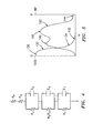
- FIG. 4 shows a basic electric circuit model. From one end of the circuit to the other, the resistance of the electrode 54 (FIG. 1) is shown as R P in series with an electrolyte solution resistance R S . This, in turn, is in series with the parallel combination of a topcoat resistance R C and a topcoat capacitance C C . This, in turn, is in series with the parallel combination of a TGO resistance R O multiplied by a Warburg coefficient W O and a TGO capacitance C O . This is, in turn, in series with the parallel combination of a resistance R T of the interface between the superalloy and bondcoat and an interface capacitance C T .
- FIG. 5 shows an exemplary graph 120 of impedance Q against frequency ⁇ .
- An exemplary impedance scale is 0-1500 Kohm/cm 2 .
- FIG. 5 further shows an exemplary graph 122 of phase angle ⁇ against frequency.
- An exemplary phase angle scale is 0 to 80°.
- roughly the location of the impedance peak 130 is indicative of R T .
- the location of the impedance tail 132 is indicative of R P .
- In the location of the transition 134 is indicative of R C and R O .
- the location of a low frequency phase angle peak 140 is indicative of C O and the location of a high frequency phase angle peak 142 is indicative of C C .
- the location of a tail 144 is indicative of C T .
- the wetting electrode may be moved seriatim to a plurality of positions on the blade and impedance measurements taken. Analysis of data from such multiple positions may be used to even better determine coating properties.
Landscapes
- Chemical & Material Sciences (AREA)
- Chemical Kinetics & Catalysis (AREA)
- Electrochemistry (AREA)
- Physics & Mathematics (AREA)
- Health & Medical Sciences (AREA)
- Life Sciences & Earth Sciences (AREA)
- Analytical Chemistry (AREA)
- Biochemistry (AREA)
- General Health & Medical Sciences (AREA)
- General Physics & Mathematics (AREA)
- Immunology (AREA)
- Pathology (AREA)
- Investigating Or Analyzing Materials By The Use Of Electric Means (AREA)
- Turbine Rotor Nozzle Sealing (AREA)
Abstract
Description
- This invention relates to inspection of thermal barrier coatings, and more particularly to inspection of coatings on turbine components.
- Gas turbine engine components (e.g., blades, vanes, seals, combustor panels, and the like) are commonly formed of nickel- or cobalt-based superalloys. Desired operating temperatures often exceed that possible for the alloys alone. Thermal barrier coatings (TBCs) are in common use on such components to permit use at elevated temperatures. Various coating compositions (e.g., ceramics) and various coating methods (e.g., electron beam physical vapor deposition (EBPVD) and plasma spray deposition) are known.
- An exemplary modern coating system is applied to the superalloy substrate by an EB-PVD technique. An exemplary coating system includes a metallic bondcoat layer (e.g., an overlay of NiCoCrAlY alloy or diffusion aluminide) atop the substrate. A thermally insulating ceramic top coat layer (e.g., zirconia stabilized with yttria) is deposited atop the bondcoat. During this deposition, a thermally grown oxide layer (TGO), e.g., alumina, forms on the bondcoat and intervenes between the remaining underlying portion of the bondcoat and the top coat.
- The coatings are subject to potential defects. For example, the TGO to bondcoat interface tends to suffer from separations/delaminations. Such defects tend to be inherent, so threshold degrees of defect may determine the utility of a given component. Defects may also form during use.
- Much of existing inspection involves destructive testing used to approve or reject batches of components. Exemplary destructive testing involves epoxy-mounting and sectioning a component followed by microscopic examination. The TGO is a critical element. This may be viewed via scanning electron microscope (SEM) at 1,000x or higher. Quality standards are used to approve or reject the batch based upon visual interpretation of the SEM images.
- Destructive testing suffers from many general drawbacks as do its various particular techniques. The former includes the cost of destroyed components, the inaccuracy inherent in batch sampling, and the cost of time. U.S. patent 6,352,406 discloses an alternate system involving coating of a pre-couponed turbine blade facsimile in lieu of cutting an actual blade. This may slightly reduce the time spent, but does not address the fundamental problems of destructive testing.
- Laser fluorescence has been used for nondestructive evaluation of limited coating parameters. In one example, the beam of a ruby laser is shined on the ceramic top coat and passes therethrough to reach the TGO. The TGO fluoresces and the emitted light passes through the top coat to a sensor. Characteristics of the flurorecence indicate stress in the TGO. Separation/delamination voids are associated with reduced stress and can thus be detected. U.S. patent 6,072,568 discloses such inspection.
- There remains a substantial need for improvement in testing techniques.
- Accordingly, one aspect of the invention is a method for inspecting a multi-layer coating on a substrate of a turbine element airfoil. At each of a number of locations along the airfoil, a number of frequencies of alternating current are passed through the airfoil. At least one impedance parameter is measured. Based upon the measured impedance parameters, a condition of the coating is determined.
- The current may pass through an electrolyte wetting the airfoil. The method may determine thicknesses of one or more layers of the coating and may identify or characterize voids within the coating or between the substrate and the coating. The method may advantageously be performed in situ with the turbine element installed on a turbo-machine. The method may be performed seriatim on a number of turbine elements on the turbo-machine.
- Another aspect of the invention is an inspection apparatus. The apparatus may have a source of the current and electrodes for passing the current through the airfoil. The apparatus may have means for measuring the impedance parameter and means for determining the coating condition.
- The details of one or more embodiments of the invention are set forth in the accompanying drawings and the description below. Other features, objects, and advantages of the invention will be apparent from the description and drawings, and from the claims.
-
- FIG. 1 is a view of a coating test/inspection system.
- FIG. 2 is a sectional view of a coated item.
- FIG. 3 is an alternate view of a test/inspection system.
- FIG. 4 is a circuit equivalent model of a coating.
- FIG. 5 is a graph of impedance and phase angle against frequency for an exemplary coating.
-
- Like reference numbers and designations in the various drawings indicate like elements.
- FIG. 1 shows an
apparatus 20 for testing/inspecting a coated item such as a turbine element (e.g., a turbine engine blade 22). Theexemplary blade 22 includes anairfoil 24 extending from aroot 26 at aplatform 28 to atip 30. The airfoil has leading and trailingedges suction sides outboard portion 40 for forming an inboard boundary/wall of a core flowpath through the turbine engine. A mounting portion orblade root 42 depends centrally from the underside of theplatform 40 for fixing the blade in a disk of the turbine engine. In an exemplary embodiment, theportion 40 andairfoil 24 are coated. - The
exemplary system 20 includes animpedance analyzer 50 coupled byconductors electrodes first electrode 53 may be a standard reference electrode contacted with an uncoated portion of the platform. Thesecond electrode 54 is contacted with a coated portion of the blade and, therefore, is advantageously provided as a wetting electrode. Thewetting electrode 54 includes astandard reference electrode 56 mounted in a proximal end of atubular vessel 58 and contacting anelectrolyte 60 within the vessel. Acheck valve 62 is mounted in a distal end of thevessel 58. When thecheck valve 62 is contacted with the coating, it establishes fluid communication between the contact site and the interior of the vessel providing a small wetting of the coated surface with the electrolyte and providing an electrical path through the electrolyte from the coating to thereference electrode 56. - FIG. 2 shows further details of the
coating 70 on ametallic substrate 72 of the blade. The blade has an outer surface 74 atop which the coating layers are deposited. The layers include ametallic bondcoat 76 atop the substrate surface 74, an in situ formedTGO layer 78 atop the bondcoat, and aceramic topcoat 80 atop the TGO and having anexternal surface 82. Contact is made between theelectrode 54 and thesurface 82 via the wettingelectrolyte 84. Direct electrical contact is made between theelectrode 53 and an exposeduncoated surface 86 of the substrate. - In a laboratory setting, the
system 20 of FIG. 1. may include an environmental control chamber 100 (FIG. 3) for containing theblade 22 during testing and that controls various properties of temperature, humidity, pressure, and the like. The current is provided by acurrent amplifier 102 coupled to animpedance analyzer 104 for measuring impedance parameters. Theimpedance analyzer 104 is coupled to analysis equipment such as acomputer 106. The computer may display results of the measured parameters and perform analyses to determine quantitative and qualitative properties of the coating based on the received parameters. - Various theoretical, empirical or hybrid models may be used to determine coating properties. Such properties may include the layer thicknesses and the presence, size, and quantity of imperfections (e.g., voids within layers or between layers (e.g., separations and delaminations)). FIG. 4 shows a basic electric circuit model. From one end of the circuit to the other, the resistance of the electrode 54 (FIG. 1) is shown as RP in series with an electrolyte solution resistance RS. This, in turn, is in series with the parallel combination of a topcoat resistance RC and a topcoat capacitance CC. This, in turn, is in series with the parallel combination of a TGO resistance RO multiplied by a Warburg coefficient WO and a TGO capacitance CO. This is, in turn, in series with the parallel combination of a resistance RT of the interface between the superalloy and bondcoat and an interface capacitance CT.
- FIG. 5 shows an
exemplary graph 120 of impedance Q against frequency ω. An exemplary impedance scale is 0-1500 Kohm/cm2. FIG. 5 further shows anexemplary graph 122 of phase angle against frequency. An exemplary phase angle scale is 0 to 80°. In this model, roughly the location of theimpedance peak 130 is indicative of RT. The location of theimpedance tail 132 is indicative of RP. In the location of thetransition 134 is indicative of RC and RO. The location of a low frequencyphase angle peak 140 is indicative of CO and the location of a high frequencyphase angle peak 142 is indicative of CC. The location of atail 144 is indicative of CT. The wetting electrode may be moved seriatim to a plurality of positions on the blade and impedance measurements taken. Analysis of data from such multiple positions may be used to even better determine coating properties. - Less environmentally controlled tests may be performed in situ on an assembled engine such as performing periodic tests on an aircraft engine. Such testing may be used to determine wear and other degradation parameters and determine remaining life of the turbine element. Alternative tests may involve contacting two probes with the coating. This may be appropriate where convenient access to uncoated portions is difficult. Relatively complex models could be used for such a situation.
- One or more embodiments of the present invention have been described. Nevertheless, it will be understood that various modifications may be made without departing from the spirit and scope of the invention. For example, details of the particular turbine elements, coatings, test conditions, and examination criteria may influence the structure of the inspection apparatus and implementation of the inspection methods. Accordingly, other embodiments are within the scope of the following claims.
Claims (16)
- A method for inspecting a multi-layer coating (70) on a substrate (72) of a gas turbine engine component (22), the method comprising:wherein said current is passed between first and second electrodes (54,53) and wherein an ionically conductive liquid (60) is applied at a contact point of at least the first electrode (54).for each of a plurality of frequencies of alternating current:passing said current through the component (22); andmeasuring at least one impedance parameter; anddetermining a condition of the coating,
- The method of claim 1 performed repeatedly for each of a plurality of locations along the component (22).
- The method of claim 2 wherein for each said location the current is passed between said first electrode (54) uniquely positioned relative to said location and said second electrode (53) commonly positioned.
- The method of claim 2 wherein for each said location the current is passed between said first electrode (54) uniquely positioned relative to said location and said second electrode (53) uniquely positioned relative to said location.
- The method of any preceding claim performed while the gas turbine engine component is installed on a gas turbine engine.
- The method of any preceding claim wherein said determining comprises determining a thickness of at least one layer of the coating.
- The method of any of claims 1 to 5 wherein said determining comprises identifying a void within the coating (70) or between the substrate (72) and the coating (70).
- The method of any preceding claim performed seriatim on a plurality of gas turbine engine components (22) on said gas turbine engine.
- The method of any preceding claim further comprising:approving or rejecting the gas turbine engine component (22) or;determining a remaining useful life of the gas turbine engine component.
- A method for inspecting a coated item (22) comprising:wherein said electrically coupling comprises applying ionically conductive liquid (60) at a contact location between the first electrode (54) and the coated item (22).electrically coupling first and second electrodes (54,53) of a test apparatus to the item;passing an alternating current between the electrodes, the current passing through at least:a ceramic layer (80);a metallic substrate (72);a bondcoat layer (76) between the ceramiclayer (80) and the metallic substrate (72); and
an additional layer (78) between the bondcoatlayer (76) and the ceramic layer (80); andmeasuring an impedance parameter, - The method of claim 10 wherein said electrically coupling comprises applying ionically conductive liquid (60) at a contact location between the second electrode (54) and the coated item (22).
- The method of claim 10 or 11 wherein said liquid (60) is applied prior to contacting the item (22) with the first electrode (54).
- The method of claim 10, 11 or 12 further comprising using said impedance parameter to determine a size characteristic of a void between an adjacent two of the substrate (72), the bondcoat layer (76), the additional layer (78), and the ceramic layer (80).
- A method for inspecting a multi-layer coating (70) on a substrate (72) of a gas turbine engine component (22) performed while the gas turbine engine component is installed on a gas turbine engine, the method comprising:for each of a plurality of locations along the component:for each of a plurality of frequencies of alternating current:passing said current through the component (22); andmeasuring at least one impedance parameter; anddetermining a condition of the coating (70).
- The method of claim 14 wherein the gas turbine engine element has an airfoil (122) and the plurality of locations are along the airfoil (22).
- Apparatus for inspecting a multi-layer coating (70) on a substrate (72) of a gas turbine engine component (22) comprising:a multifrequency a.c. supply;a pair of electrodes (53,54) connectable to said supply, one of said electrodes (54) having an ionically conductive liquid (60) associated therewith; andan impedance measurement device for measuring the impedance of a component arranged between said electrodes (53,54).
Applications Claiming Priority (2)
| Application Number | Priority Date | Filing Date | Title |
|---|---|---|---|
| US417032 | 2003-04-16 | ||
| US10/417,032 US6979991B2 (en) | 2003-04-16 | 2003-04-16 | Nondestructive, electrical impedance-based, thermal barrier coating inspection |
Publications (2)
| Publication Number | Publication Date |
|---|---|
| EP1469307A2 true EP1469307A2 (en) | 2004-10-20 |
| EP1469307A3 EP1469307A3 (en) | 2005-03-16 |
Family
ID=32908329
Family Applications (1)
| Application Number | Title | Priority Date | Filing Date |
|---|---|---|---|
| EP04252268A Withdrawn EP1469307A3 (en) | 2003-04-16 | 2004-04-16 | Coating inspection |
Country Status (3)
| Country | Link |
|---|---|
| US (1) | US6979991B2 (en) |
| EP (1) | EP1469307A3 (en) |
| SG (1) | SG115674A1 (en) |
Cited By (4)
| Publication number | Priority date | Publication date | Assignee | Title |
|---|---|---|---|---|
| EP1600765A1 (en) * | 2004-05-25 | 2005-11-30 | United Technologies Corporation | Probes for electrochemical impedance spectroscopy |
| WO2007001454A3 (en) * | 2004-12-20 | 2007-04-19 | Siemens Power Generation Inc | System for on-line assessment of the condition of a thermal coating on a turbine vane |
| GB2461272A (en) * | 2008-06-24 | 2009-12-30 | Emt Res As | Method and system for determining coating performance |
| EP2064536A4 (en) * | 2006-08-28 | 2012-05-30 | Detection Systems Pty Ltd | Production line detection apparatus and method |
Families Citing this family (22)
| Publication number | Priority date | Publication date | Assignee | Title |
|---|---|---|---|---|
| US6730918B2 (en) * | 2001-12-20 | 2004-05-04 | General Electric Company | Apparatus for determining past-service conditions and remaining life of thermal barrier coatings and components having such coatings |
| US8004423B2 (en) * | 2004-06-21 | 2011-08-23 | Siemens Energy, Inc. | Instrumented component for use in an operating environment |
| US7157920B2 (en) * | 2004-08-10 | 2007-01-02 | United Technologies Corporation | Non-destructive monitoring of material integrity |
| WO2007095573A2 (en) * | 2006-02-14 | 2007-08-23 | Ndsu Research Foundation | Electrochemical impedance spectroscopy method and system |
| GB0605907D0 (en) * | 2006-03-24 | 2006-05-03 | Rolls Royce Fuel Cell Systems | A Method Of Sintering Ceramic Materials |
| US20080039743A1 (en) | 2006-08-09 | 2008-02-14 | Coherex Medical, Inc. | Methods for determining characteristics of an internal tissue opening |
| US9138208B2 (en) | 2006-08-09 | 2015-09-22 | Coherex Medical, Inc. | Devices for reducing the size of an internal tissue opening |
| US8529597B2 (en) | 2006-08-09 | 2013-09-10 | Coherex Medical, Inc. | Devices for reducing the size of an internal tissue opening |
| US7368827B2 (en) * | 2006-09-06 | 2008-05-06 | Siemens Power Generation, Inc. | Electrical assembly for monitoring conditions in a combustion turbine operating environment |
| US7969323B2 (en) * | 2006-09-14 | 2011-06-28 | Siemens Energy, Inc. | Instrumented component for combustion turbine engine |
| US7918141B1 (en) * | 2007-04-03 | 2011-04-05 | The United States Of America As Represented By The Secretary Of The Air Force | Local residual stress measurement and analysis for detection and prediction of damage in thermal barrier coatings |
| US7750643B2 (en) * | 2007-10-30 | 2010-07-06 | General Electric Company | Process and system for detecting surface anomalies |
| US8519866B2 (en) | 2007-11-08 | 2013-08-27 | Siemens Energy, Inc. | Wireless telemetry for instrumented component |
| US8797179B2 (en) * | 2007-11-08 | 2014-08-05 | Siemens Aktiengesellschaft | Instrumented component for wireless telemetry |
| US9071888B2 (en) * | 2007-11-08 | 2015-06-30 | Siemens Aktiengesellschaft | Instrumented component for wireless telemetry |
| US20100161287A1 (en) * | 2008-12-22 | 2010-06-24 | Sauerhoefer Marc R | Measurement data management system |
| US20110086163A1 (en) | 2009-10-13 | 2011-04-14 | Walbar Inc. | Method for producing a crack-free abradable coating with enhanced adhesion |
| US20110086177A1 (en) | 2009-10-14 | 2011-04-14 | WALBAR INC. Peabody Industrial Center | Thermal spray method for producing vertically segmented thermal barrier coatings |
| US8636462B2 (en) * | 2011-01-10 | 2014-01-28 | General Electric Company | Methods, systems and apparatus for detecting material defects in rotor blades of combustion turbine engines |
| US9325388B2 (en) | 2012-06-21 | 2016-04-26 | Siemens Energy, Inc. | Wireless telemetry system including an induction power system |
| CN103076376B (en) * | 2013-01-08 | 2015-08-05 | 苏州热工研究院有限公司 | Metal and applying coating metal erosion state verification array electrode |
| US9420356B2 (en) | 2013-08-27 | 2016-08-16 | Siemens Energy, Inc. | Wireless power-receiving assembly for a telemetry system in a high-temperature environment of a combustion turbine engine |
Citations (3)
| Publication number | Priority date | Publication date | Assignee | Title |
|---|---|---|---|---|
| US4806849A (en) * | 1986-03-31 | 1989-02-21 | Nippon Steel Corporation | Method and apparatus for diagnosing degradation of coating film on metal material |
| US4962360A (en) * | 1988-05-24 | 1990-10-09 | Nippon Steel Corporation | Sensor for electrochemical measurement and method for diagnosing corrosion protective properties of metal surface coating by using the sensor |
| EP0902104A2 (en) * | 1997-08-15 | 1999-03-17 | ROLLS-ROYCE plc | A metallic article having a thermal barrier coating and a method of application thereof |
Family Cites Families (7)
| Publication number | Priority date | Publication date | Assignee | Title |
|---|---|---|---|---|
| US3936738A (en) * | 1974-01-02 | 1976-02-03 | Drexelbrook Controls, Inc. | Method of and apparatus for measuring the amount of coating material applied to substrates |
| SU1675761A1 (en) | 1989-01-02 | 1991-09-07 | В. В. Гапонов и А. Д. Рожков | A method of estimating the fitness of materials for implantation |
| US5015950A (en) * | 1989-07-21 | 1991-05-14 | Iowa State University Research Foundation, Inc. | Method and apparatus for determining thermal resistance and structural integrity of coatings on conducting materials by monitoring electrical conductance of the underlying material upon localized heating of the overlying coating |
| FR2739187B1 (en) | 1995-09-27 | 1997-12-19 | Franco Belge Combustibles | PROCESS AND DEVICE FOR CHECKING THE CHARACTERISTICS OF A SURFACE LAYER OF A ZIRCONIUM ALLOY ELEMENT AND USE FOR CHECKING FUEL PENCILS FOR A NUCLEAR REACTOR |
| US6072568A (en) | 1997-03-03 | 2000-06-06 | Howmet Research Corporation | Thermal barrier coating stress measurement |
| US6054038A (en) | 1998-06-08 | 2000-04-25 | Dacco Sci, Inc. | Portable, hand-held, in-situ electrochemical sensor for evaluating corrosion and adhesion on coated or uncoated metal structures |
| US6707297B2 (en) * | 2002-04-15 | 2004-03-16 | General Electric Company | Method for in-situ eddy current inspection of coated components in turbine engines |
-
2003
- 2003-04-16 US US10/417,032 patent/US6979991B2/en not_active Expired - Lifetime
-
2004
- 2004-04-15 SG SG200402055A patent/SG115674A1/en unknown
- 2004-04-16 EP EP04252268A patent/EP1469307A3/en not_active Withdrawn
Patent Citations (3)
| Publication number | Priority date | Publication date | Assignee | Title |
|---|---|---|---|---|
| US4806849A (en) * | 1986-03-31 | 1989-02-21 | Nippon Steel Corporation | Method and apparatus for diagnosing degradation of coating film on metal material |
| US4962360A (en) * | 1988-05-24 | 1990-10-09 | Nippon Steel Corporation | Sensor for electrochemical measurement and method for diagnosing corrosion protective properties of metal surface coating by using the sensor |
| EP0902104A2 (en) * | 1997-08-15 | 1999-03-17 | ROLLS-ROYCE plc | A metallic article having a thermal barrier coating and a method of application thereof |
Cited By (6)
| Publication number | Priority date | Publication date | Assignee | Title |
|---|---|---|---|---|
| EP1600765A1 (en) * | 2004-05-25 | 2005-11-30 | United Technologies Corporation | Probes for electrochemical impedance spectroscopy |
| WO2007001454A3 (en) * | 2004-12-20 | 2007-04-19 | Siemens Power Generation Inc | System for on-line assessment of the condition of a thermal coating on a turbine vane |
| EP2064536A4 (en) * | 2006-08-28 | 2012-05-30 | Detection Systems Pty Ltd | Production line detection apparatus and method |
| US8922226B2 (en) | 2006-08-28 | 2014-12-30 | Detection Systems Pty Ltd | Production line detection apparatus and method |
| GB2461272A (en) * | 2008-06-24 | 2009-12-30 | Emt Res As | Method and system for determining coating performance |
| GB2461272B (en) * | 2008-06-24 | 2010-10-20 | Emt Res As | Method and system for determination of coating performance |
Also Published As
| Publication number | Publication date |
|---|---|
| SG115674A1 (en) | 2005-10-28 |
| US20040207413A1 (en) | 2004-10-21 |
| EP1469307A3 (en) | 2005-03-16 |
| US6979991B2 (en) | 2005-12-27 |
Similar Documents
| Publication | Publication Date | Title |
|---|---|---|
| US6979991B2 (en) | Nondestructive, electrical impedance-based, thermal barrier coating inspection | |
| CN104502446B (en) | The method for predicting alloy coating at high temperature duty status based on non-destructive testing technology | |
| US20180364037A1 (en) | Non-destructive evaluation methods for determining a thickness of a coating layer on a turbine engine component | |
| Zhang et al. | Evaluation of thickness, porosity and pore shape of plasma sprayed TBC by electrochemical impedance spectroscopy | |
| US7010987B2 (en) | Non-destructive method of detecting defects in braze-repaired cracks | |
| EP2107370A2 (en) | Inspection and repair process using thermal acoustic imaging | |
| KR20060049440A (en) | Probe for Electrochemical Impedance Spectroscopy | |
| Rogé et al. | Nondestructive measurement of porosity in thermal barrier coatings | |
| Tytko et al. | High frequency eddy current method in inspection of aluminide coatings integrity after simulating service loads | |
| Wu et al. | Failure detection of thermal barrier coatings using impedance spectroscopy | |
| JP5205608B2 (en) | Non-contact and non-destructive inspection method for aged thermal barrier coatings | |
| JPH09113488A (en) | Electromagnetic material evaluation method and device | |
| Kim et al. | An effective electrical resonance-based method to detect delamination in thermal barrier coating | |
| EP1426759A1 (en) | A non-destructive testing method of determining the depletion of a coating | |
| Sun et al. | Thermal property measurement for thermal barrier coatings using pulsed thermal imaging–multilayer analysis method | |
| Huang et al. | Evaluation of TGO growth in thermal barrier coatings using impedance spectroscopy | |
| CN114199811B (en) | Method and device for characterizing microstructure of ceramic layer of thermal barrier coating of turbine blade | |
| US7150798B2 (en) | Non-destructive testing method of determining the service metal temperature of a component | |
| Crowther | Non-destructive evaluation of coatings for land-based gas turbines using a multi-frequency eddy current technique | |
| EP1416269A1 (en) | A non-destructive method of detecting defects in braze-repaired cracks | |
| Antonelli et al. | Non-Destructive Condition Assessment of Duplex and Thermal Barrier Coatings | |
| JP2003004549A (en) | Temperature estimation method for high temperature parts | |
| Vishweswaraiah et al. | Non-Destructive Microstructural Evaluation of Thermal Barrier Coatings by Electrochemical Impedance Spectroscopy | |
| Antonelli et al. | Qualification of a frequency scanning eddy current equipment for nondestructive characterization of new and serviced high-temperature coatings | |
| Ribichini et al. | Eddy-Current Evaluation of Platinum Aluminide Coatings |
Legal Events
| Date | Code | Title | Description |
|---|---|---|---|
| PUAI | Public reference made under article 153(3) epc to a published international application that has entered the european phase |
Free format text: ORIGINAL CODE: 0009012 |
|
| AK | Designated contracting states |
Kind code of ref document: A2 Designated state(s): AT BE BG CH CY CZ DE DK EE ES FI FR GB GR HU IE IT LI LU MC NL PL PT RO SE SI SK TR |
|
| AX | Request for extension of the european patent |
Extension state: AL HR LT LV MK |
|
| PUAL | Search report despatched |
Free format text: ORIGINAL CODE: 0009013 |
|
| AK | Designated contracting states |
Kind code of ref document: A3 Designated state(s): AT BE BG CH CY CZ DE DK EE ES FI FR GB GR HU IE IT LI LU MC NL PL PT RO SE SI SK TR |
|
| AX | Request for extension of the european patent |
Extension state: AL HR LT LV MK |
|
| 17P | Request for examination filed |
Effective date: 20050912 |
|
| AKX | Designation fees paid |
Designated state(s): AT BE BG CH CY CZ DE DK EE ES FI FR GB GR HU IE IT LI LU MC NL PL PT RO SE SI SK TR |
|
| 17Q | First examination report despatched |
Effective date: 20061011 |
|
| STAA | Information on the status of an ep patent application or granted ep patent |
Free format text: STATUS: THE APPLICATION IS DEEMED TO BE WITHDRAWN |
|
| 18D | Application deemed to be withdrawn |
Effective date: 20080801 |