BACKGROUND OF THE INVENTION
1. Field of the Invention
-
The present invention relates to a Mach-Zehnder
interferometer (MZI) optical switch which is used in optical
communication.
-
In addition, the present invention also relates to a
Mach-Zehnder interferometer (MZI) temperature sensor which is
suitable for use in remote temperature monitoring.
2. Description of the Related Art
-
An MZI optical switch shown in Fig. 17 is disclosed in,
for example, Japanese Unexamined Patent Application
Publication No. 2000-29079.
-
This MZI optical switch includes two silica optical
waveguides 84 and 84 which is formed in a clad layer
laminated on a silicon substrate. The two silica optical
waveguides 84 and 84 are in the vicinity of each other at two
locations so that two 3-dB directional couplers 93 and 93 are
provided, and include their respective optical waveguide arms
84a and 84b which each connects the two directional couplers
93 and 93. In addition, the MZI optical switch also includes
a Cr thin-film heater 85 provided on the surface of the clad
layer. The thin-film heater 85 causes a thermo-optic effect
in the optical waveguide arm 84a, and thereby shifts the
phase of transmitted light. Au-wires 85a and 85b are
connected to the thin-film heater (electrode) 85 at both ends
thereof.
-
In the MZI optical switch shown in Fig. 17, when no
voltage is applied to the thin-film heater 85, the optical
path lengths of the two optical waveguide arms 84a and 84b
are the same. Accordingly, light which enters one of the
optical waveguides 84 and 84 at one end (through a first
input port 92a) is output from the other optical waveguide 84
at the other end (through a second output port 92d).
-
When the thin-film heater 85 is heated by applying a
voltage, the temperature of the optical waveguide arm 84a of
one of the optical waveguides 84 and 84 increases and the
optical path lengths of the two optical waveguide arms 84a
and 84b become different from each other. Therefore, light
which enters one of the optical waveguides 84 and 84 through
the first input port 92a is output from the same optical
waveguide 84 at the other end thereof (through a first output
port 92c). Accordingly, the output port through which the
light is output is switched from the second output port 92d,
which is used in the switch-off state (when no voltage is
applied to the electrode), to the first output port 92c, and
optical switching is achieved.
-
In the MZI optical switch shown in Fig. 17, a phase
shift occurs only in the optical waveguide arm 84a since only
the optical waveguide arm 84a is heated. Therefore, the
temperature at which the phase is shifted by the amount
required to achieve switching is high and the power
consumption is large. In addition, it takes a long time to
increase the temperature, and therefore the switching time is
long. When, for example, the length of the thin-film heater
85 is 1 cm and the wavelength of incident light is 1.55 µm,
the temperature of the optical waveguide arm 84a must be
increased by 7.5°C to shift the phase of transmitted light by
π and switch the output port.
-
In order to solve this problem, an MZI optical switch
shown in Fig. 18 is also disclosed in the Japanese Unexamined
Patent Application Publication No. 2000-29079. Also in the
MZI optical switch shown in Fig. 18, a Cr thin-film heater
(electrode) 95 is provided on the surface of a clad layer and
Au-wires 95a and 95b are connected to the thin-film heater 95
at both ends thereof. The thin-film heater 95 causes the
thermo-optic effect in both of two optical waveguide arms 84a
and 84b to shift the phase of transmitted light. In addition,
grooves 86 which sever the optical waveguide arms 84a and 84b
are formed along the optical waveguide arms 84a and 84b, and
the grooves 86 are filled with a silicone resin, which is an
organic material whose thermo-optic coefficient is larger
than that of the optical waveguide arms 84a and 84b in which
the thermo-optic effect occurs.
-
In the MZI optical switch shown in Fig. 18, when no
voltage is applied to the thin-film heater 95, the total
optical path lengths of the two optical waveguide arms 84a
and 84b are designed to be the same. Accordingly, light
which is input to a first input port 92a is output from a
second output port 92d.
-
When the thin-film heater 95 is heated by applying a
voltage, the temperature in the hatched region 98 in Fig. 18
increases. At this time, since the optical waveguide arms
84a and 84b are symmetric to each other in the regions free
from the grooves 86, the optical path lengths of the optical
waveguide arms 84a and 84b are maintained the same in these
regions. However, the optical path lengths of the two
optical waveguide arms 84a and 84b become different from each
other in the region 98 where the temperature is increased by
the thin-film heater 95 since the grooves 86 are formed only
in the optical waveguide arm 84a and the thermo-optic
coefficient of the silicone resin filling the grooves 86 is
larger than that of silica glass. Accordingly, the phase of
the transmitted light can be shifted by π and the output port
from which the light input to the first input port 92a is
output can be switched to a first output port 92c at a
temperature lower than that in the MZI optical switch shown
in Fig. 17.
-
Although the power consumption of the MZI optical switch
shown in Fig. 18 is lower than that of the MZI optical switch
shown in Fig. 17, the MZI optical switch shown in Fig. 18 has
a problem in that its structure and manufacturing processes
are complex since the grooves 86 filled with an organic
material must be formed. In addition, optical communication
systems have recently become increasingly popular, and there
is a demand for MZI optical switches with lower power
consumption and shorter switching time than those of the MZI
optical switch shown in Fig. 18.
-
Next, an MZI temperature sensor shown in Fig. 19 is
disclosed in, for example, Japanese Unexamined Patent
Application Publication No. 7-181087.
-
This MZI temperature sensor includes a silica optical
waveguide 84 which is formed in a clad layer laminated on a
silicon substrate and which is divided into a plurality of
optical waveguide lines. In addition, a plurality of Mach-Zehnder
optical waveguide units 90 are provided in the MZI
temperature sensor, each Mach-Zehnder optical waveguide unit
having two of the optical waveguide lines which are in the
vicinity of each other.
-
Each Mach-Zehnder optical waveguide unit 90 has two
optical waveguide arms 84a and 84b, and the physical path
length of the optical waveguide arm 84b is longer than the
physical path length L of the optical waveguide arm 84a by ΔL.
-
In this MZI temperature sensor, light 101 which enters
the optical waveguide 84 at one end thereof (through a first
input port 92a) is output from the other end of the optical
waveguide 84 (through a second output port 92d). However,
since the physical path lengths of the two optical waveguide
arms 84a and 84b are different from each other as described
above, the intensity of light output from the second output
port 92d varies along with the temperature. More
specifically, since the physical path lengths of the two
optical waveguide arms 84a and 84b are different from each
other (the signs of the refractive index temperature
coefficients are the same), the phase difference between the
light waves to be combined varies along with the ambient
temperature. Accordingly, the intensity of output light 103
varies along with the temperature. The intensity of the
output light varies periodically with respect to the
temperature, and since the temperature and the light
intensity are in one-to-one correspondence in each period,
the temperature can be determined on the basis of the light
intensity.
-
In this MZI temperature sensor, the difference ΔL
between the physical path lengths of the two optical
waveguide arms 84a and 84b, which are composed of the same
material, is small relative to the physical path length L of
the optical waveguide arm 84a. Therefore, the phase shift
required to detect the temperature change cannot be obtained
unless the temperature increases by a relatively large amount,
and the temperature sensitivity is relatively low. The
reason why the difference ΔL between the physical path
lengths of the two optical waveguide arms 84a and 84b, which
are composed of the same material, is small is because the
size of the sensor increases along with the difference ΔL
between the physical path lengths of the two optical
waveguide arms 84a and 84b. Although the difference ΔL can
be increased and the size of the sensor can be reduced at the
same time by increasing the bending angle (reducing the
radius of curvature) of the optical waveguide arm 84b, a
problem of optical loss occurs in such a case.
SUMMARY OF THE INVENTION
-
In view of the above-described situation, an object of
the present invention is to provide an MZI optical switch
with a simple structure, low power consumption, and short
switching time.
-
Another object of the present invention is to provide a
high-sensitivity MZI temperature sensor in which the phase
shift required to detect the temperature change can be
obtained even when the temperature change is small.
-
In addition, another object of the present invention is
to provide a small, high-sensitivity MZI temperature sensor
in which the phase shift required to detect the temperature
change can be obtained even when the temperature change is
small.
-
An Mach-Zehnder interferometer (MZI) optical switch
according to the present invention includes two optical
waveguides having refractive index temperature coefficients
with opposite signs, the two optical waveguides being in the
vicinity of each other at two locations such that two
directional couplers are provided at the two locations and
including respective optical waveguide arms between the two
directional couplers. In addition, the MZI optical switch
also includes a heater which heats at least one of the two
optical waveguide arms.
-
In the MZI optical switch according to the present
invention, the refractive index temperature coefficients of
the two optical waveguides have opposite signs. Therefore,
the difference between the optical path lengths of the two
optical waveguide arms and the phase shift of the transmitted
light obtained when the optical waveguide arms are heated are
larger than those obtained in the known MZI optical switch,
which includes two optical waveguides composed of the same
material (in other words, two optical waveguides whose
refractive index temperature coefficients are the same), if
the same temperature change is caused.
-
In addition, in the MZI optical switch according to the
present invention, the phase of the transmitted light can be
shifted by the amount required to achieve switching at a
lower temperature compared to the known MZI optical switch in
which the two optical waveguides are composed of the same
material. Thus, the power consumption and the time required
to increase the temperature are reduced, and the switching
time is reduced accordingly. In addition, in the MZI optical
switch according to the present invention, the two optical
waveguides are simply composed of materials whose refractive
index temperature coefficients have opposite signs.
Accordingly, compared to the known MZI optical switch in
which the grooves filed with an organic material are formed
along the optical waveguide arms, the structure and the
manufacturing processes are simpler.
-
In the MZI optical switch according to the present
invention, the heater may heat both of the two optical
waveguide arms. In such a case, compared to the case in
which only one of the optical waveguide arms is heated, the
difference between the optical path lengths of the two
optical waveguide arms increases, and the phase shift of the
transmitted light increases accordingly. Therefore, compared
to the case in which only one of the optical waveguide arms
is heated, the phase of the transmitted light can be shifted
by the amount required to achieve switching at a lower
temperature. As a result, the required temperature increase
can be achieved in a shorter time and the switching time is
reduced.
-
In addition, since both of the two optical waveguide
arms are heated in this MZI optical switch, it is not
necessary to provide a thermal insulator between the two
optical waveguide arms, and the structure and the
manufacturing processes are simple. In addition, the two
optical waveguide arms can be arranged near each other, and
therefore the bending angle can be reduced. Accordingly, the
optical loss and the size of the MZI optical switch can be
reduced.
-
In the MZI optical switch according to the present
invention, one of the two optical waveguides may be composed
of a first material selected from the group consisting of
TiO2, PbMoO4, and Ta2O5, the first material having a negative
refractive index temperature coefficient, and the other
optical waveguide may be composed of a second material
selected from the group consisting of LiNbO3, lead lanthanum
zirconate titanate (PLZT), and SiOxNy, the second material
having a positive refractive index temperature coefficient.
In particular, when one of the optical waveguides is composed
of TiO2 and the other optical waveguide is composed of PLZT,
the difference between the refractive index temperature
coefficients is considerably large. Therefore, the
difference between the optical path lengths of the two
optical waveguide arms and the phase shift of the transmitted
light greatly increase when the optical waveguide arms are
heated.
-
In the MZI optical switch according to the present
invention, δ/κ ≤ 0.2 (δ is one-half of the difference between
the transmission coefficients of the two optical waveguides
and κ is the coupling coefficient) is preferably satisfied in
view of increasing the extinction ratio. More preferably,
δ/κ ≤ 0.1 is satisfied, and an extinction ratio of 30 dB or
more can be obtained in such a case. The relationship
defined by δ/κ ≤ 0.2 can be satisfied by reducing δ or
increasing κ. δ can be reduced by changing the cross
sectional shapes of the optical waveguides, and κ can be
increased by reducing the distance between the optical
waveguides in the directional couplers.
-
In the MZI optical switch according to the present
invention, preferably, the physical lengths of the two
optical waveguides are different from each other and are set
such that the effective optical path lengths of the two
optical waveguides for light with a predetermined wavelength
are the same in the region between the directional couplers.
In such a case, switching offset can be prevented.
-
More specifically, when the refractive index temperature
coefficients of the two optical waveguides have opposite
signs, there may be a case in which the transmission
coefficients of the two optical waveguides are different form
each other by a large amount. In such a case, if the
effective optical wavelengths of the optical waveguide arms
are different from each other, the signal light (incident
light) cannot travel through the optical waveguide arms in a
similar manner and switching offset occurs. Therefore, the
physical length of one of the two optical waveguide arms is
set longer than that of the other optical waveguide arm in
accordance with the difference between the transmission
coefficients of the two optical waveguides such that the
effective optical path lengths of the two optical waveguides
for the incident light with the predetermined wavelength are
the same in the region between the directional couplers.
Accordingly, the switching offset can be prevented.
-
A Mach-Zehnder interferometer (MZI) temperature sensor
according to the present invention includes two optical
waveguides having refractive index temperature coefficients
with opposite signs, the two optical waveguides being in the
vicinity of each other at two locations such that two
directional couplers are provided at the two locations and
including respective optical waveguide arms between the two
directional couplers.
-
In the MZI temperature sensor according to the present
invention, the refractive index temperature coefficients of
the two optical waveguides have opposite signs. Therefore,
the difference between the effective optical path lengths of
the two optical waveguide arms and the phase shift of the
transmitted light obtained when a temperature change occurs
are larger than those obtained in the known MZI temperature
sensor, which includes two optical waveguides composed of the
same material (in other words, two optical waveguides whose
refractive index temperature coefficients are the same), if
the physical conditions (particularly the difference between
the physical lengths of the two optical wavelengths) are the
same.
-
In addition, in the MZI temperature sensor according to
the present invention, the phase of the transmitted light can
be shifter by the amount required to detect the temperature
change even when the temperature change is small.
Accordingly, the temperature sensitivity is higher than that
of the known MZI temperature sensor in which the two optical
waveguides are composed of the same material.
-
In addition, in the MZI temperature sensor according to
the present invention, the two optical waveguides are simply
composed of materials whose refractive index temperature
coefficients have opposite signs. Therefore, the structure
and the manufacturing processes are simple. Accordingly, the
MZI temperature sensor according to the present invention is
suitable for mass production.
-
In addition, the MZI temperature sensor according to the
present invention is suitable for remote temperature
monitoring.
-
In the MZI temperature sensor according to the present
invention, the refractive index temperature coefficients of
the two optical waveguides have opposite signs. Therefore,
the wavelength arms may have the same physical lengths.
Accordingly, the difference between the effective optical
path lengths of the two optical waveguide arms is larger than
that in the known MZI temperature sensor in which the two
optical waveguides are composed of the same material.
-
In the MZI temperature sensor according to the present
invention, the two optical waveguide arms may have the same
physical length as described above. Therefore, compared to
the case in which the two optical waveguide arms have
different physical lengths, the two optical waveguide arms
may be arranged nearer and the bending angle can be reduced
(the radius of curvature can be increased). Accordingly, the
optical loss can be reduced and the offset can be prevented.
In addition, the size of the MZI temperature sensor can be
reduced. Since the size of the MZI temperature sensor
according to the present invention can be reduced, it is
suitable for remote temperature monitoring.
-
In the MZI temperature sensor according to the present
invention, δ/κ ≤ 0.2 (δ is one-half of the difference in
transmission coefficients of the two optical waveguides and κ
is the coupling coefficient) is preferably satisfied in view
of increasing the extinction ratio and the temperature
resolution. More preferably, δ/κ ≤ 0.1 is satisfied, and an
extinction ratio of 30 dB or more can be obtained in such a
case. The relationship defined by δ/κ ≤ 0.2 can be satisfied
by reducing δ or increasing κ. δ can be reduced by changing
the cross sectional shapes of the optical waveguides, and κ
can be increased by reducing the distance between the optical
waveguides in the directional couplers.
-
In the MZI temperature sensor according to the present
invention, one of the two optical waveguides may be composed
of a first material selected from the group consisting of
TiO
2, PbMoO
4, and Ta
2O
5, the first material having a negative
refractive index temperature coefficient, and the other
optical waveguide may be composed of a second material
selected from the group consisting of LiNbO
3, lead lanthanum
zirconate titanate (PLZT), and SiO
xN
y, the second material
having a positive refractive index temperature coefficient.
In particular, when one of the optical waveguides is composed
of TiO
2 and the other optical waveguide is composed of PLZT,
the difference between the refractive index temperature
coefficients is considerably large. Therefore, the
difference between the optical path lengths of the two
optical waveguide arms and the phase shift of the transmitted
light greatly increase when a temperature change occurs.
Embodiments of the present invention will now be described,
by way of example, with reference to the accompanying
diagrammatic drawings, in which:
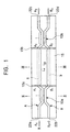
- Fig. 1 is a schematic plan view showing the construction
of an MZI optical switch according to a first embodiment of
the present invention;
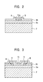
- Fig. 2 is a sectional view of Fig. 1 cut along line II-II;
- Fig. 3 is a sectional view of Fig. 1 cut along line III-III;
- Fig. 4 is a schematic plan view showing the construction
of an MZI optical switch according to a second embodiment of
the present invention;
- Fig. 5 is a graph showing the relationship between the
phase shift and the relative output light intensity in an MZI
optical switch in which δ/κ = 0.01;
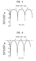
- Fig. 6 is a graph showing the relationship between the
phase shift and the relative output light intensity in an MZI
optical switch in which δ/κ = 0.1;
- Fig. 7 is a graph showing the relationship between the
phase shift and the relative output light intensity in an MZI
optical switch in which δ/κ = 0.2;
- Fig. 8 is a graph showing the relationship between the
phase shift and the relative output light intensity in an MZI
optical switch in which δ/κ = 0.5;
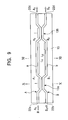
- Fig. 9 is a schematic plan view showing the construction
of an MZI temperature sensor according to a third embodiment
of the present invention;
- Fig. 10 is a sectional view of Fig. 9 cut along line X-X;
- Fig. 11 is a sectional view of Fig. 9 cut along line XI-XI;
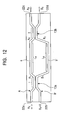
- Fig. 12 is a schematic plan view showing the
construction of an MZI temperature sensor according to a
fourth embodiment of the present invention;
- Fig. 13 is a graph showing the relationship between the
phase shift and the relative output light intensity in an MZI
temperature sensor in which δ/κ = 0.01;
- Fig. 14 is a graph showing the relationship between the
phase shift and the relative output light intensity in an MZI
temperature sensor in which δ/κ = 0.1;
- Fig. 15 is a graph showing the relationship between the
phase shift and the relative output light intensity in an MZI
temperature sensor in which δ/κ = 0.2;
- Fig. 16 is a graph showing the relationship between the
phase shift and the relative output light intensity in an MZI
temperature sensor in which δ/κ = 0.5;
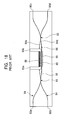
- Fig. 17 is a schematic plan view showing a known MZI
optical switch;
- Fig. 18 is a schematic plan view showing another known
MZI optical switch; and
- Fig. 19 is a schematic plan view showing a known MZI
temperature sensor.
-
DESCRIPTION OF THE PREFERRED EMBODIMENTS
-
Embodiments of the present invention will be described
in detail below with reference to the accompanying drawings.
(First Embodiment)
-
Fig. 1 is a schematic plan view showing the construction
of an MZI optical switch according to a first embodiment of
the present invention. In addition, Fig. 2 is a sectional
view of Fig. 1 cut along line II-II, and Fig. 3 is a
sectional view of Fig. 1 cut along line III-III.
-
As shown in Figs. 1 to 3, an MZI optical switch
according to the present embodiment includes a lower clad
layer 3a laminated on a substrate 2 composed of silicon or
the like; two optical waveguides A and B formed on the
surface of the lower clad layer 3a; an upper clad layer 3b
laminated so as to cover the two optical waveguides A and B
and the lower clad layer 3a; and a thin-film heater 15
composed of Cr or the like which is provided on the surface
of the upper clad layer 3b.
-
The lower and upper clad layers 3a and 3b are composed
of, for example, SiO2, and the refractive index of the
material of the lower and upper clad layers 3a and 3b is
lower than that of the material of the optical waveguides A
and B. In addition, the absolute value of the refractive
index temperature coefficient of the material of the lower
and upper clad layers 3a and 3b is also lower than that of
the material of the optical waveguides A and B.
-
The two optical waveguides A and B on the surface of the
lower clad layer 3a are in the vicinity of each other at two
locations so that two 3-dB directional couplers 13a and 13b
are provided, and include their respective optical waveguide
arms a and b which each is placed between the two 3-dB
directional couplers 13a and 13b. The refractive index
temperature coefficients of the two optical waveguides A and
B have opposite signs.
-
In the present embodiment, the optical waveguide A is
composed of a material which satisfies Expression (1) shown
below, that is, a material having a negative refractive index
temperature coefficient. For example, the optical waveguide
A is composed of one of TiO2, PbMoO4, and Ta2O5. In addition,
the optical waveguide B is composed of a material which
satisfies Expression (2) shown below, that is, a material
having a positive refractive index temperature coefficient.
For example, the optical waveguide B is composed of one of
LiNbO3, PLZT, and SiOxNy.
-
For the above-described reasons, preferably, the optical
waveguide A is composed of TiO2 and the optical waveguide B
is composed of PLZT.
(∂N/∂T)A < 0
(∂N/∂T)B > 0
where N is the refractive index of the optical waveguides A
and B and T is the temperature (°C).
-
In the above-mentioned materials of which the optical
waveguides A and B may be composed, the refractive index
temperature coefficient of TiO2 is -7×10⁻⁵°C-1, that of PbMoO4
is -4×10⁻⁵° C-1, that of Ta2O5 is -1×10⁻⁵° C-1, that of LiNbO3 is
4.0×10⁻⁵° C-1, that of PLZT is 10×10-5° C-1, and that of SiOxNy is
1×10⁻⁵° C-1.
-
The two optical waveguides A and B have the same
physical length, and the two optical waveguide arms a and b
also have the same physical length L.
-
The thin-film heater 15 heats at least one of the
optical waveguide arms a and b to cause a thermo-optic effect,
and thereby shifts the phase of transmitted light. In the
present embodiment, the thin-film heater 15 is provided above
the optical waveguide arms a and b with the upper clad layer
3b interposed therebetween, and therefore both of the optical
waveguide arms a and b are heated. The thin-film heater
(also referred to as an electrode) 15 is connected to metal
wires 15a and 15b.
-
In the MZI optical switch according to the present
embodiment, δ/κ ≤ 0.2 (δ is (βB-βA)/2 and κ is the coupling
coefficient, βA and βB being the transmission coefficients of
the optical waveguides A and B, respectively) is preferably
satisfied in view of increasing the extinction ratio. More
preferably, δ/κ ≤ 0.1 is satisfied, and an extinction ratio
of 30 dB or more can be obtained in such a case.
-
The relationship defined by δ/κ ≤ 0.2 can be satisfied
by reducing δ or increasing κ. δ can be reduced by changing
the cross sectional shapes of the optical waveguides A and B,
and κ can be increased by reducing the distance between the
optical waveguides A and B in the directional couplers 13a
and 13b.
-
Light with a wavelength of, for example, 1.3 µm or 1.55
µm, is caused to enter the optical waveguides of the above-described
MZI optical switch.
-
Next, the operation of the MZI optical switch according
to the present embodiment will be described below with
reference to Fig. 1.
-
In Fig. 1, reference symbols A0 to A3 and B0 to B3 denote
positions in the MZI optical switch. More specifically, A0
denotes a position of a first input port 22a provided on one
end of the optical waveguide A (position at which light
enters the optical waveguide A), A1 denotes a position on the
optical waveguide A immediately behind the 3-dB directional
coupler 13a which is near the first input port 22a, A2
denotes a position on the optical waveguide A immediately in
front of the 3-dB directional coupler 13b which is near the
other end of the optical waveguide A, and A3 denotes a
position of a first output port 22c provided on the other end
of the optical waveguide A.
-
In addition, B0 denotes a position of a second input
port 22b provided on one end of the optical waveguide B
(position at which light enters the optical waveguide B), B1
denotes a position on the optical waveguide B immediately
behind the 3-dB directional coupler 13a which is near the
second input port 22b, B2 denotes a position on the optical
waveguide B immediately in front of the 3-dB directional
coupler 13b which is near the other end of the optical
waveguide B, and B3 denotes a position of a second output
port 22d provided on the other end of the optical waveguide B.
-
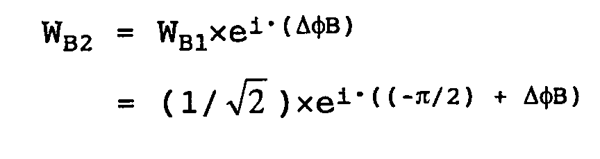
When no voltage is applied to the thin-film heater 15,
neither of the two optical waveguide arms a and b is heated.
In this state, when, for example, light R with a wavelength
of 1.55 µm is input to the first input port 22a, it is output
from the second output port 22d. The powers P
A0 to P
A3 and
P
B0 to P
B3 and the wave complex amplitudes W
A0 to W
A3 and W
B0
to W
B3 of the light R at positions A
0 to A
3 and B
0 to B
3,
respectively, are shown below. The normal transmission phase
shift is not included in the calculations. In this case, the
coupling ratios of the 3-dB directional couplers 13a and 13b
are both 0.5.
- Wave Complex Amplitude at Position A0:
WA0 = 1.0×ei· = 1
- Incident Light Power at Position A0:
PA0 = |WA0|2 = 1
- Wave Complex Amplitude at Position B0:
WB0 = 0,
which means no light enters.
- Incident Light Power at Position B0:
PB0 = |WB0|2 = 0
- Wave Complex Amplitude at Position A1:
WA1 = (1/2) WA0 = (1/2)
- Transmitted Light Power at Position A1:
PA1 = |WA1|2 = 1/2 (when 3-dB couplers are used)
- Wave Complex Amplitude at Position B1:
WB1 =(1/2)WA0×ei·(-π/2) = (1/2)×ei·(-π/2)
- Transmitted Light Power at Position B1:
PB1 = |WB1|2 = 1/2
- Wave Complex Amplitude at Position A2:
WA2 = WA1×ei·0 = (1/2)
- Transmitted Light Power at Position A2:
PA2 = |WA2|2 = 1/2
- Wave Complex Amplitude at Position B2:
WB2 = WB1×ei·0 = (1/2)×ei·(-π/2)
- Transmitted Light Power at Position B2:
PB2 = |WB2|2 = 1/2
- Wave Complex Amplitude at Position A3:
- Output Light Power at Position A3:
PA3 = |WA3|2 = 0,
which means that the power of output
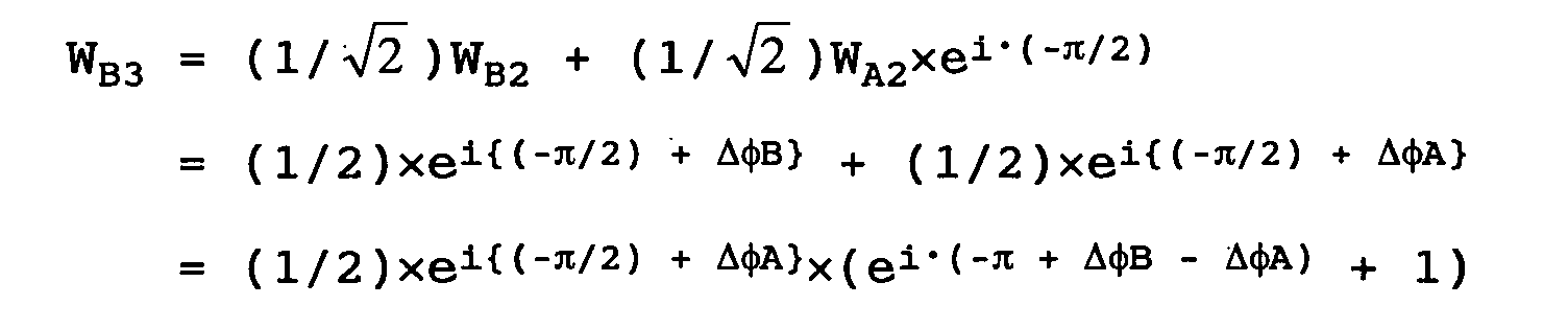
light is 0 and no light is emitted at position A3. - Wave Complex Amplitude at Position B3:
- Output Light Power at Position B3:
PB3 = |WB3|2 = 1,
which means that the power of output
light is 1.
-
-
When a voltage is applied to the thin-film heater 15,
both of the two optical waveguide arms a and b are heated by
the thin-film heater 15 and the temperature thereof increases.
At this time, since the refractive index temperature
coefficients of the two optical waveguide arms a and b have
opposite signs as described above, the difference between the
optical path lengths of the two optical waveguide arms a and
b is larger than that in the known MZI optical switch in
which the optical waveguides are composed of the same
material, and the phase of the transmitted light can be
shifted by π at a lower temperature. Accordingly, if, for
example, light R with a wavelength of 1.55 µm is input to the
first input port 22a, it is output from the first output port
22c.
-
The powers PA0 to PA3 and PB0 to PB3 and the wave complex
amplitudes WA0 to WA3 and WB0 to WB3 of the light R at
positions A0 to A3 and B0 to B3, respectively, are shown below.
The normal transmission phase shift is not included in the
calculations. In this case, the coupling ratios of the 3-dB
directional couplers 13a and 13b are both 0.5.
-
In this example, the case in which the optical waveguide
arms a and b are heated until Δ
A,B = Δ
B - Δ
A = π (Δ
A is the
phase difference of light which passes through the optical
waveguide arm a being heated and Δ
B is the phase difference
of light which passes through the optical waveguide arm b
being heated) is satisfied is considered. In addition, L
A =
L
B = L (L
A is the physical length of a portion of the optical
waveguide arm a which is covered by the thin-film heater 15,
and L
B is the physical length of a portion of the optical
waveguide arm b which is covered by the thin-film heater 15)
and N
A ≠ N
B (N
A is the refractive index of the optical
waveguide A and N
B is the refractive index of the optical
waveguide B) are satisfied.
- Wave Complex Amplitude at Position A0:
WA0 = 1.0×ei· = 1
- Incident Light Power at Position A0:
PA0 = |WA0|2 = 1
- Wave Complex Amplitude at Position B0:
WB0 = 0,
which means no light enters.
- Incident Light Power at Position B0:
PB0 = |WB0|2 = 0
- Wave Complex Amplitude at Position A1:
WA1 = (1/2)WA0 = (1/2)
- Transmitted Light Power at Position A1:
PA1 = |WA1|2 = 1/2
(when 3-dB couplers are used)
- Wave Complex Amplitude at Position B1:
WB1 =(1/2)WA0×ei·(-π/2) = (1/2)×ei·(-π/2)
- Transmitted Light Power at Position B1:
PB1 = |WB1|2 = ½
- Wave Complex Amplitude at Position A2:
- Transmitted Light Power at Position A2:
PA2 = |WA2|2 = ½
- Wave Complex Amplitude at Position B2:
- Transmitted Light Power at Position B2:
PB2 = |WB2|2 = 1/2
- Wave Complex Amplitude at Position A3:
- Since ΔB - ΔA = π, as described above,
- Output Light Power at Position A3:
PA3 = |WA3|2 = 1,
which means that the power of output
light is 1.
- Wave Complex Amplitude at Position B3:
- Since ΔB - ΔA = π, as described above,
- Output Light Power at Position B3:
PB3 = |WB3|2 = 0,
which means that the power of output
light is 0 and no light is emitted at position B3.
-
-
When A is the phase difference of light which passes
through the optical waveguide arm a and B is the phase
difference of light which passes through the optical
waveguide arm b, A and B are calculated as follows:
A = (2πL/λ)NA
where L is the physical length of a portion of the optical
waveguide arm a which is covered by the thin-film heater 15
and NA is the refractive index of the optical waveguide A.
B = (2πL/λ)NB
where L is the physical length of a portion of the optical
waveguide arm b which is covered by the thin-film heater 15
and NB is the refractive index of the optical waveguide B.
-
In addition, ΔA and ΔB are calculated as follows:
ΔA = (2πL/λ)(∂N/∂T)AΔT
where L is the physical length of a portion of the optical
waveguide arm a which is covered by the thin-film heater 15,
λ is the wavelength of incident light, and ΔT is the
temperature change.
ΔB = (2πL/λ)(∂N/∂T)BΔT
where L is the physical length of a portion of the optical
waveguide arm b which is covered by the thin-film heater 15,
λ is the wavelength of incident light, and ΔT is the
temperature change.
-
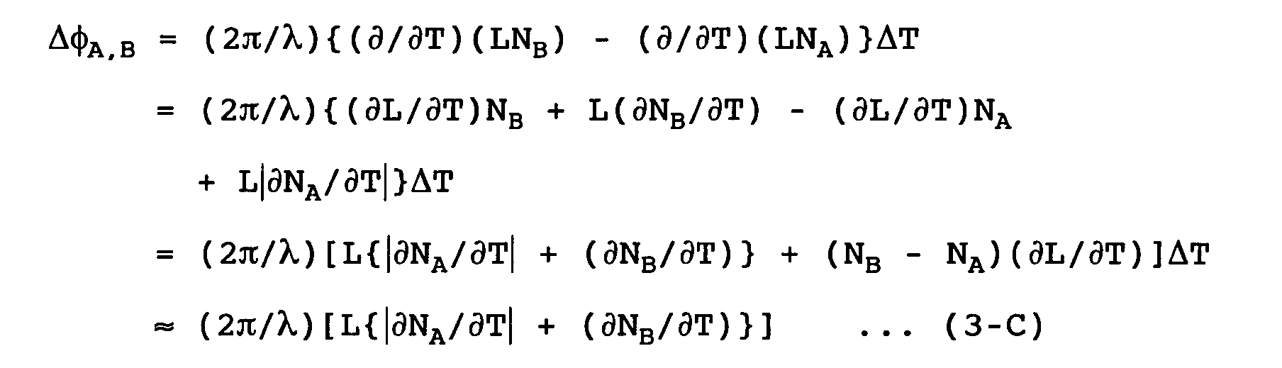
In addition, Δ
A,B is calculated as follows:
-
In the MZI optical switch according to the present
embodiment, the refractive index temperature coefficients of
the two optical waveguides A and B have opposite signs.
Therefore, the difference between the optical path lengths of
the two optical waveguide arms and the phase shift of the
transmitted light obtained when the optical waveguide arms
are heated are larger than those obtained in the known MZI
optical switch, which includes two optical waveguides
composed of the same material (in other words, two optical
waveguides whose refractive index temperature coefficients
are the same), if the same temperature change is caused.
-
In addition, in the MZI optical switch according to the
present embodiment, the phase of the transmitted light can be
shifted by the amount required to achieve switching at a
lower temperature compared to the known MZI optical switch in
which the two optical waveguides are composed of the same
material. Thus, the power consumption and the time required
to increase the temperature are reduced, and the switching
time is reduced accordingly.
-
In the known MZI optical switch in which the two optical
waveguides are composed of the same material, if the phase of
the transmitted light must be shifted by π to achieve
switching, the temperature change (ΔT)π required for shifting
the phase by π is calculated as follows:
(ΔT)π = λ/[2L(∂N/∂T)]
where L is the physical length of portions of the optical
waveguide arms which are covered by the thin-film heater 15,
and λ is the wavelength of incident light. In the known MZI
optical switch, the physical lengths of the optical waveguide
arms and the refractive indices satisfy LA = LB = L and NA =
NB.
-
In comparison, in the MZI optical switch according to
the present embodiment, if the phase of the transmitted light
must be shifted by n to achieve switching, the temperature
change (ΔT)π required for shifting the phase by π (ΔB - ΔA =
π) is calculated as follows:
(ΔT)π = λ/[2L{(∂N/∂T)B + |(∂N/∂T)A|}]
where L is the physical length of portions of the optical
waveguide arms a and b which are covered by the thin-film
heater 15, and λ is the wavelength of incident light.
-
The denominator of the right side of Equation (5) is
larger than that of the right side of Equation (4), and
therefore (ΔT)π of the MZI optical switch according to the
present embodiment is smaller than that of the known MZI
optical switch.
-
In the MZI optical switch according to the present
embodiment, both of the two optical waveguide arms a and b
are heated. Accordingly, compared to the case in which only
one of the optical waveguide arms a and b is heated, the
difference between the optical path lengths of the two
optical waveguide arms a and b increases, and the phase shift
of the transmitted light increases accordingly. Therefore,
compared to the case in which only one of the optical
waveguide arms a and b is heated, the phase of the
transmitted light can be shifted by the amount required to
achieve switching at a lower temperature. As a result, the
required temperature increase can be achieved in a shorter
time and the switching time is reduced.
-
In addition, since both of the two optical waveguide
arms a and b are heated in the MZI optical switch according
to the present embodiment, it is not necessary to provide a
thermal insulator between the two optical waveguide arms a
and b, and the structure and the manufacturing processes are
simple. In addition, the two optical waveguide arms a and b
can be arranged near each other, and therefore the bending
angle can be reduced. Accordingly, the optical loss and the
size of the MZI optical switch can be reduced.
-
In addition, in the MZI optical switch according to the
present embodiment, the two optical waveguides A and B are
simply composed of materials whose refractive index
temperature coefficients have opposite signs. Accordingly,
compared to the known MZI optical switch in which the grooves
filed with an organic material are formed along the optical
waveguide arms, the structure and the manufacturing processes
are simpler.
-
In the above-described embodiment, the thin-film heater
15 heats both of the optical waveguide arms a and b. However,
a thin-film heater which heats only one of the two optical
waveguide arms may also be provided in place of the thin-film
heater 15. For example, a thin-film heater which heats only
the optical waveguide arm a (hereinafter called a thin-film
heater according to a modification) may also be provided. In
such a case, the thin-film heater according to the
modification is provided above the optical waveguide arm a
with the upper clad layer 3b interposed therebetween, and no
thin-film heater is provided above the optical waveguide arm
b.
-
An MZI optical switch which is similar to the MZI
optical switch of the first embodiment except for having the
thin-film heater according to the modification will be
described below with reference to Fig. 1.
-
When no voltage is applied to the thin-film heater
according to the modification, the MZI optical switch
functions similarly to the MZI optical switch according to
the first embodiment. Accordingly, when, for example, light
R with a wavelength of 1.55 µm is input to the first input
port 22a, it is output from the second output port 22d.
-
When a voltage is applied to the thin-film heater
according to the modification, the optical waveguide arm a is
heated and the temperature thereof increases. At this time,
since the refractive index temperature coefficients of the
two optical waveguide arms a and b have opposite signs as
described above, the difference between the optical path
lengths of the two optical waveguide arms a and b is larger
than that in the known MZI optical switch in which the
optical waveguides are composed of the same material (not as
large as that in the case in which both of the optical
waveguide arms a and b are heated), and the phase of the
transmitted light can be shifted by π at a lower temperature.
Accordingly, if, for example, light R with a wavelength of
1.55 µm is input to the first input port 22a, it is output
from the first output port 22c.
-
The powers PA0 to PA3 and PB0 to PB3 and the wave complex
amplitudes WA0 to WA3 and WB0 to WB3 of the light R at
positions A0 to A3 and B0 to B3, respectively, are shown below.
The normal transmission phase shift is not included in the
calculations. In this case, the coupling ratios of the 3-dB
directional couplers 13a and 13b are both 0.5.
-
In this example, the case in which the optical waveguide
arm a is heated until Δ
A = -π (Δ
A is the phase difference
of light which passes through the optical waveguide arm a
being heated) is satisfied is considered. In addition, Δ
A <
0 is satisfied.
- Wave Complex Amplitude at Position A0:
WA0 = 1.0×ei· = 1
- Incident Light Power at Position A0:
PA0 = |WA0|2 = 1
- Wave Complex Amplitude at Position B0:
WB0 = 0,
which means no light enters.
- Incident Light Power at Position B0:
PB0 = |WB0|2 = 0
- Wave Complex Amplitude at Position A1:
WA1 = (1/2)WA0 = (1/2)
- Transmitted Light Power at Position A1:
PA1 = |WA1|2 = 1/2
(when 3-dB couplers are used)
- Wave Complex Amplitude at Position B1:
WB1 =(1/2)WA0×ei·(-π/2) = (1/2)×ei·(-π/2)
- Transmitted Light Power at Position B1:
PB1 = |WB1|2 = 1/2
- Wave Complex Amplitude at Position A2:
WA2 = WA1×ei·(ΔA) = (1/2)×ei·(ΔA)
- Transmitted Light Power at Position A2:
PA2 = |WA2|2 = 1/2
- Wave Complex Amplitude at Position B2:
WB2 = WB1×ei·(ΔB)
- Since ΔB = 0,
WB2 = WB1 = (1/2)×ei·(-π/2)
- Transmitted Light Power at Position B2:
PB2 = |WB2|2 = 1/2
- Wave Complex Amplitude at Position A3:
Since ΔA = -π, as described above,
WA3 = (1/2)×ei·π + (1/2)×ei·(-π) = -1
- Output Light Power at Position A3:
PA3 = |WA3|2 = 1,
which means that the power of output
light is 1.
- Wave Complex Amplitude at Position B3:
Since ΔA = -π, as described above,
WB3 = (1/2)×ei·(-π/2)×(1 - 1) = 0
- Output Light Power at Position B3:
PB3 = |WB3|2 = 0,
which means that the power of output
light is 0 and no light is emitted at position B3.
-
(Second Embodiment)
-
Fig. 4 is a schematic plan view showing the construction
of an MZI optical switch according to a second embodiment of
the present invention.
-
The MZI optical switch according to the second
embodiment differs from the MZI optical switch according to
the first embodiment shown in Figs. 1 to 3 in that the
lengths of two optical waveguides A and B' are different from
each other and are set such that the effective optical path
lengths of the optical waveguides A and B' for incident light
R with a predetermined wavelength are the same in the region
between directional couplers 13a and 13b. More specifically,
the physical length of an optical waveguide arm b' of the
optical waveguide B' is longer than that of an optical
waveguide arm a of the optical waveguide A such that the
effective optical path lengths of the optical waveguides A
and B' for the incident light R with the predetermined
wavelength are the same in the region between the directional
couplers 13a and 13b.
-
Also in the present embodiment, the optical waveguide A
is composed of a material similar to that used in the first
embodiment which has a negative refractive index temperature
coefficient, and the optical waveguide B' is composed of a
material similar to that used in the first embodiment which
has a positive refractive index temperature coefficient.
-
The reason why the MZI optical switch is constructed as
above will be described below.
-
In the MZI optical switch shown in Figs. 1 to 3, the
refractive index temperature coefficients of the two optical
waveguides A and B have opposite signs, and therefore there
may be a case in which the transmission coefficients of the
two optical waveguides A and B are different form each other
by a large amount. In such a case, if the effective optical
wavelengths of the optical waveguide arms a and b are
different from each other, the signal light (incident light)
cannot travel through the optical waveguide arms a and b in a
similar manner and switching offset occurs.
-
In the MZI optical switch shown in Fig. 1, if the power
of light input to the first input port 22a is 1, the energy
output ratio at the first output port 22c is calculated as
follows:
|WA3/WA0|2 = {cos2(ql) - sin2(ql)/q2)(δ2 + κ2cos(Δ'))}2
+ (sin2(ql)/q2)(2δcos(ql)
- (κ2/q)sin(ql)sin(Δ'))2
where WA0 is the incident amplitude of the light at the first
input port 22a, WA3 is the output amplitude of the light at
the first output port 22c, q is the effective coupling
coefficient, 1 is the coupling length of the 3-dB directional
couplers 13a and 13b, Δ' is the effective phase change, κ is
the coupling coefficient, and δ is one-half of the difference
between the transmission coefficients of the two optical
waveguides.
-
If the power of light input to the first input port 22a
is 1 and the sum of the energy output ratio at the first
output port 22c and that at the second output port 22d is 1,
the energy output ratio at the second output port 22d is
calculated as follows:
|WB3/WA0|2 = 1 - |WA3/WA0|2
where WB3 is the output amplitude at the second output port
22d.
-
In addition, δ is calculated as follows:
δ = (βB - βA)/2
where βA is the transmission coefficient of the optical
waveguide A and βB is the transmission coefficient of the
optical waveguide B.
-
If the transmission coefficients of the optical
waveguides A and B are different as above, the actual
coupling coefficient (effective coupling coefficient) q is
different from the coupling coefficient κ, and therefore the
actual phase change (effective phase change) Δ' obtained
when the optical waveguide arms a and b are heated is also
different from Δ.
-
The effective coupling coefficient q can be obtained as
follows:
q2 = κ2 + δ2
and the effective phase change Δ' can be obtained as
follows:
Δ' = Δ -2δ(L - 1)
where Δ is the phase difference obtained when the optical
waveguides A and B are composed of the same material, L is
the physical length of portions of the optical waveguide arms
which are covered by the thin-film heater 15, and 1 is the
coupling length of the 3-dB directional couplers 13a and 13b.
-
In the present embodiment, the physical length of the
optical waveguide arm b' of the optical waveguide B' is set
longer than that of the optical waveguide arm a of the
optical waveguide A such that the effective optical path
lengths of the optical waveguides A and B' for the incident
light R with the predetermined wavelength are the same in the
region between the directional couplers 13a and 13b. The
relationship between the physical lengths of the optical
waveguide arms a and b' is expressed as follows:
LB = LA + ΔL
where LA is the physical length of a portion of the optical
waveguide arm a which is covered by the thin-film heater 15,
LB is the physical length of a portion of the optical
waveguide arm b' which is covered by the thin-film heater 15,
and ΔL is the difference between LB and LA.
-
The switching offset can be prevented by adjusting ΔL as
follows:
ΔL = (1 - βA/βB)(LA - 1 + c/(2κ))
-
Since Equation (11) is satisfied, Equation (10) is
rewritten as follows:
Δ' = Δ - 2δ(LA - 1) + βB·ΔL
where 1 is the coupling length of the 3-dB directional
couplers 13a and 13b. Accordingly, the following equation is
obtained from Equations (10-2) and (12):
Δ' = Δ + c(δ/κ)
where c is the fitting parameter, and is determined as c ≈
1.5 when the offset is zero by numerical calculation (when
δ/κ = 0.5).
-
Since the transmission coefficient βA and βB are
different from each other unlike normal optical waveguides, a
phase difference occurs even when the physical lengths are
the same, and this leads to the offset. Accordingly, in
order to prevent the offset, the physical lengths are
adjusted as in Equation (12).
-
In the MZI optical switch according to the present
embodiment, the physical length of the optical waveguide arm
b' is set longer than that of the optical waveguide arm a in
accordance with the difference between the transmission
coefficients of the two optical waveguides A and B' such that
the effective optical path lengths of the optical waveguides
A and B' for the incident light R with the predetermined
wavelength between are the same in the region between the
directional couplers 13a and 13b. Accordingly, the switching
offset can be prevented.
(Examples)
-
MZI optical switches having a construction similar to
that of the MZI optical switch of the first embodiment shown
in Figs. 1 and 3 were manufactured, and δ/κ of the
manufactured MZI optical switches ranged from 0.01 to 0.5.
The parameters of 3-dB directional couplers used in the MZI
optical switches satisfied ql = π/4, where q is the effective
coupling coefficient, 1 is the coupling length of the
directional couplers, and π is the phase shift. The
extinction ratio of the manufactured MZI optical switches was
determined by inputting light with a wavelength of 1.55 µm to
the first input port 22a, measuring the power of light output
from the first output port 22c, and converting the phase
shift into an electrode voltage. The results are shown in
Figs. 5 to 8.
-
Fig. 5 is a graph showing the relationship between the
phase shift (rad) and the relative output light intensity
(dB) in an MZI optical switch in which δ/κ = 0.01.
-
Fig. 6 is a graph showing the relationship between the
phase shift (rad) and the relative output light intensity
(dB) in an MZI optical switch in which δ/κ = 0.1.
-
Fig. 7 is a graph showing the relationship between the
phase shift (rad) and the relative output light intensity
(dB) in an MZI optical switch in which δ/κ = 0.2.
-
Fig. 8 is a graph showing the relationship between the
phase shift (rad) and the relative output light intensity
(dB) in an MZI optical switch in which δ/κ = 0.5.
-
As is clear from Figs. 5 to 8, the extinction ratio of
the MZI optical switch in which δ/κ = 0.5 was only 14 dB,
whereas the extinction ratios of the MZI optical switches in
which δ/κ ≤ 0.2 were 28 dB or more. In particular, the
extinction ratios of the MZI optical switches in which δ/κ ≤
0.1 were 40 dB or more. Accordingly, δ/κ ≤ 0.1 is preferably
satisfied for obtaining an extinction ratio of 30 dB or more,
which is preferable in terms of practicability.
-
As described above, according to the MZI optical switch
of the present invention, the refractive index temperature
coefficients of the two optical waveguides have opposite
signs. Thus, the present invention provides an MZI optical
switch with a simple structure, low power consumption, and
short switching time.
(Third Embodiment)
-
Fig. 9 is a schematic plan view showing the construction
of an MZI temperature sensor according to a third embodiment
of the present invention. In addition, Fig. 10 is a
sectional view of Fig. 9 cut along line X-X, and Fig. 11 is a
sectional view of Fig. 9 cut along line XI-XI.
-
As shown in Figs. 9 to 11, an MZI temperature sensor
according to the present embodiment includes a lower clad
layer 3a laminated on a substrate 2 composed of silicon or
the like; two optical waveguides A and B formed on the
surface of the lower clad layer 3a; and an upper clad layer
3b laminated so as to cover the two optical waveguides A and
B and the lower clad layer 3a.
-
The lower and upper clad layers 3a and 3b are composed
of, for example, SiO2, and the refractive index of the
material of the lower and upper clad layers 3a and 3b is
lower than that of the material of the optical waveguides A
and B. In addition, the absolute value of the refractive
index temperature coefficient of the material of the lower
and upper clad layers 3a and 3b is also lower than that of
the material of the optical waveguides A and B.
-
The two optical waveguides A and B on the surface of the
lower clad layer 3a are in the vicinity of each other at two
locations so that two 3-dB directional couplers 13a and 13b
are provided, and include their respective optical waveguide
arms a and b which each is placed between the two 3-dB
directional couplers 13a and 13b.
-
The refractive index temperature coefficients of the two
optical waveguides A and B have opposite signs. In the
present embodiment, the optical waveguide A is composed of a
material which satisfies Expression (21) shown below, that is,
a material having a negative refractive index temperature
coefficient. For example, the optical waveguide A is
composed of one of TiO2, PbMoO4, and Ta2O5.
-
In addition, the optical waveguide B is composed of a
material which satisfies Expression (22) shown below, that is,
a material having a positive refractive index temperature
coefficient. For example, the optical waveguide B is
composed of one of LiNbO3, PLZT, and SiOxNy. The refractive
index of SiOxNy is about 1.48 to 1.9 (the refractive index
increases as y increases (as the amount of N increases)).
-
For the above-described reasons, preferably, the optical
waveguide A is composed of TiO2 and the optical waveguide B
is composed of PLZT.
(∂N/∂T)A < 0
(∂N/∂T)B > 0
where N is the refractive index of the optical waveguides A
and B and T is the temperature (°C).
-
In the above-mentioned materials of which the optical
waveguides A and B may be composed, the refractive index
temperature coefficient of TiO2 is -7×10⁻⁵°C-1, that of PbMoO4
is -4×10⁻⁵° C-1, that of Ta2O5 is -1×10⁻⁵° C-1, that of LiNbO3 is
4.0×10⁻⁵° C-1, that of PLZT is 10×10-5° C-1, and that of SiOxNy is
1×10⁻⁵° C-1.
-
The two optical waveguides A and B have the same
physical length, and the two optical waveguide arms a and b
also have the same physical length.
-
In the MZI temperature sensor according to the present
embodiment, δ/κ ≤ 0.2 (δ is (βB-βA)/2 and κ is the coupling
coefficient, βA and βB being the transmission coefficients of
the optical waveguides A and B, respectively) is preferably
satisfied in view of increasing the extinction ratio and
obtaining the output more accurately. In such a case, the
temperature resolution can be increased when analog
processing of the temperature change is performed. More
preferably, δ/κ ≤ 0.1 is satisfied, and an extinction ratio
of 30 dB or more can be obtained in such a case. The
relationship defined by δ/κ ≤ 0.2 can be satisfied by
reducing δ or increasing κ. δ can be reduced by changing the
cross sectional shapes of the optical waveguides A and B, and
κ can be increased by reducing the distance between the
optical waveguides A and B in the directional couplers 13a
and 13b.
-
Light with a wavelength of, for example, 1.3 µm or 1.55
µm, is caused to enter the optical waveguides of the above-described
MZI temperature sensor.
-
Next, the operation of the MZI temperature sensor
according to the present embodiment will be described below
with reference to Fig. 9. In Fig. 9, reference symbols A0 to
A3 and B0 to B3 denote positions in the MZI temperature
sensor.
-
More specifically, A0 denotes a position of a first
input port 22a provided on one end of the optical waveguide A
(position at which light enters the optical waveguide A), A1
denotes a position on the optical waveguide A immediately
behind the 3-dB directional coupler 13a which is near the
first input port 22a, A2 denotes a position on the optical
waveguide A immediately in front of the 3-dB directional
coupler 13b which is near the other end of the optical
waveguide A, and A3 denotes a position of a first output port
22c provided on the other end of the optical waveguide A.
-
In addition, B0 denotes a position of a second input
port 22b provided on one end of the optical waveguide B
(position at which light enters the optical waveguide B), B1
denotes a position on the optical waveguide B immediately
behind the 3-dB directional coupler 13a which is near the
second input port 22b, B2 denotes a position on the optical
waveguide B immediately in front of the 3-dB directional
coupler 13b which is near the other end of the optical
waveguide B, and B3 denotes a position of a second output
port 22d provided on the other end of the optical waveguide B.
-
When, for example, light R with a wavelength of 1.55 µm
is input to the first input port 22a while there is no
temperature change (or before a temperature change occurs),
it is output from the second output port 22d. The incident
light powers, the output light powers, and the phase shifts
(or the wave complex amplitudes) at positions A
0 to A
3 and B
0
to B
3 are shown below. In this case, the coupling ratios of
the 3-dB directional couplers 13a and 13b are both 0.5.
- Incident Light Power at Position A0: 1
- Wave Complex Amplitude at Position A1: (1/ 2 )×ei·0
- Wave Complex Amplitude at Position A2: (1/ 2 )×ei·0
- Output Light Power at Position A3: 0 (this is obtained
from (1/ 2 )×(1/ 2 )×ei·0 + (1/ 2 )×(1/ 2 )×ei·(-π/2) = 0)
- Incident Light Power at Position B0: 0
- Wave Complex Amplitude at Position B1: (1/ 2 )×ei·(-π/2)
- Wave Complex Amplitude at Position B2: (1/ 2 )×ei·(-π/2)
- Output Light Power at Position B3: 1 (this is obtained
from |WB3|2 = 1, which is derived from (1/ 2 )×(1/ 2 )×ei·(-π/2) +
(1/ 2 )×(1/ 2 )×ei·(-π/2))
-
-
When there is a temperature change, the temperature
increases at both of the two optical waveguide arms a and b.
At this time, since the refractive index temperature
coefficients of the two optical waveguide arms a and b have
opposite signs as described above, the difference between the
optical path lengths of the two optical waveguide arms a and
b is larger than that in the known MZI temperature sensor in
which the optical waveguides are composed of the same
material, and a phase shift of π, which is required for the
temperature detection, can be obtained even when the
temperature change is small (even when the temperature is
low). Accordingly, if, for example, light R with a
wavelength of 1.55 µm is input to the first input port 22a,
it is output from the first output port 22c. The power of
the output light varies periodically with respect to the
temperature, and since the temperature and the output light
power are in one-to-one correspondence in each period, the
temperature can be determined on the basis of the light
intensity.
-
The incident light powers, the output light powers, and
the phase shifts (or the wave complex amplitudes) at
positions A0 to A3 and B0 to B3 are shown below.
-
In this example, the case in which the temperature of
the optical waveguide arms a and b is increased until Δ
A,B =
Δ
B - Δ
A = π (Δ
A is the phase difference of light which
passes through the optical waveguide arm a being heated and
Δ
B is the phase difference of light which passes through the
optical waveguide arm b being heated) is satisfied is
considered. In addition, L
A = L
B = L (L
A is the physical
length of the optical waveguide arm a and L
B is the physical
length of the optical waveguide arm b), NA ≠ N
B (N
A is the
refractive index of the optical waveguide A and N
B is the
refractive index of the optical waveguide B), Δ
A < 0, and
Δ
B > 0 are satisfied.
- Incident Light Power at Position A0: 1
- Wave Complex Amplitude at Position A1: (1/ 2 )×ei·0
- Wave Complex Amplitude at Position A2: (1/ 2 )×ei·ΔA
- Output Light Power at Position A3: 1 (this is obtained
from |WA3|2 = 1, which is derived by substituting ΔA,B = ΔB -
ΔA = π into (1/ 2 )×(1/ 2 )×ei·ΔA + (1/ 2 )×(1/ 2 )×ei·(-π + ΔB),
where ΔA means ΔA and ΔB means ΔB)
- Incident Light Power at Position B0: 0
- Wave Complex Amplitude at Position B1: (1/ 2 )xei·(-π/2)
- Wave Complex Amplitude at Position B2:
(1/2)×ei·((-π/2) + ΔB)
- Output Light Power at Position B3: 0 (this is obtained
from |WB3|2 = 0, which is derived by substituting ΔA,B = ΔB -
ΔA = π into (1/ 2 )×(1/ 2 )×ei·(ΔA - π/2) +
(1/ 2 )×(1/ 2 )×ei·((-π/2) + ΔB) , where ΔA means ΔA and ΔB
means ΔB)
-
-
When
A is the phase difference of light which passes
through the optical waveguide arm a and
B is the phase
difference of light which passes through the optical
waveguide arm b,
A and
B are calculated as follows:
- A and B are calculated as follows:
A = (2πL/λ)NA
where L is the physical length of the optical waveguide arm a
and NA is the refractive index of the optical waveguide A.
B = (2πL/λ)NB
where L is the physical length the optical waveguide arm b
and NB is the refractive index of the optical waveguide B.-
-
In addition, ΔA and ΔB are calculated as follows:
ΔA = (2πL/λ)(∂N/∂T)AΔT
where L is the physical length of the optical waveguide arm a,
λ is the wavelength of incident light, and ΔT is the
temperature change.
ΔB = (2πL/λ)(∂N/∂T)BΔT
where L is the physical length of the optical waveguide arm b,
λ is the wavelength of incident light, and ΔT is the
temperature change.
-
In addition, Δ
A,B is calculated as follows:
-
In the MZI temperature sensor according to the present
embodiment, the refractive index temperature coefficients of
the two optical waveguides A and B have opposite signs.
Therefore, the difference between the effective optical path
lengths of the two optical waveguide arms and the phase shift
of the transmitted light obtained when a temperature change
occurs are larger than those obtained in the known MZI
temperature sensor, which includes two optical waveguides
composed of the same material (in other words, two optical
waveguides whose refractive index temperature coefficients
are the same), if the difference between the physical lengths
of the two optical wavelengths is the same.
-
In addition, in the MZI temperature sensor according to
the present embodiment, the phase of the transmitted light
can be shifted by the amount required to detect the
temperature change even when the temperature change is small.
Accordingly, the temperature sensitivity is higher than that
of the known MZI temperature sensor in which the two optical
waveguides are composed of the same material.
-
In the known MZI temperature sensor in which the two
optical waveguides are composed of the same material, if the
phase of the transmitted light must be shifted by π to detect
the temperature change, the temperature change (ΔT)π required
for shifting the phase by π is calculated as follows:
(ΔT)π = λ/[2{ΔL(∂N/∂T) + N(∂ΔL/∂T)}]
where L is the physical length of the optical waveguide arms
and λ is the wavelength of incident light. In the known MZI
temperature sensor, the physical lengths of the optical
waveguide arms and the refractive indices satisfy the
following expressions:
LA < LB , LB = LA + ΔL, NA = NB = N,
and
(∂N/∂T)A = (∂N/∂T)B = (∂N/∂T)
-
When, for example, the two optical waveguides included
in the known MZI temperature sensor are composed of LiNbO3
(the refractive index N = 2.2 and (∂N/∂T) = 4×10⁻⁵° C-1) and
when ΔL = 0.01 cm, LA = 5 cm, λ = 0.633 µm, and (∂ΔL/∂T) =
1.6 × 10⁻⁵° C-1, (ΔT)π = 42 °C is obtained from Equation (24).
-
In comparison, in the MZI temperature sensor according
to the present embodiment, if the phase of the transmitted
light must be shifted by π to detect the temperature change,
the temperature change (ΔT)π required for shifting the phase
by π is calculated as follows:
(ΔT)π = λ/[2L{(∂N/∂T)B + |(∂N/∂T)A|}]
where L is the physical length of the optical waveguide arms
and λ is the wavelength of incident light. Equation (25)
corresponds to the case in which LA = LB is satisfied, as
shown in Fig. 9. The case in which LA < LB is satisfied, as
shown in Fig. 12, will be describe below in the fourth
embodiment.
-
The denominator of the right side of Equation (25) is
larger than that of the right side of Equation (24), and
therefore (ΔT)π of the MZI temperature sensor according to
the present embodiment is smaller than that of the known MZI
temperature sensor.
-
When, for example, the optical waveguides A and B
included in the MZI temperature sensor according to the
present embodiment is composed of TiO2 (the refractive index
is NA = 2.2 and (∂N/∂T)A = -7×10⁻⁵°C-1) and SiOxNy (the
refractive index is NB = 1.48 to 1.9 and (∂N/∂T)B = 1×10⁻⁵° C-1),
respectively, and when L = 5 cm and λ = 0.633 µm, (ΔT)π <
0.1°C is obtained from Equation (25).
-
Accordingly, the MZI temperature sensor according to the
present invention can detect the temperature change at a
lower temperature compared to the known MZI temperature
sensor.
-
In addition, in the MZI temperature sensor according to
the present embodiment, the two optical waveguides A and B
are simply composed of materials whose refractive index
temperature coefficients have opposite signs. Therefore, the
structure and the manufacturing processes are simple.
Accordingly, the MZI temperature sensor according to the
present embodiment is suitable for mass production.
-
In addition, in the MZI temperature sensor according to
the present embodiment, the two optical waveguide arms may
have the same physical length. Therefore, the two optical
waveguide arms may be arranged nearer and the bending angle
can be reduced. Accordingly, the optical loss can be reduced
and the offset can be prevented. In addition, the size of
the MZI temperature sensor can be reduced.
(Fourth Embodiment)
-
Fig. 12 is a schematic plan view showing the
construction of an MZI temperature sensor according to a
fourth embodiment of the present invention.
-
The MZI temperature sensor according to the fourth
embodiment differs from the MZI temperature sensor according
to the third embodiment shown in Figs. 9 to 11 in that the
physical lengths of two optical waveguides A and B' are
different from each other. More specifically, the physical
length of an optical waveguide arm b' of the optical
waveguide B' is longer than that of an optical waveguide arm
a of the optical waveguide A.
-
Also in the present embodiment, the optical waveguide A
is composed of a material similar to that used in the third
embodiment which has a negative refractive index temperature
coefficient, and the optical waveguide B' is composed of a
material similar to that used in the third embodiment which
has a positive refractive index temperature coefficient.
-
The relationship between the physical length of the
optical waveguide arm a and that of the optical waveguide arm
b' is expressed as follows:
LB = LA + ΔL
where LA is the physical length of the optical waveguide arm
a, LB is the physical length of the optical waveguide arm b',
and ΔL is the difference between LB and LA.
-
In the present embodiment, Δ
A,B is calculated as
follows:
-
In the MZI temperature sensor according to the present
embodiment, if the phase of the transmitted light must be
shifted by π to detect the temperature change, the
temperature change (ΔT)π required for shifting the phase by π
is calculated as follows:
(ΔT)π = λ/[2{LB(∂N/∂T)B + LA|(∂N/∂T)A|
+ [NB(∂LB/∂T) - NA(∂LA/∂T)]}]
where LA is the physical length of the optical waveguide arm
a, LB is the physical length of the optical waveguide arm b',
and λ is the wavelength of incident light.
-
The denominator of the right side of Equation (27) is
larger than that of the right side of Equation (24), and
therefore (ΔT)π of the MZI temperature sensor according to
the present embodiment is smaller than that of the known MZI
temperature sensor.
-
When, for example, the optical waveguide A and B
included in the MZI temperature sensor according to the
present embodiment is composed of TiO2 (the refractive index
is NA = 2.2 and (∂N/∂T)A = -7×10⁻⁵°C-1) and SiOxNy (the
refractive index is NB = 1.48 to 1.9 and (∂N/∂T)B = 1×10⁻⁵° C-1),
respectively, and when LA = 5 cm, LB = 5.01 cm, ΔL = 0.01
cm, and λ = 0.633 µm, (ΔT)π < 0.1°C is obtained from Equation
(27)
(Examples)
-
MZI temperature sensors having a construction similar to
that of the MZI temperature sensor of the third embodiment
shown in Figs. 9 and 11 were manufactured, and δ/κ of the
manufactured MZI temperature sensors ranged from 0.01 to 0.5.
The parameters of 3-dB directional couplers used in the MZI
temperature sensors satisfied ql = π/4, where q is the
effective coupling coefficient, l is the coupling length of
the directional couplers, and π is the phase shift. The
extinction ratio of the manufactured MZI temperature sensors
was determined by inputting light with a wavelength of 1.55
µm to the first input port 22a, measuring the power of light
output from the first output port 22c, and converting the
phase shift into an electrode voltage.
-
The results are shown in Figs. 13 to 16.
-
Fig. 13 is a graph showing the relationship between the
phase shift (rad) and the relative output light intensity
(dB) in an MZI temperature sensor in which δ/κ = 0.01.
-
Fig. 14 is a graph showing the relationship between the
phase shift (rad) and the relative output light intensity
(dB) in an MZI temperature sensor in which δ/κ = 0.1.
-
Fig. 15 is a graph showing the relationship between the
phase shift (rad) and the relative output light intensity
(dB) in an MZI temperature sensor in which δ/κ = 0.2.
-
Fig. 16 is a graph showing the relationship between the
phase shift (rad) and the relative output light intensity
(dB) in an MZI temperature sensor in which δ/κ = 0.5.
-
As is clear from Figs. 13 to 16, the extinction ratio of
the MZI temperature sensor in which δ/κ = 0.5 was only 14 dB,
whereas the extinction ratios of the MZI temperature sensors
in which δ/κ ≤ 0.2 were 28 dB or more. In particular, the
extinction ratios of the MZI temperature sensors in which δ/κ
≤ 0.1 were 40 dB or more. Accordingly, δ/κ ≤ 0.1 is
preferably satisfied for obtaining an extinction ratio of 30
dB or more, which is preferable in terms of practicability.
-
As described above, according to the MZI temperature
sensor of the present invention, the refractive index
temperature coefficients of the two optical waveguides have
opposite signs. Thus, the present invention provides a high-sensitivity
MZI temperature sensor.