EP1469257A2 - Door assembly for microwave oven - Google Patents
Door assembly for microwave oven Download PDFInfo
- Publication number
- EP1469257A2 EP1469257A2 EP04002585A EP04002585A EP1469257A2 EP 1469257 A2 EP1469257 A2 EP 1469257A2 EP 04002585 A EP04002585 A EP 04002585A EP 04002585 A EP04002585 A EP 04002585A EP 1469257 A2 EP1469257 A2 EP 1469257A2
- Authority
- EP
- European Patent Office
- Prior art keywords
- latch
- door
- door assembly
- levers
- switches
- Prior art date
- Legal status (The legal status is an assumption and is not a legal conclusion. Google has not performed a legal analysis and makes no representation as to the accuracy of the status listed.)
- Granted
Links
Images






Classifications
-
- H—ELECTRICITY
- H05—ELECTRIC TECHNIQUES NOT OTHERWISE PROVIDED FOR
- H05B—ELECTRIC HEATING; ELECTRIC LIGHT SOURCES NOT OTHERWISE PROVIDED FOR; CIRCUIT ARRANGEMENTS FOR ELECTRIC LIGHT SOURCES, IN GENERAL
- H05B6/00—Heating by electric, magnetic or electromagnetic fields
- H05B6/64—Heating using microwaves
- H05B6/6414—Aspects relating to the door of the microwave heating apparatus
- H05B6/6417—Door interlocks of the microwave heating apparatus and related circuits
-
- F—MECHANICAL ENGINEERING; LIGHTING; HEATING; WEAPONS; BLASTING
- F24—HEATING; RANGES; VENTILATING
- F24C—DOMESTIC STOVES OR RANGES ; DETAILS OF DOMESTIC STOVES OR RANGES, OF GENERAL APPLICATION
- F24C15/00—Details
- F24C15/02—Doors specially adapted for stoves or ranges
- F24C15/022—Latches
-
- Y—GENERAL TAGGING OF NEW TECHNOLOGICAL DEVELOPMENTS; GENERAL TAGGING OF CROSS-SECTIONAL TECHNOLOGIES SPANNING OVER SEVERAL SECTIONS OF THE IPC; TECHNICAL SUBJECTS COVERED BY FORMER USPC CROSS-REFERENCE ART COLLECTIONS [XRACs] AND DIGESTS
- Y10—TECHNICAL SUBJECTS COVERED BY FORMER USPC
- Y10S—TECHNICAL SUBJECTS COVERED BY FORMER USPC CROSS-REFERENCE ART COLLECTIONS [XRACs] AND DIGESTS
- Y10S292/00—Closure fasteners
- Y10S292/69—Washing machine or stove closure latch
-
- Y—GENERAL TAGGING OF NEW TECHNOLOGICAL DEVELOPMENTS; GENERAL TAGGING OF CROSS-SECTIONAL TECHNOLOGIES SPANNING OVER SEVERAL SECTIONS OF THE IPC; TECHNICAL SUBJECTS COVERED BY FORMER USPC CROSS-REFERENCE ART COLLECTIONS [XRACs] AND DIGESTS
- Y10—TECHNICAL SUBJECTS COVERED BY FORMER USPC
- Y10T—TECHNICAL SUBJECTS COVERED BY FORMER US CLASSIFICATION
- Y10T292/00—Closure fasteners
- Y10T292/08—Bolts
- Y10T292/0801—Multiple
- Y10T292/0848—Swinging
- Y10T292/0849—Operating means
- Y10T292/0857—Lever
-
- Y—GENERAL TAGGING OF NEW TECHNOLOGICAL DEVELOPMENTS; GENERAL TAGGING OF CROSS-SECTIONAL TECHNOLOGIES SPANNING OVER SEVERAL SECTIONS OF THE IPC; TECHNICAL SUBJECTS COVERED BY FORMER USPC CROSS-REFERENCE ART COLLECTIONS [XRACs] AND DIGESTS
- Y10—TECHNICAL SUBJECTS COVERED BY FORMER USPC
- Y10T—TECHNICAL SUBJECTS COVERED BY FORMER US CLASSIFICATION
- Y10T292/00—Closure fasteners
- Y10T292/08—Bolts
- Y10T292/0801—Multiple
- Y10T292/0848—Swinging
- Y10T292/0849—Operating means
- Y10T292/0859—Push or pull rod
Definitions
- the present invention relates to microwave ovens, and more particularly, to a door assembly for a microwave oven, having an improved structure.
- the microwave oven cooks food with intermolecular friction heat generated when molecular array of food is disturbed by a high frequency wave (approx. 2,450MHz).
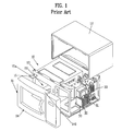
- FIG. 1 illustrates a perspective view of a related art microwave oven.
- the related art microwave oven is provided with a body 10, an inner case 20, and an outfit chamber.
- the body 10 is provided with a front case 11, an outer case 12, and a frame 13.
- the inner case 20 is provided inside of the body 10 for holding the food therein.
- the front case 11 is in a front part of the microwave oven, with a door 14 at one side thereof for opening/closing a front part of the inner case 20.
- the outer case 12 covers top and side surfaces of the microwave oven, with front edges thereof fastened to the front case 11.
- the frame 13 covers a bottom and rear surfaces of the body 10, to protect the inner case 20 and the outfit chamber 30 from an external environment together with the outer case 12 and the front case 11.
- the outfit chamber is formed on a side of the inner case 20 for providing various electric components thereto, including a magnetron 31, a high voltage transformer 32, and a fan 33.
- the magnetron 31 provides a microwave to an inside of the inner case 20 for heating food.
- the high voltage transformer 32 provides a high voltage power to the magnetron 31.
- the fan 33 blows air into an inside of the body 10, for cooling various electric components.
- brackets 15 fixed to a front surface of the frame 13, and the door 14 rotatably fixed to the brackets 15 opens/closes a front surface of the inner case 20.
- a latch on a door panel 141 pushes a lever on a latch board in the body 10, to operate a switch.
- FIG. 2 illustrates a side view of a latch board in a related art microwave oven
- FIG. 3 illustrates a diagram showing operation of an actuator 'A' of a switch 'S' when the latch 142 of the door is inserted into a latch board 101.
- the frame 13 is on a front surface of the inner case 20, and the latch board 101 is on the frame 13.
- the latch board 101 has three levers L1, L2, and L3, and 3 ⁇ 5 switches 'S' fitted therein.
- the switches 'S' include a first safety switch S1, a second safety switch S2, and a monitor switch S3.
- the first safety switch 'S1' is in a lower part of the latch board 101
- the monitor switch 'S3' is in a central part
- the second safety switch 'S2' in an upper part.
- Each of the switches 'S' is fastened to the latch board 101 with two fastening pins 'P' and a hook 'H'.
- latch inlets 103 in a front part of the latch board 101 for inserting the latch 142a.
- An upper latch inlet 103 has a sloped surface 104 for guiding an upper latch 142a to upward.
- the upper latch 142 is engaged with one end of the first lever L1 as the upper latch 142a moves up along the sloped surface 104 and drops at an end of the sloped surface 104. In this instance, the upper latch 142a pushes the first lever L1.
- a lower latch 142b is inserted into a lower latch inlet 103.
- the lower latch 142b pushes both one end of the second lever L2 and one end of the third lever L3 below the second lever L2.
- the first lever L1 operates the second safety switch S2
- the second lever L2 operates the monitor switch S3
- the third lever L3 operates the first safety switch S1.
- FIG. 4 illustrates fitting of the pin to the related art door
- FIG. 5 illustrates fastening of the pin
- the horizontal member 50 is extended form an edge of the door 14.
- the horizontal member 50 has a pin 55 fastened thereto for serving as a rotation shaft of the door 14.
- the horizontal member 50 has a hole 51 formed therein, for inserting the pin 55 therein.
- the pin 55 has a flange at a middle part thereof.
- the flange 50 is held by a lower surface of the horizontal member 50, when an extension 57 from a rear end of the pin 55 is projected by a length beyond the horizontal member 50.
- the extension 57 is flattened by caulking.
- the pin 55 is fastened to one side of the horizontal member 50.
- the brackets 15 are on one side of the frame 13.
- the bracket 15 has a hole 15a in one end part thereof, to which the pin 55 is inserted.
- the door 14 is rotatably mounted on the frame 13.
- the pin 55 serves as a rotation shaft of the door.
- the related art door latch board has the following problems.
- the present invention is directed to a door assembly for a microwave oven that substantially obviates one or more of the problems due to limitations and disadvantages of the related art.
- An object of the present invention is to provide a door assembly for a microwave oven that has a simple and convenient assembly structure.
- the door assembly for a microwave oven includes a door panel at one side of the door, having a push bar and a latch both projected from one side toward a body, and a latch board including levers each fitted rotatable at contact with the latch or the push bar, and switches each operable at contact with the lever.
- At least one of the levers has at least three arms.
- the levers include a first lever for being brought into contact with the push bar, and a second lever for being brought into contact with the latch.
- the second lever includes a third arm for being brought into contact with the latch, and a second arm, and a first arm for operating the switches respectively when the third arm is pushed and rotated by the latch.
- the first lever includes a second arm for being brought into contact with the push bar, and a first arm for operating the switch when the second arm is pushed and rotated by the push bar.
- the door panel is preferably formed as one unit with the door.
- the latch board includes a push bar hole and a latch hole for inserting the push bar and the latch, respectively.
- the latch has a sloped surface at an end part for inserting the latch into the latch hole as the sloped surface slides the latch hole.
- the latch hole includes a projection on an inside edge for hooking the latch. The lever is held by an upper side of the projection.
- the door assembly further includes a spring having one end hooked at a hook at one side of the latch, and the other end held in an upper part of the door panel.
- the spring provides a restoring force for rotating the latch, which pushes the arm of the lever.
- the switches are fitted on a front surface and a rear surface of the latch board in parallel.
- the latch board has a fastening pin and boss, and the switch has holes for inserting the fastening pin and the boss, for fastening the switch to the latch board with screw fastened to the boss.
- the levers rotate to original positions when the levers are disengaged from the latch or the push bar.
- the latch board has stoppers for holding the levers at preset positions, respectively.
- the levers are fitted to rotation shafts projected from the door panel respectively, and the levers fitted to the rotation shafts are held by hooks, respectively.
- the lever has a sloped surface at a part the lever is brought into contact with the hook in fitting the lever to the rotation shaft.
- a door assembly for a microwave oven including a door panel at one side of the door, having a push bar and a latch both projected from one side toward a body, and a latch board including levers each fitted rotatable at contact with the latch or the push bar, a board wall for dividing a front surface and a rear surface, and switches fitted on the front and rear surfaces of the board wall in parallel.
- the board wall has pass through holes formed therein, and the levers have extensions rotatable along the pass through holes, respectively.
- the levers operate switches on the front surface respectively, and the extensions operate the switches on the rear surfaces respectively.
- the switches include a first safety switch, a second safety switch, and a monitor switch, and switches are fitted parallel to, and on opposite side of the switches.
- a door assembly for a microwave oven including horizontal members each extended from an upper part, or a lower part of an edge of the door, pins each formed as one unit with one of the horizontal members, and brackets on a frame of the microwave oven, each having a hole for rotatably inserting the pin.
- the pin is a projection from the horizontal member formed by pressing.
- the horizontal members are formed as one unit with the door.
- a door assembly for a microwave oven including a latch assembly including a door panel at one side of a door for the microwave oven, a push bar projected from the door panel toward a body, a latch rotatably fitted to the door panel spaced a distance away from the push bar, a spring having one end held at an upper part of the door panel, and the other end connected to the latch, and a fastening pin fastened through the door panel and the latch to serve as a rotation shaft of the latch, and a latch board including levers rotatable at contact with the latch and the push bar respectively, and switches operable at contact with the levers respectively.
- the door assembly further includes a handle linked with the latch, and fitted rotatable around the fastening pin.
- the fastening pin has a head clamped between the door and the door panel.
- the spring provides a restoring force for rotating the latch in one direction.
- the door assembly further includes a projection on one side part of the door panel for holding the latch such that the latch rotates no more than a desired angle.
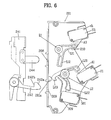
- FIG 6 illustrates a diagram showing latches and a latch board in a microwave oven in accordance with a preferred embodiment of the present invention.
- FIG. 6 there are a latch board 201 provided to one side of a frame (reference numeral 13 in FIG. 1), and first and second levers L1 and L2 rotatably fitted to upper part and lower part of the latch board 201, respectively.
- the first lever L1 has two arms, and the second lever L2 has three arms.
- the door panel 241 may be fabricated as one unit with the door.
- the latch board 201 has a bar hole 208 and a latch hole 209.
- the push bar 244 and the first lever L1 are inserted into the bar hole 208 and the latch hole 209, respectively.
- the push bar 244 pushes an arm of the first lever L1
- the latch 242 pushes an arm of the second lever L2.
- the head part 242a of the latch 242 has a hook 242b
- the latch hole 209 has a projection 201a from an inside of an upper edge thereof.
- the hook 242b is hooked at the projection 201a.
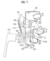
- FIGS. 7 and 8 illustrate diagrams showing different states of engagement of the latch with the latch board following operation of the door handle when the door is closed.
- the latch 242 is fitted rotatable around a rotation shaft 305, and the rotation shaft 305 has a rear end having a door handle fixed thereto.
- An upper side of the latch 242 and one side of the door panel 241 are connected with a spring 306.
- the door handle 243 is rotated in a clockwise direction in opening the door.
- the latch 242 When the door handle 243 is rotated in the clockwise direction, the latch 242 also rotates in the clockwise direction, and disengaged from the projection 201a. In this instance, a restoring force is provided from the spring 306 to the latch 242 for rotating the latch 242 in a counter clockwise direction.
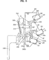
- FIG. 8 illustrates a diagram showing engagement of the latch with the latch board when the door is closed.
- the latch 242 when the door is closed, the latch 242 is inserted in the latch hole 209 as a sloped surface of the latch head 242a slides along an edge of the latch hole 209, and rotates in the counter clockwise direction by the spring 306 until the hook 242b on the latch 242 is hooked at the projection again, when the door is locked.
- the latch board 201 has three switches 'S' each of which is operable when an actuator thereon is pressed.
- the switches includes a monitor switch 'S3', a second safety switch 'S2', and a first safety switch 'S1'.
- the monitor switch 'S3' is in an upper part of the latch board 201
- the second safety switch 'S2' is in a lower part the latch board 201
- the first safety switch 'S1' is in a central part the latch board 201.
- the actuator 'A3' of the monitor switch 'S3' is positioned adjacent to the arm of the first lever L1, and the actuators A1 and A2 of the first safety switch 'S1' and the second safety switch S2 are positioned adjacent to arms of the second lever L2, respectively.
- the push bar 244 inserted through the bar hole 208 pushes a lower arm L12 of the first lever L1 downward, when the first lever L1 rotates in the counter clockwise direction until an upper arm L11 thereof presses an actuator 'A' on a bottom of the monitor switch 'S3'.
- arms of the second lever L2 move away from the actuators respectively.
- the first arm L21 positions over the actuator 'A1' of the first safety switch 'S1'
- the second arm L22 positions over the actuator 'A2' of the second safety switch 'S2
- the third arm L23 is held at the projection 201a on one side of the latch hole 209.
- the latch head 242a pushes the third arm L23 to rotate in the clockwise direction L23.
- the first arm L21 presses down the actuator 'A1' of the first safety switch S1
- the second arm L22 presses down the actuator 'A2' of the second safety switch S2.
- the latch board 201 in accordance with a first preferred embodiment of the present invention can operate three switches S1, S2, and S3 only with two levers L1, and L2. Moreover, since the levers L1 and L2 are restored by own gravity, respectively, no separate spring is required.
- Each of the switches has two holes in a diagonal direction, and the latch board 201 has fastening pins 381 and bosses (not shown) at positions corresponding to positions of the holes Sh.
- the fastening pins 381 and the bosses are inserted in the holes Sh in the switches, respectively.
- the switch 'S' is fastened to the latch board 201.
- the switches 'S' may be fastened by two in parallel, when the switches 'S' are fastened to the latch board 201 with screws 309 and fastening pin as long as a width of the switches overlapped in parallel.
- FIG. 9 illustrates a side section of a latch board in accordance with a second preferred embodiment of the present invention
- FIG. 10 illustrates a rear view of a latch board in accordance with a second preferred embodiment of the present invention.
- the latch board 301 is divided into a front surface part and a rear surface part by a board wall.
- the front surface part has a first lever L1, a second lever L2, a monitor switch S3, a first safety switch S1, and a second safety switch S2 fitted thereto, and the rear surface part has the other monitor switch S3' and the other first safety switch S1'.
- the other monitor switch S3' and the other first safety switch S1' may be substituted with switches having different functions, respectively.
- the levers 'L' are passed through the board wall 319.
- FIGS. 11 and 12 illustrate perspective views showing a first lever L1' and a second lever 'L2' to be fitted to a latch board in accordance with a second preferred embodiment of the present invention, respectively.
- the first lever L1' and the second lever L2' have extensions W1 and W2 passed through the board wall 319 respectively, and the latch board 301 has lever pass through holes 391, and 392 the extensions W1 and W2 pass therethrough. Actuators of the switches fitted parallel to each other are pressed at the same time with the extensions W1, and W2.
- two monitor switches S3, and S3', and actuators A3, and A3' thereof are fitted in parallel respectively, and the extension W1 pass through the lever pass through hole 391 so that the first lever L1' presses the two actuators at the same time.
- the push bar 144 presses the first lever L1' the extension W1 from the upper arm is rotated.
- the actuators A3, and A3' of the monitor switches S3 and S3' positioned in front and rear surfaces of the latch board 301 are pressed at the same time with the upper arm and the extension of the first lever L1'.
- the extension W2 from the second lever L2' also passes through the lever pass through hole 392 in the latch board 201.
- the latch 142 presses the second lever L2' the extension W2 from the second lever L2' rotates.
- the actuators A1, and A2 of the first safety switches S1, and S2 positioned on the front and rear surfaces of the latch board 301 are pressed at the same time by the arm and the extension of the second lever L2'.
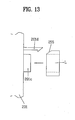
- FIG. 13 illustrates a structure employed in each of embodiments for holding a lever L1, L1', L2, or L2' on a board wall of a latch board.
- the lever L is rotatably fitted to a rotation shaft 201c of a latch board.
- the lever L is held with a hook 201d after the lever L is inserted in the rotation shaft 201c for preventing break away of the lever L from the rotation shaft 201c.
- the hook 201d deforms elastically, and after insertion of the lever 101c is finished, the hook 201 d is restored, to hold an upper part of the lever L.
- a sloped surface 55 is formed at the lever L in contact with the hook 201d. That is, since a head of the hook 201d slides along the sloped surface 255 when the hook 201d fastens the lever L, the lever L can be fitted to the latch board more stably without any damage to the lever L or the hook 201d.
- the rotation shaft 201c and the hook 201d are formed as one unit with the latch board 201 for simplifying an assembly structure of the latch board 201.
- FIG 14 illustrates a diagram of a pin formed at one side of a door as one unit with the door in accordance with a preferred embodiment of the present invention
- FIG. 15 illustrates a section of the pin.
- the horizontal member 250 has a pin 250a formed as one unit with the horizontal member 250 for serving as a rotation shaft of the door 114. Also, it is preferable that the horizontal member 250 is formed as one unit with the door 114.
- the pin 250a is formed as one unit with the horizontal member 250 at one side part of the horizontal member by pressing. Therefore, it is preferable that the horizontal member 250 of the door is formed of a metal for easy pressing. Since the pin 250a is formed as one unit with the horizontal member 250, fitting of the pin 250a is easy and damage to the pin 250a is prevented in comparison to a case the pin is fitted as a separate component.
- the door 114 is rotatably mounted on the frame 13.
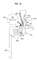
- FIG. 16 illustrates a side view of a latch assembly in accordance with a preferred embodiment of the present invention
- FIG. 17 illustrates a section of the fitting structure.
- the latch assembly includes a door panel 241, a push bar 244, a latch 242, a handle 243, a spring 306, and a fastening pin 218.
- the door panel 241 is provided to one side of the door.
- the push bar 244 is in an upper part of the door panel 241, and the latch 242 is in a lower part of the door panel 241.
- the handle 243 has one end connected to the latch 242.
- the spring 306 has one end connected to an upper part of the door panel 241, and the other end connected to a hook 242a on the latch 242, so that the spring 306 provides a restoring force for rotating the latch 242 in a counter clockwise direction.
- the latch 242 has an extension 242c in a lower part, and the door panel 241 has a projection 241a formed thereon. Since the extension 242c is held by the projection 241a at a desired angle, any further rotation of the latch 242 is prevented.
- the fastening pin 218 is fastened to the door panel, passing through the door handle 243 and the latch 242. According to this, the door handle 243 and the latch 242 turn around the fastening pin 218.
- the latch 242 and a link part 203 of the handle 243 are on the same rotation shaft, so that the handle 243 and the latch 242 rotate together.
- the latch 242 when the handle 243 is rotated in a clockwise direction for opening the door, the latch 242 also rotates in a clockwise direction. In this instance, the hook 242b at the end of the latch 242 is disengaged from the projection (reference numeral 201 in FIG. 7).
- the fastening pin 218 is fitted such that a head 218a thereof is clamped between the door panel 241 and the door 114, and the other end directed to an open surface of the door panel 241.
- the door panel 241 is fastened to one side of the door 114 rigidly with screws or the like.
- the microwave oven of the present invention has the following advantages.
- the restoration of the levers fitted to the door for the microwave oven of the present invention by gravity permits to dispense with springs, to reduce a number of required components.
- the formation of the pin, serving as a rotation shaft of the door, as one unit with the door permits to simplify an assembly process. Moreover, breakage of the pin taken place when the pin is formed separately can be prevented.
Landscapes
- Engineering & Computer Science (AREA)
- Physics & Mathematics (AREA)
- Electromagnetism (AREA)
- Chemical & Material Sciences (AREA)
- Combustion & Propulsion (AREA)
- Mechanical Engineering (AREA)
- General Engineering & Computer Science (AREA)
- Electric Ovens (AREA)
Abstract
Description
Claims (30)
- A door assembly for a microwave oven comprising:a door panel (241) at one side of a door and having a push bar (244) and a latch (242) both projected from one side thereof; anda latch board (201;301) including
levers (L1,L2;L1',L2') each fitted rotatable at contact with the latch (242) or the push bar (244), and
switches (S1,S2,S3;S1',S3') each operable at contact with the levers (L1,L2;L1',L2'). - The door assembly as claimed in claim 1, wherein at least one (L2,L2') of the levers (L1,L2;L1',L2') has at least three arms (L21,L22,L23).
- The door assembly as claimed in claim 1 or 2, wherein the levers include:a first lever (L1) for being brought into contact with the push bar (244), anda second lever (L2) for being brought into contact with the latch (242).
- The door assembly as claimed in claim 3, wherein the second lever (L2) includes:a third arm (L23) for being brought into contact with the latch (242), anda second arm (L22) and a first arm (L21) for operating the switches (S1,S2) respectively when the third arm (L23) is pushed amd rotated by the latch (242).
- The door assembly as claimed in claim 3 or 4, wherein the first lever (L1) includes:a second arm (L12) for being brought into contact with the push bar (244), anda first arm (L11) for operating the switch (S3) when the second arm (L12) is pushed and rotated by the push bar (244).
- The door assembly as claimed in any one of claims 1 to 5, wherein the door panel (241) is formed as one unit with the door.
- The door assembly as claimed in any one of claims 1 to 6, wherein the latch board (201) includes a push bar hole (208) and a latch hole (209) for inserting the push bar (244) and the latch (242), respectively.
- The door assembly as claimed in claim 7, wherein the latch (242) has a sloped surface at an end part (242a) for inserting the latch (242) into the latch hole (209) as the sloped surface slides into the latch hole (209).
- The door assembly as claimed in claim 7 or 8, wherein the latch hole (209) includes a projection (201a) on an inside edge for hooking the latch (242).
- The door assembly as claimed in claim 9, wherein one (L1) of the levers is held by an upper side of the projection (201a).
- The door assembly as claimed in any one of claims 1 to 10, further comprising a spring (306) having one end hooked at a hook at one side of the latch (242), and the other end held in an upper part of the door panel (241).
- The door assembly as claimed in claim 11, wherein the spring (306) provides a restoring force for rotating the latch (242) which pushes an arm (L23) of one (L1) of the levers.
- The door assembly as claimed in any one of claims 1 to 12, wherein the switches (S1,S2,S3) are fitted on a front surface and a rear surface of the latch board (201) in parallel.
- The door assembly as claimed in any one of claims 1 to 13, wherein the latch board (201) has fastening pins (381) and bosses, and the switches (S1,S2,S3) have holes (Sh) for inserting the fastening pins (381) and the bosses, whereby the switches (S1,S2,S3) are fastened to the latch board (201) by screws (309) fastened to the respective bosses.
- The door assembly as claimed in any one of claims 1 to 14, wherein the levers (L1,L2) are adapted to rotate to their original positions when the levers (L1,L2) are disengaged from the latch (242) or the push bar (244).
- The door assembly as claimed in claim 15, wherein the latch board (201) has stoppers (210) for holding the levers (L1,L2) at preset positions, respectively.
- The door assembly as claimed in any one of claims 1 to 16, wherein the levers (L1,L2) are fitted to rotation shafts (201c) projected from the latch board (201) respectively, and the levers (L1,L2) are fitted to the rotation shafts (201c) and held by hooks (201d), respectively.
- The door assembly as claimed in claim 17, wherein the levers (L1,L2) have a sloped surface (255) at a part at which the lever is brought into contact with the respective hook (201d) in fitting the lever to the respective rotation shaft (201c).
- The door assembly as claimed in claim 1, wherein said latch board (301) comprises a board wall (319) for dividing a front surface and a rear surface, and said switches (S1,S1',S2,S3,S3') are fitted on the front and rear surfaces of the board wall (319) in parallel.
- The door assembly as claimed in claim 19, wherein the board wall (319) has pass through holes (391,392) formed therein, and the levers (L1',L2') have extensions (W1,W2) rotatable along the pass through holes (391,392), respectively.
- The door assembly as claimed in claim 20, wherein the levers (L1',L2') are arranged so as to operate switches (S1,S2,S3) on the front surface respectively, and the extensions (W1,W2) are arranged so as to operate switches (S1',S3') on the rear surfaces respectively.
- The door assembly as claimed in claim 19, wherein the switches include a first safety switch, a second safety switch, and a monitor switch, and switches are fitted parallel to, and on opposite sides of the switches.
- A door assembly for a microwave oven comprising:horizontal members each extended from an upper part, or a lower part of an edge of the door;pins each formed as one unit with one of the horizontal members; andbrackets on a frame of the microwave oven, each having a hole for rotatably inserting the pin.
- The door assembly as claimed in claim 23, wherein the pin is a projection from the horizontal member formed by pressing.
- The door assembly as claimed in claim 23, wherein the horizontal members are formed as one unit with the door.
- A door assembly for a microwave oven comprising:a latch assembly including:a door panel (241) at one side of a door for the microwave oven,a push bar (244) projected from the door panel (241) toward a body,a latch (242) rotatably fitted to the door panel (241) spaced a distance away from the push bar (244),a spring (306) having one end held at an upper part of the door panel (241), and the other end connected to the latch (242), anda fastening pin fastened through the door panel (241) and the latch (242) to serve as a rotation shaft (305) of the latch (242), and
a latch board (201) including:levers (L1,L2) rotatable at contact with the latch (242) and the push bar (244) respectively, andswitches (S1,S2,S3) operable at contact with the levers (L1,L2) respectively. - The door assembly as claimed in claim 26, further comprising a handle (243) linked with the latch (242), and fitted rotatable around the fastening pin.
- The door assembly as claimed in claim 26 or 27, wherein the fastening pin has a head clamped between the door and the door panel (241).
- The door assembly as claimed in claim 26, 27 or 28, wherein the spring (306) provides a restoring force for rotating the latch (242) in one direction.
- The door assembly as claimed in claim 26, 27, 28 or 29, further comprising a,projection on one side part of the door panel for holding the latch such that the latch rotates no more than a desired angle.
Applications Claiming Priority (4)
| Application Number | Priority Date | Filing Date | Title |
|---|---|---|---|
| KR2003017195 | 2003-03-19 | ||
| KR10-2003-0017195A KR100531372B1 (en) | 2003-03-19 | 2003-03-19 | Latch & latchboard in microwave |
| KR1020030018449A KR20040083799A (en) | 2003-03-25 | 2003-03-25 | Latch assembly structure for Microwave oven |
| KR2003018449 | 2003-03-25 |
Publications (3)
| Publication Number | Publication Date |
|---|---|
| EP1469257A2 true EP1469257A2 (en) | 2004-10-20 |
| EP1469257A3 EP1469257A3 (en) | 2012-02-22 |
| EP1469257B1 EP1469257B1 (en) | 2015-01-28 |
Family
ID=32911523
Family Applications (1)
| Application Number | Title | Priority Date | Filing Date |
|---|---|---|---|
| EP20040002585 Expired - Lifetime EP1469257B1 (en) | 2003-03-19 | 2004-02-05 | Door assembly for microwave oven |
Country Status (4)
| Country | Link |
|---|---|
| US (1) | US7091458B2 (en) |
| EP (1) | EP1469257B1 (en) |
| CN (1) | CN1306217C (en) |
| CA (1) | CA2457276C (en) |
Cited By (3)
| Publication number | Priority date | Publication date | Assignee | Title |
|---|---|---|---|---|
| EP2408264A1 (en) * | 2004-12-14 | 2012-01-18 | Enodis Corporation | Impingement/ Convection/ Microwave Oven and Method |
| AU2012200169B2 (en) * | 2004-12-14 | 2014-01-30 | Enodis Corporation | Impingement / convection / microwave oven and method |
| WO2025132188A1 (en) | 2023-12-19 | 2025-06-26 | BSH Hausgeräte GmbH | Door locking means for a domestic appliance, domestic appliance, and method |
Families Citing this family (22)
| Publication number | Priority date | Publication date | Assignee | Title |
|---|---|---|---|---|
| KR100546902B1 (en) * | 2003-10-16 | 2006-01-26 | 엘지전자 주식회사 | Latch Board Structure of Microwave Oven |
| US20100193508A1 (en) * | 2009-02-02 | 2010-08-05 | Honeywell International Inc. | Microwave door interlock switch assembly |
| JP5403790B2 (en) * | 2009-02-06 | 2014-01-29 | パナソニック株式会社 | High frequency heating device |
| US20130069512A1 (en) * | 2011-09-19 | 2013-03-21 | General Electric Company | Actuated door opening mechanism for microwave and speedcooking products |
| CN103134091B (en) * | 2011-12-05 | 2016-06-29 | 乐金电子(天津)电器有限公司 | The interlock of microwave oven |
| US20140197161A1 (en) * | 2013-01-16 | 2014-07-17 | Standex International Corporation | Door switch apparatus for microwave ovens |
| CN104373976B (en) * | 2013-08-12 | 2017-05-03 | 广东美的厨房电器制造有限公司 | Household appliance |
| CA2878537C (en) * | 2015-01-19 | 2019-01-15 | Fabricant De Poeles International Inc. | Solid fuel burning stove and door locking assembly for a solid fuel burning stove |
| CN105889995B (en) * | 2016-06-12 | 2017-12-29 | 广东美的厨房电器制造有限公司 | Interlocking switch structure and micro-wave oven |
| KR102459278B1 (en) * | 2016-06-20 | 2022-10-26 | 엘지전자 주식회사 | Locker and Home Appliance comprising the same |
| KR102679174B1 (en) * | 2017-01-26 | 2024-06-28 | 삼성전자주식회사 | Cooking apparatus |
| AU2018295558B2 (en) * | 2017-07-06 | 2024-05-02 | Breville Pty Limited | A retractable door for an oven |
| US10834789B2 (en) | 2017-12-19 | 2020-11-10 | Whirlpool Corporation | Electronic door opening system |
| US11683866B2 (en) * | 2018-11-06 | 2023-06-20 | Guangdong Midea Kitchen Appliances Manufacturing Co., Ltd. | Microwave oven |
| KR102870113B1 (en) * | 2021-05-20 | 2025-10-15 | 삼성전자주식회사 | Cooking apparatus |
| WO2023178730A1 (en) * | 2022-03-21 | 2023-09-28 | 广东美的厨房电器制造有限公司 | Door lock structure, household appliance, and control method for household appliance |
| EP4365395A4 (en) * | 2022-06-01 | 2025-02-26 | Guangdong Midea Kitchen Appliances Manufacturing Co., Ltd. | Household appliance |
| CN114961443B (en) * | 2022-06-01 | 2023-12-19 | 广东美的厨房电器制造有限公司 | Interlocking device of microwave oven and microwave oven |
| EP4538486A1 (en) * | 2022-06-01 | 2025-04-16 | Guangdong Midea Kitchen Appliances Manufacturing Co., Ltd. | Interlocking device for microwave oven, microwave oven, and household appliance |
| CN114961444B (en) * | 2022-06-01 | 2023-11-24 | 广东美的厨房电器制造有限公司 | Interlocking device of microwave oven and microwave oven |
| JP7813199B2 (en) * | 2022-08-02 | 2026-02-12 | シャープ株式会社 | heating cooker |
| CN222164902U (en) * | 2023-12-29 | 2024-12-13 | 广东美的厨房电器制造有限公司 | Household appliance and interlocking structure |
Family Cites Families (14)
| Publication number | Priority date | Publication date | Assignee | Title |
|---|---|---|---|---|
| JPS5725047Y2 (en) * | 1977-11-16 | 1982-05-31 | ||
| JPS57129329A (en) * | 1981-02-02 | 1982-08-11 | Matsushita Electric Ind Co Ltd | High-frequency heating device |
| JPS59198620A (en) * | 1983-04-26 | 1984-11-10 | シャープ株式会社 | Switch mechanism of cooking device |
| JPS6136624A (en) * | 1985-03-25 | 1986-02-21 | Matsushita Electric Ind Co Ltd | High frequency heating device |
| US4663505A (en) * | 1986-05-22 | 1987-05-05 | Litton Systems, Inc. | Interlock switch base plate assembly |
| US4745250A (en) * | 1987-04-27 | 1988-05-17 | Litton Systems, Inc. | Interlock switch baseplate assembly |
| AU596039B2 (en) * | 1988-05-20 | 1990-04-12 | Kabushiki Kaisha Toshiba | Cooker |
| JPH09189423A (en) * | 1995-12-13 | 1997-07-22 | Daewoo Electronics Co Ltd | Button device for opening the door of microwave oven |
| US5672857A (en) * | 1996-04-26 | 1997-09-30 | Honeywell Inc. | Switch actuating mechanism for two sequentially activated switches |
| JP3653968B2 (en) * | 1998-01-28 | 2005-06-02 | 松下電器産業株式会社 | High frequency heating device |
| JP3663908B2 (en) * | 1998-05-21 | 2005-06-22 | 松下電器産業株式会社 | High frequency heating device |
| KR100285840B1 (en) * | 1998-07-23 | 2001-06-01 | 윤종용 | Microwave Door Locking Device |
| KR100306633B1 (en) * | 1998-11-11 | 2001-11-17 | 윤종용 | Microwave oven with conductive member to control power supply to high voltage transformer as door opens and closes |
| JP2002267177A (en) * | 2001-03-09 | 2002-09-18 | Matsushita Electric Ind Co Ltd | High frequency heating equipment |
-
2004
- 2004-02-05 EP EP20040002585 patent/EP1469257B1/en not_active Expired - Lifetime
- 2004-02-11 CA CA 2457276 patent/CA2457276C/en not_active Expired - Fee Related
- 2004-02-18 US US10/779,758 patent/US7091458B2/en not_active Expired - Fee Related
- 2004-03-19 CN CNB2004100301113A patent/CN1306217C/en not_active Expired - Fee Related
Cited By (3)
| Publication number | Priority date | Publication date | Assignee | Title |
|---|---|---|---|---|
| EP2408264A1 (en) * | 2004-12-14 | 2012-01-18 | Enodis Corporation | Impingement/ Convection/ Microwave Oven and Method |
| AU2012200169B2 (en) * | 2004-12-14 | 2014-01-30 | Enodis Corporation | Impingement / convection / microwave oven and method |
| WO2025132188A1 (en) | 2023-12-19 | 2025-06-26 | BSH Hausgeräte GmbH | Door locking means for a domestic appliance, domestic appliance, and method |
Also Published As
| Publication number | Publication date |
|---|---|
| EP1469257A3 (en) | 2012-02-22 |
| EP1469257B1 (en) | 2015-01-28 |
| US20040182856A1 (en) | 2004-09-23 |
| CA2457276A1 (en) | 2004-09-19 |
| CN1306217C (en) | 2007-03-21 |
| CN1532459A (en) | 2004-09-29 |
| US7091458B2 (en) | 2006-08-15 |
| CA2457276C (en) | 2010-05-04 |
Similar Documents
| Publication | Publication Date | Title |
|---|---|---|
| EP1469257B1 (en) | Door assembly for microwave oven | |
| US6079756A (en) | Oven door latch | |
| US6390518B1 (en) | Latching mechanism for an appliance door | |
| US4542269A (en) | Cooking appliance with switching assembly | |
| CN102459794A (en) | Sliding and tilting door assembly | |
| EP3560288B1 (en) | Cooking apparatus | |
| US20070296224A1 (en) | Motorized oven lock with hidden latch | |
| US6893061B2 (en) | Methods and apparatus for securing a dishwasher door | |
| US4672160A (en) | Door safety switch-lock assembly for an electrical apparatus | |
| US7225804B2 (en) | Motor driven oven door latch | |
| CA2003122C (en) | Cabinet for cooking appliances | |
| US7956304B2 (en) | Combination switch | |
| US6863316B2 (en) | Door latch mechanism and associated components for a self-cleaning oven | |
| KR850001377Y1 (en) | Opening and shutting device for oven door | |
| US6601882B1 (en) | Door latch mechanism and associated components for a self-cleaning oven | |
| KR100531372B1 (en) | Latch & latchboard in microwave | |
| US6852961B2 (en) | High frequency heating apparatus provided with a switch attachment mechansm capable of covering at least one switch from outside | |
| KR100516660B1 (en) | Door interlock system of electric oven range | |
| KR970003074Y1 (en) | Micro Switch Driver of Microwave Oven | |
| KR102767616B1 (en) | A push door-lock equipment | |
| EP4464232B1 (en) | Driving device and electrical device comprising same | |
| KR102693537B1 (en) | An auto-open door-lock equipment | |
| KR102767611B1 (en) | An auto-open door-lock equipment | |
| JPS58110928A (en) | Microwave heating apparatus | |
| CN121630158A (en) | Door lock devices and electrical equipment |
Legal Events
| Date | Code | Title | Description |
|---|---|---|---|
| PUAI | Public reference made under article 153(3) epc to a published international application that has entered the european phase |
Free format text: ORIGINAL CODE: 0009012 |
|
| 17P | Request for examination filed |
Effective date: 20040205 |
|
| AK | Designated contracting states |
Kind code of ref document: A2 Designated state(s): AT BE BG CH CY CZ DE DK EE ES FI FR GB GR HU IE IT LI LU MC NL PT RO SE SI SK TR |
|
| AX | Request for extension of the european patent |
Extension state: AL LT LV MK |
|
| PUAL | Search report despatched |
Free format text: ORIGINAL CODE: 0009013 |
|
| AK | Designated contracting states |
Kind code of ref document: A3 Designated state(s): AT BE BG CH CY CZ DE DK EE ES FI FR GB GR HU IE IT LI LU MC NL PT RO SE SI SK TR |
|
| AX | Request for extension of the european patent |
Extension state: AL LT LV MK |
|
| RIC1 | Information provided on ipc code assigned before grant |
Ipc: H05B 6/64 20060101ALI20120119BHEP Ipc: F24C 15/02 20060101AFI20120119BHEP |
|
| AKX | Designation fees paid |
Designated state(s): DE FR GB IT NL |
|
| 17Q | First examination report despatched |
Effective date: 20131206 |
|
| GRAP | Despatch of communication of intention to grant a patent |
Free format text: ORIGINAL CODE: EPIDOSNIGR1 |
|
| INTG | Intention to grant announced |
Effective date: 20140909 |
|
| GRAS | Grant fee paid |
Free format text: ORIGINAL CODE: EPIDOSNIGR3 |
|
| GRAP | Despatch of communication of intention to grant a patent |
Free format text: ORIGINAL CODE: EPIDOSNIGR1 |
|
| GRAA | (expected) grant |
Free format text: ORIGINAL CODE: 0009210 |
|
| INTG | Intention to grant announced |
Effective date: 20141216 |
|
| AK | Designated contracting states |
Kind code of ref document: B1 Designated state(s): DE FR GB IT NL |
|
| REG | Reference to a national code |
Ref country code: GB Ref legal event code: FG4D |
|
| REG | Reference to a national code |
Ref country code: DE Ref legal event code: R096 Ref document number: 602004046571 Country of ref document: DE Effective date: 20150319 |
|
| REG | Reference to a national code |
Ref country code: NL Ref legal event code: VDEP Effective date: 20150128 |
|
| PG25 | Lapsed in a contracting state [announced via postgrant information from national office to epo] |
Ref country code: NL Free format text: LAPSE BECAUSE OF FAILURE TO SUBMIT A TRANSLATION OF THE DESCRIPTION OR TO PAY THE FEE WITHIN THE PRESCRIBED TIME-LIMIT Effective date: 20150128 |
|
| REG | Reference to a national code |
Ref country code: DE Ref legal event code: R097 Ref document number: 602004046571 Country of ref document: DE |
|
| PLBE | No opposition filed within time limit |
Free format text: ORIGINAL CODE: 0009261 |
|
| STAA | Information on the status of an ep patent application or granted ep patent |
Free format text: STATUS: NO OPPOSITION FILED WITHIN TIME LIMIT |
|
| GBPC | Gb: european patent ceased through non-payment of renewal fee |
Effective date: 20150428 |
|
| PG25 | Lapsed in a contracting state [announced via postgrant information from national office to epo] |
Ref country code: IT Free format text: LAPSE BECAUSE OF FAILURE TO SUBMIT A TRANSLATION OF THE DESCRIPTION OR TO PAY THE FEE WITHIN THE PRESCRIBED TIME-LIMIT Effective date: 20150128 |
|
| 26N | No opposition filed |
Effective date: 20151029 |
|
| REG | Reference to a national code |
Ref country code: FR Ref legal event code: ST Effective date: 20151210 |
|
| PG25 | Lapsed in a contracting state [announced via postgrant information from national office to epo] |
Ref country code: GB Free format text: LAPSE BECAUSE OF NON-PAYMENT OF DUE FEES Effective date: 20150428 |
|
| PG25 | Lapsed in a contracting state [announced via postgrant information from national office to epo] |
Ref country code: FR Free format text: LAPSE BECAUSE OF NON-PAYMENT OF DUE FEES Effective date: 20150330 |
|
| PGFP | Annual fee paid to national office [announced via postgrant information from national office to epo] |
Ref country code: DE Payment date: 20180105 Year of fee payment: 15 |
|
| REG | Reference to a national code |
Ref country code: DE Ref legal event code: R119 Ref document number: 602004046571 Country of ref document: DE |
|
| PG25 | Lapsed in a contracting state [announced via postgrant information from national office to epo] |
Ref country code: DE Free format text: LAPSE BECAUSE OF NON-PAYMENT OF DUE FEES Effective date: 20190903 |