EP1469165A1 - Réduction de jeux dans une turbine à gaz - Google Patents
Réduction de jeux dans une turbine à gaz Download PDFInfo
- Publication number
- EP1469165A1 EP1469165A1 EP04290819A EP04290819A EP1469165A1 EP 1469165 A1 EP1469165 A1 EP 1469165A1 EP 04290819 A EP04290819 A EP 04290819A EP 04290819 A EP04290819 A EP 04290819A EP 1469165 A1 EP1469165 A1 EP 1469165A1
- Authority
- EP
- European Patent Office
- Prior art keywords
- gas turbine
- heels
- turbine according
- blades
- casing
- Prior art date
- Legal status (The legal status is an assumption and is not a legal conclusion. Google has not performed a legal analysis and makes no representation as to the accuracy of the status listed.)
- Granted
Links
- 239000000463 material Substances 0.000 claims abstract description 17
- 238000001816 cooling Methods 0.000 claims description 4
- 239000000919 ceramic Substances 0.000 claims description 3
- 238000004026 adhesive bonding Methods 0.000 claims description 2
- 230000002787 reinforcement Effects 0.000 claims description 2
- 230000002093 peripheral effect Effects 0.000 abstract description 8
- 230000006866 deterioration Effects 0.000 description 2
- 230000006978 adaptation Effects 0.000 description 1
- 230000007547 defect Effects 0.000 description 1
- 239000000428 dust Substances 0.000 description 1
- 238000010410 dusting Methods 0.000 description 1
- 230000014759 maintenance of location Effects 0.000 description 1
- 239000002184 metal Substances 0.000 description 1
- 230000000717 retained effect Effects 0.000 description 1
- 238000007789 sealing Methods 0.000 description 1
- 210000003462 vein Anatomy 0.000 description 1
Images


Classifications
-
- F—MECHANICAL ENGINEERING; LIGHTING; HEATING; WEAPONS; BLASTING
- F01—MACHINES OR ENGINES IN GENERAL; ENGINE PLANTS IN GENERAL; STEAM ENGINES
- F01D—NON-POSITIVE DISPLACEMENT MACHINES OR ENGINES, e.g. STEAM TURBINES
- F01D5/00—Blades; Blade-carrying members; Heating, heat-insulating, cooling or antivibration means on the blades or the members
- F01D5/12—Blades
- F01D5/14—Form or construction
- F01D5/20—Specially-shaped blade tips to seal space between tips and stator
-
- F—MECHANICAL ENGINEERING; LIGHTING; HEATING; WEAPONS; BLASTING
- F01—MACHINES OR ENGINES IN GENERAL; ENGINE PLANTS IN GENERAL; STEAM ENGINES
- F01D—NON-POSITIVE DISPLACEMENT MACHINES OR ENGINES, e.g. STEAM TURBINES
- F01D5/00—Blades; Blade-carrying members; Heating, heat-insulating, cooling or antivibration means on the blades or the members
- F01D5/12—Blades
- F01D5/28—Selecting particular materials; Particular measures relating thereto; Measures against erosion or corrosion
- F01D5/284—Selection of ceramic materials
Definitions
- the invention essentially relates to means for reducing clearances between the tops of the movable blades and the internal surface of the housing a gas turbine, such as a high pressure turbine for a aircraft engine.
- heels peripherals at the top of the blades to limit radial clearances between the tops of the blades and a layer of abradable material carried by a ring fixed to the turbine housing.
- These heels may include circumferential ribs or wipers which are substantially in contact abradable material to ensure an axial seal between the casing and the tops of the moving blades.
- this radial clearance can vary locally between a value minimum and a maximum value, following an ovalization of the casing, a difference in the height of the blades, a lack of concentricity between the casing and turbine wheel, etc ...
- the object of the invention is in particular to provide a simple solution, satisfactory and economical to these problems.
- a gas turbine in particular for an engine. aircraft, comprising a turbine wheel rotatably mounted in a casing and carrying vanes whose vertices are at a radial distance small of an internal surface of the casing, and means for reducing clearances between the tips of the blades and the inner surface of the housing, characterized in that these play reduction means include heels mounted radially sliding at the top of the blades and guided in an annular groove in the housing.
- the heels are automatically biased towards the inner surface casing by centrifugal forces without exerting any force on the vanes wheel. This avoids the mechanical vibration problems encountered in moving blade turbines with fixed peripheral heels and the performance of the turbine is increased by eliminating the clearances radial between the tips of the blades and the inner surface of the housing.
- the heels are in lightweight and resistant to wear and high temperature material, material preferably being a ceramic.
- the heels above each have a curved plate intended to extend the along the inside surface of the housing.
- This curved plate has a surface larger than that of the top of the blade on which it is mounted, which further improves the sealing axial above between the tips of the blades and the inner surface of the casing.
- At least two parallel ribs circumferential wipers are presented by the face of this plate facing the internal face of the housing.
- each heel aforementioned is at least partially fitted into a bathtub formed at dawn summit.
- each heel above is fitted on the top of dawn.
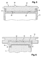
- the invention proposes, as shown in FIGS. 3 to 5, to mount a radially sliding peripheral heel 26 at the top of dawn 10, this peripheral heel 26 being partially inserted or housed in the bath 20 at the top of dawn 10.
- the heel 26 mounted at the end of the blade 10 is partially housed and guided in an annular groove or groove 34 in the ring 16, at the bottom of which is arranged the layer 18 of abradable material.
- This montage holds the heel 30 in place at the end of the blade 10, both in the direction of axial than in radial direction.
- the heels 26 are rotated around of the axis of the turbine with the blades 10 and are subjected to forces centrifugals which apply them to the layer 18 of abradable material.
- the cooling air of the blade 10 which leaves through the dusting orifices formed in the bottom of the bath 20, circulates in passages which are formed between the heel 26 and the side walls 36 of the bath and thus contributes to the cooling of these walls.
- the plates 30 forming the radially outer parts of the heels 26 may have a greater or lesser extent relative to the dimensions of the tips of the blades 10 and, if necessary, these plates 30 may include a reinforcement, for example metallic, of stiffening.
- the heels 26 can be kept on the vertices of the blades by gluing or by a link such as a rod or a strapping, surrounding the heels 26 and the crown of blades.
Landscapes
- Engineering & Computer Science (AREA)
- Mechanical Engineering (AREA)
- General Engineering & Computer Science (AREA)
- Chemical & Material Sciences (AREA)
- Ceramic Engineering (AREA)
- Materials Engineering (AREA)
- Turbine Rotor Nozzle Sealing (AREA)
Abstract
Description
- la figure 1 est une vue schématique partielle en coupe axiale représentant le jeu radial entre le sommet d'une aube mobile et la surface cylindrique interne d'un carter de turbine ;
- la figure 2 est une vue de dessus du sommet de l'aube de la figure 1 ;
- la figure 3 est une vue schématique partielle en coupe axiale d'un premier mode de réalisation de l'invention ;
- la figure 4 est une vue de dessus du sommet de l'aube de la figure 3 :
- la figure 5 est une vue schématique partielle en coupe axiale à plus grande échelle du sommet de l'aube des figures 3 et 4 ;
- la figure 6 est une vue schématique partielle en coupe axiale d'une variante de réalisation de l'invention.
Claims (13)
- Turbine à gaz, en particulier pour moteur d'aéronef, comprenant une roue montée en rotation dans un carter (14,16) et portant des aubes (10) dont les sommets sont à une distance radiale faible d'une surface intérieure du carter, et des moyens de réduction des jeux entre les sommets des aubes et la surface intérieure du carter, caractérisée en ce que les moyens de réduction des jeux comprennent des talons (26) montés radialement coulissants au sommet des aubes (10) et guidés dans une rainure annulaire (34) du carter (14, 16).
- Turbine à gaz selon la revendication 1, caractérisée en ce que les talons (26) sont en matériau léger et résistant à l'usure et aux températures élevées.
- Turbine à gaz selon la revendication 1 ou 2, caractérisée en ce que les talons (26) sont en céramique.
- Turbine à gaz selon l'une des revendications précédentes, caractérisée en ce que les talons (26) comprennent des parties radialement externes (30) en forme de plaques incurvées, destinées à s'étendre le long de la surface intérieure du carter.
- Turbine à gaz selon la revendication 4, caractérisée en ce que la partie radialement externe (30) en forme de plaque des talons (26) comprend une armature de rigidification.
- Turbine à gaz selon l'une des revendications précédentes, caractérisée en ce que chaque talon comporte des nervures parallèles circonférentielles (32) formant léchettes sur sa face tournée vers la surface intérieure du carter.
- Turbine à gaz selon l'une des revendications précédentes, caractérisée en ce que la surface intérieure du carter en regard des talons (26) comprend une couche (18) de matériau abradable.
- Turbine à gaz selon l'une des revendications précédentes, caractérisée en ce que les talons (26) sont emboítés sur les sommets des aubes (10).
- Turbine à gaz, en particulier à gaz selon l'une des revendications 1 à 7, caractérisée en ce que les talons (26) sont au moins partiellement insérés dans des baignoires (20) formées au sommet des aubes (10).
- Turbine à gaz selon la revendication 9, caractérisée en ce que les talons (26) délimitent avec les parois (36) des baignoires (20), des passages de circulation d'air de refroidissement, alimentés par des canaux débouchant dans le fond des baignoires.
- Turbine à gaz selon l'une des revendications précédentes, caractérisée en ce qu'elle comprend des moyens (20,34,38) de maintien axial et radial des talons (26) sur les sommets des aubes (10).
- Turbine à gaz selon l'une des revendications précédentes, caractérisée en ce que, pour le montage, les talons (26) sont maintenus sur les sommets des aubes par collage ou par un lien entourant les aubes.
- Turbine à gaz selon l'une des revendications précédentes, caractérisée en ce que la surface intérieure du carter en regard des talons (26) est cylindrique divergente ou à section constante.
Applications Claiming Priority (2)
| Application Number | Priority Date | Filing Date | Title |
|---|---|---|---|
| FR0304736 | 2003-04-16 | ||
| FR0304736A FR2853931A1 (fr) | 2003-04-16 | 2003-04-16 | Reduction de jeux dans une turbine a gaz |
Publications (2)
| Publication Number | Publication Date |
|---|---|
| EP1469165A1 true EP1469165A1 (fr) | 2004-10-20 |
| EP1469165B1 EP1469165B1 (fr) | 2006-10-18 |
Family
ID=32893372
Family Applications (1)
| Application Number | Title | Priority Date | Filing Date |
|---|---|---|---|
| EP04290819A Expired - Lifetime EP1469165B1 (fr) | 2003-04-16 | 2004-03-26 | Réduction de jeux dans une turbine à gaz |
Country Status (6)
| Country | Link |
|---|---|
| US (1) | US6976824B2 (fr) |
| EP (1) | EP1469165B1 (fr) |
| CA (1) | CA2463182C (fr) |
| DE (1) | DE602004002798T2 (fr) |
| ES (1) | ES2274395T3 (fr) |
| FR (1) | FR2853931A1 (fr) |
Cited By (6)
| Publication number | Priority date | Publication date | Assignee | Title |
|---|---|---|---|---|
| WO2006062451A1 (fr) * | 2004-12-08 | 2006-06-15 | Volvo Aero Corporation | Roue pour machine a flux rotatif |
| RU2380545C2 (ru) * | 2004-12-08 | 2010-01-27 | Вольво Аэро Корпорейшн | Рабочее колесо вращающейся проточной машины и авиационный двигатель |
| FR2940352A1 (fr) * | 2008-12-23 | 2010-06-25 | Snecma | Roue mobile de turbomachine a aubes en materiau composite munies de lechettes metalliques. |
| FR3025555A1 (fr) * | 2014-09-09 | 2016-03-11 | Snecma | Aube de turbine et turbomachine |
| FR3085712A1 (fr) * | 2018-09-06 | 2020-03-13 | Safran Aircraft Engines | Aube de roue mobile pour turbomachine d'aeronef, presentant un talon decouple de la pale de l'aube |
| FR3118105A1 (fr) * | 2020-12-17 | 2022-06-24 | Safran Aircraft Engines | Ensemble rotatif comportant un disque aubagé entouré par un anneau |
Families Citing this family (9)
| Publication number | Priority date | Publication date | Assignee | Title |
|---|---|---|---|---|
| US8434997B2 (en) * | 2007-08-22 | 2013-05-07 | United Technologies Corporation | Gas turbine engine case for clearance control |
| US9133726B2 (en) * | 2007-09-17 | 2015-09-15 | United Technologies Corporation | Seal for gas turbine engine component |
| US8585356B2 (en) * | 2010-03-23 | 2013-11-19 | Siemens Energy, Inc. | Control of blade tip-to-shroud leakage in a turbine engine by directed plasma flow |
| US8500404B2 (en) | 2010-04-30 | 2013-08-06 | Siemens Energy, Inc. | Plasma actuator controlled film cooling |
| US9938845B2 (en) * | 2013-02-26 | 2018-04-10 | Rolls-Royce Corporation | Gas turbine engine vane end devices |
| US9771870B2 (en) | 2014-03-04 | 2017-09-26 | Rolls-Royce North American Technologies Inc. | Sealing features for a gas turbine engine |
| JP6595926B2 (ja) * | 2016-02-02 | 2019-10-23 | 三菱日立パワーシステムズ株式会社 | 回転機械 |
| US10487679B2 (en) * | 2017-07-17 | 2019-11-26 | United Technologies Corporation | Method and apparatus for sealing components of a gas turbine engine with a dielectric barrier discharge plasma actuator |
| KR101974736B1 (ko) * | 2017-09-27 | 2019-05-02 | 두산중공업 주식회사 | 블레이드의 실링구조와 이를 포함하는 로터 및 가스터빈 |
Citations (8)
| Publication number | Priority date | Publication date | Assignee | Title |
|---|---|---|---|---|
| US3117716A (en) * | 1963-04-10 | 1964-01-14 | Bell Aerospace Corp | Ducted rotor |
| GB1107024A (en) * | 1965-11-04 | 1968-03-20 | Parsons C A & Co Ltd | Improvements in and relating to blades for turbo-machines |
| FR2502242A1 (fr) * | 1981-03-20 | 1982-09-24 | Gen Electric | Embout rapporte pour aube de rotor |
| GB2106997A (en) * | 1981-10-01 | 1983-04-20 | Rolls Royce | Vibration damped rotor blade for a turbomachine |
| JPS62142805A (ja) * | 1985-12-18 | 1987-06-26 | Toshiba Corp | 軸流流体機械の動翼 |
| FR2640701A1 (fr) * | 1988-12-19 | 1990-06-22 | Mtu Muenchen Gmbh | Roue mobile de compresseur |
| DE19531561A1 (de) * | 1995-08-28 | 1997-03-06 | Abb Research Ltd | Versteifungen für Turbinenschaufeln |
| EP1267037A2 (fr) * | 2001-04-16 | 2002-12-18 | United Technologies Corporation | Elément de recouvrement creux refroidis de l'extrémité d'une aube de turbine |
Family Cites Families (3)
| Publication number | Priority date | Publication date | Assignee | Title |
|---|---|---|---|---|
| US3547455A (en) * | 1969-05-02 | 1970-12-15 | Gen Electric | Rotary seal including organic abradable material |
| US4336276A (en) * | 1980-03-30 | 1982-06-22 | The United States Of America As Represented By The Administrator Of The National Aeronautics And Space Administration | Fully plasma-sprayed compliant backed ceramic turbine seal |
| US4424001A (en) * | 1981-12-04 | 1984-01-03 | Westinghouse Electric Corp. | Tip structure for cooled turbine rotor blade |
-
2003
- 2003-04-16 FR FR0304736A patent/FR2853931A1/fr active Pending
-
2004
- 2004-03-26 EP EP04290819A patent/EP1469165B1/fr not_active Expired - Lifetime
- 2004-03-26 ES ES04290819T patent/ES2274395T3/es not_active Expired - Lifetime
- 2004-03-26 DE DE602004002798T patent/DE602004002798T2/de not_active Expired - Lifetime
- 2004-04-14 CA CA2463182A patent/CA2463182C/fr not_active Expired - Lifetime
- 2004-04-16 US US10/825,320 patent/US6976824B2/en not_active Expired - Fee Related
Patent Citations (8)
| Publication number | Priority date | Publication date | Assignee | Title |
|---|---|---|---|---|
| US3117716A (en) * | 1963-04-10 | 1964-01-14 | Bell Aerospace Corp | Ducted rotor |
| GB1107024A (en) * | 1965-11-04 | 1968-03-20 | Parsons C A & Co Ltd | Improvements in and relating to blades for turbo-machines |
| FR2502242A1 (fr) * | 1981-03-20 | 1982-09-24 | Gen Electric | Embout rapporte pour aube de rotor |
| GB2106997A (en) * | 1981-10-01 | 1983-04-20 | Rolls Royce | Vibration damped rotor blade for a turbomachine |
| JPS62142805A (ja) * | 1985-12-18 | 1987-06-26 | Toshiba Corp | 軸流流体機械の動翼 |
| FR2640701A1 (fr) * | 1988-12-19 | 1990-06-22 | Mtu Muenchen Gmbh | Roue mobile de compresseur |
| DE19531561A1 (de) * | 1995-08-28 | 1997-03-06 | Abb Research Ltd | Versteifungen für Turbinenschaufeln |
| EP1267037A2 (fr) * | 2001-04-16 | 2002-12-18 | United Technologies Corporation | Elément de recouvrement creux refroidis de l'extrémité d'une aube de turbine |
Non-Patent Citations (1)
| Title |
|---|
| PATENT ABSTRACTS OF JAPAN vol. 011, no. 368 (M - 647) 2 December 1987 (1987-12-02) * |
Cited By (8)
| Publication number | Priority date | Publication date | Assignee | Title |
|---|---|---|---|---|
| WO2006062451A1 (fr) * | 2004-12-08 | 2006-06-15 | Volvo Aero Corporation | Roue pour machine a flux rotatif |
| RU2380545C2 (ru) * | 2004-12-08 | 2010-01-27 | Вольво Аэро Корпорейшн | Рабочее колесо вращающейся проточной машины и авиационный двигатель |
| US7798778B2 (en) | 2004-12-08 | 2010-09-21 | Volvo Aero Corporation | Wheel for a rotating flow machine |
| FR2940352A1 (fr) * | 2008-12-23 | 2010-06-25 | Snecma | Roue mobile de turbomachine a aubes en materiau composite munies de lechettes metalliques. |
| US8870531B2 (en) | 2008-12-23 | 2014-10-28 | Snecma | Turbomachine rotor having blades of composite material provided with metal labyrinth teeth |
| FR3025555A1 (fr) * | 2014-09-09 | 2016-03-11 | Snecma | Aube de turbine et turbomachine |
| FR3085712A1 (fr) * | 2018-09-06 | 2020-03-13 | Safran Aircraft Engines | Aube de roue mobile pour turbomachine d'aeronef, presentant un talon decouple de la pale de l'aube |
| FR3118105A1 (fr) * | 2020-12-17 | 2022-06-24 | Safran Aircraft Engines | Ensemble rotatif comportant un disque aubagé entouré par un anneau |
Also Published As
| Publication number | Publication date |
|---|---|
| US20050008481A1 (en) | 2005-01-13 |
| ES2274395T3 (es) | 2007-05-16 |
| CA2463182A1 (fr) | 2004-10-16 |
| CA2463182C (fr) | 2011-09-27 |
| DE602004002798T2 (de) | 2007-08-23 |
| US6976824B2 (en) | 2005-12-20 |
| EP1469165B1 (fr) | 2006-10-18 |
| DE602004002798D1 (de) | 2006-11-30 |
| FR2853931A1 (fr) | 2004-10-22 |
Similar Documents
| Publication | Publication Date | Title |
|---|---|---|
| EP1469165B1 (fr) | Réduction de jeux dans une turbine à gaz | |
| CA2752487C (fr) | Temoin d'erosion pour roue de compresseur | |
| FR2872870A1 (fr) | Commande de jeu de pale | |
| CA2598532C (fr) | Aube de rotor d'une turbomachine | |
| FR2899274A1 (fr) | Dispositif de fixation de secteurs d'anneau autour d'une roue de turbine d'une turbomachine | |
| WO2010072968A1 (fr) | Roue mobile de turbomachine a aubes en materiau composite munie d'un anneau ressort | |
| EP3421730B1 (fr) | Turbine pour turbomachine avec anneau d'étanchéité comportant deux parties | |
| EP2096270A1 (fr) | Jonc annulaire fendu pour piece tournante de turbomachine | |
| FR3085712A1 (fr) | Aube de roue mobile pour turbomachine d'aeronef, presentant un talon decouple de la pale de l'aube | |
| EP3880939B1 (fr) | Étanchéité entre une roue mobile et un distributeur d'une turbomachine | |
| EP3201438B1 (fr) | Aube mobile de turbomachine, comprenant un ergot engageant une entaille de blocage d'un disque de rotor | |
| FR3058756A1 (fr) | Turbine pour turbomachine | |
| FR2978793A1 (fr) | Rotor de turbine pour une turbomachine | |
| FR3058755A1 (fr) | Turbine pour turbomachine | |
| FR2945331A1 (fr) | Virole pour stator de turbomoteur d'aeronef a fentes de dechargement mecanique d'aubes. | |
| FR3066533B1 (fr) | Ensemble d'etancheite pour une turbomachine | |
| WO2023041868A1 (fr) | Aube mobile pour turbine de turbomachine, comprenant une échasse équipée d'excroissances de retenue radiale de l'aube | |
| FR3137122A1 (fr) | Ensemble aubagé à liaison inter-plateformes par organe de friction | |
| FR3079553A1 (fr) | Ensemble pour turbomachine | |
| FR3075252A1 (fr) | Ensemble d'etancheite | |
| EP4684113A1 (fr) | Joint d'etancheite pour turbomachine | |
| FR3158755A1 (fr) | Ensemble d’étanchéité amélioré pour turbine de turbomachine | |
| FR3126022A1 (fr) | Ensemble pour turbomachine d’aeronef comprenant une anneau de recouvrement pour l’isolement d’organes de fixation mecanique vis-a-vis d’un flux d’air | |
| FR3092861A1 (fr) | Ensemble de turbomachine comportant un taquet sur un jonc d'etancheite | |
| EP4234886A2 (fr) | Aube mobile pour une roue d'une turbomachine |
Legal Events
| Date | Code | Title | Description |
|---|---|---|---|
| PUAI | Public reference made under article 153(3) epc to a published international application that has entered the european phase |
Free format text: ORIGINAL CODE: 0009012 |
|
| AK | Designated contracting states |
Kind code of ref document: A1 Designated state(s): AT BE BG CH CY CZ DE DK EE ES FI FR GB GR HU IE IT LI LU MC NL PL PT RO SE SI SK TR |
|
| AX | Request for extension of the european patent |
Extension state: AL HR LT LV MK |
|
| 17P | Request for examination filed |
Effective date: 20050214 |
|
| AKX | Designation fees paid |
Designated state(s): DE ES FR GB IT SE |
|
| RAP1 | Party data changed (applicant data changed or rights of an application transferred) |
Owner name: SNECMA |
|
| GRAP | Despatch of communication of intention to grant a patent |
Free format text: ORIGINAL CODE: EPIDOSNIGR1 |
|
| GRAS | Grant fee paid |
Free format text: ORIGINAL CODE: EPIDOSNIGR3 |
|
| GRAA | (expected) grant |
Free format text: ORIGINAL CODE: 0009210 |
|
| AK | Designated contracting states |
Kind code of ref document: B1 Designated state(s): DE ES FR GB IT SE |
|
| REG | Reference to a national code |
Ref country code: GB Ref legal event code: FG4D Free format text: NOT ENGLISH |
|
| REF | Corresponds to: |
Ref document number: 602004002798 Country of ref document: DE Date of ref document: 20061130 Kind code of ref document: P |
|
| GBT | Gb: translation of ep patent filed (gb section 77(6)(a)/1977) |
Effective date: 20061220 |
|
| REG | Reference to a national code |
Ref country code: SE Ref legal event code: TRGR |
|
| REG | Reference to a national code |
Ref country code: ES Ref legal event code: FG2A Ref document number: 2274395 Country of ref document: ES Kind code of ref document: T3 |
|
| PLBE | No opposition filed within time limit |
Free format text: ORIGINAL CODE: 0009261 |
|
| STAA | Information on the status of an ep patent application or granted ep patent |
Free format text: STATUS: NO OPPOSITION FILED WITHIN TIME LIMIT |
|
| 26N | No opposition filed |
Effective date: 20070719 |
|
| PGFP | Annual fee paid to national office [announced via postgrant information from national office to epo] |
Ref country code: ES Payment date: 20120309 Year of fee payment: 9 |
|
| REG | Reference to a national code |
Ref country code: ES Ref legal event code: FD2A Effective date: 20140613 |
|
| PG25 | Lapsed in a contracting state [announced via postgrant information from national office to epo] |
Ref country code: ES Free format text: LAPSE BECAUSE OF NON-PAYMENT OF DUE FEES Effective date: 20130327 |
|
| REG | Reference to a national code |
Ref country code: FR Ref legal event code: PLFP Year of fee payment: 13 |
|
| REG | Reference to a national code |
Ref country code: FR Ref legal event code: PLFP Year of fee payment: 14 |
|
| PGFP | Annual fee paid to national office [announced via postgrant information from national office to epo] |
Ref country code: SE Payment date: 20170224 Year of fee payment: 14 Ref country code: DE Payment date: 20170222 Year of fee payment: 14 |
|
| PGFP | Annual fee paid to national office [announced via postgrant information from national office to epo] |
Ref country code: GB Payment date: 20170224 Year of fee payment: 14 |
|
| PGFP | Annual fee paid to national office [announced via postgrant information from national office to epo] |
Ref country code: IT Payment date: 20170221 Year of fee payment: 14 |
|
| REG | Reference to a national code |
Ref country code: FR Ref legal event code: CD Owner name: SAFRAN AIRCRAFT ENGINES Effective date: 20170713 |
|
| REG | Reference to a national code |
Ref country code: FR Ref legal event code: PLFP Year of fee payment: 15 |
|
| REG | Reference to a national code |
Ref country code: DE Ref legal event code: R119 Ref document number: 602004002798 Country of ref document: DE |
|
| PG25 | Lapsed in a contracting state [announced via postgrant information from national office to epo] |
Ref country code: SE Free format text: LAPSE BECAUSE OF NON-PAYMENT OF DUE FEES Effective date: 20180327 |
|
| GBPC | Gb: european patent ceased through non-payment of renewal fee |
Effective date: 20180326 |
|
| PG25 | Lapsed in a contracting state [announced via postgrant information from national office to epo] |
Ref country code: DE Free format text: LAPSE BECAUSE OF NON-PAYMENT OF DUE FEES Effective date: 20181002 |
|
| PG25 | Lapsed in a contracting state [announced via postgrant information from national office to epo] |
Ref country code: GB Free format text: LAPSE BECAUSE OF NON-PAYMENT OF DUE FEES Effective date: 20180326 Ref country code: IT Free format text: LAPSE BECAUSE OF NON-PAYMENT OF DUE FEES Effective date: 20180326 |
|
| PGFP | Annual fee paid to national office [announced via postgrant information from national office to epo] |
Ref country code: FR Payment date: 20230222 Year of fee payment: 20 |