EP1468845A1 - Pneumatic radial tire - Google Patents
Pneumatic radial tire Download PDFInfo
- Publication number
- EP1468845A1 EP1468845A1 EP02792006A EP02792006A EP1468845A1 EP 1468845 A1 EP1468845 A1 EP 1468845A1 EP 02792006 A EP02792006 A EP 02792006A EP 02792006 A EP02792006 A EP 02792006A EP 1468845 A1 EP1468845 A1 EP 1468845A1
- Authority
- EP
- European Patent Office
- Prior art keywords
- sipe
- side region
- block
- center side
- width
- Prior art date
- Legal status (The legal status is an assumption and is not a legal conclusion. Google has not performed a legal analysis and makes no representation as to the accuracy of the status listed.)
- Granted
Links
Images

Classifications
-
- B—PERFORMING OPERATIONS; TRANSPORTING
- B60—VEHICLES IN GENERAL
- B60C—VEHICLE TYRES; TYRE INFLATION; TYRE CHANGING; CONNECTING VALVES TO INFLATABLE ELASTIC BODIES IN GENERAL; DEVICES OR ARRANGEMENTS RELATED TO TYRES
- B60C11/00—Tyre tread bands; Tread patterns; Anti-skid inserts
- B60C11/03—Tread patterns
- B60C11/11—Tread patterns in which the raised area of the pattern consists only of isolated elements, e.g. blocks
-
- B—PERFORMING OPERATIONS; TRANSPORTING
- B60—VEHICLES IN GENERAL
- B60C—VEHICLE TYRES; TYRE INFLATION; TYRE CHANGING; CONNECTING VALVES TO INFLATABLE ELASTIC BODIES IN GENERAL; DEVICES OR ARRANGEMENTS RELATED TO TYRES
- B60C11/00—Tyre tread bands; Tread patterns; Anti-skid inserts
- B60C11/03—Tread patterns
- B60C11/12—Tread patterns characterised by the use of narrow slits or incisions, e.g. sipes
-
- B—PERFORMING OPERATIONS; TRANSPORTING
- B60—VEHICLES IN GENERAL
- B60C—VEHICLE TYRES; TYRE INFLATION; TYRE CHANGING; CONNECTING VALVES TO INFLATABLE ELASTIC BODIES IN GENERAL; DEVICES OR ARRANGEMENTS RELATED TO TYRES
- B60C11/00—Tyre tread bands; Tread patterns; Anti-skid inserts
- B60C11/03—Tread patterns
- B60C11/12—Tread patterns characterised by the use of narrow slits or incisions, e.g. sipes
- B60C11/1259—Depth of the sipe
- B60C11/1263—Depth of the sipe different within the same sipe
-
- B—PERFORMING OPERATIONS; TRANSPORTING
- B60—VEHICLES IN GENERAL
- B60C—VEHICLE TYRES; TYRE INFLATION; TYRE CHANGING; CONNECTING VALVES TO INFLATABLE ELASTIC BODIES IN GENERAL; DEVICES OR ARRANGEMENTS RELATED TO TYRES
- B60C11/00—Tyre tread bands; Tread patterns; Anti-skid inserts
- B60C11/03—Tread patterns
- B60C11/12—Tread patterns characterised by the use of narrow slits or incisions, e.g. sipes
- B60C11/1204—Tread patterns characterised by the use of narrow slits or incisions, e.g. sipes with special shape of the sipe
- B60C2011/1231—Tread patterns characterised by the use of narrow slits or incisions, e.g. sipes with special shape of the sipe being shallow, i.e. sipe depth of less than 3 mm
-
- Y—GENERAL TAGGING OF NEW TECHNOLOGICAL DEVELOPMENTS; GENERAL TAGGING OF CROSS-SECTIONAL TECHNOLOGIES SPANNING OVER SEVERAL SECTIONS OF THE IPC; TECHNICAL SUBJECTS COVERED BY FORMER USPC CROSS-REFERENCE ART COLLECTIONS [XRACs] AND DIGESTS
- Y10—TECHNICAL SUBJECTS COVERED BY FORMER USPC
- Y10S—TECHNICAL SUBJECTS COVERED BY FORMER USPC CROSS-REFERENCE ART COLLECTIONS [XRACs] AND DIGESTS
- Y10S152/00—Resilient tires and wheels
- Y10S152/03—Slits in threads
-
- Y—GENERAL TAGGING OF NEW TECHNOLOGICAL DEVELOPMENTS; GENERAL TAGGING OF CROSS-SECTIONAL TECHNOLOGIES SPANNING OVER SEVERAL SECTIONS OF THE IPC; TECHNICAL SUBJECTS COVERED BY FORMER USPC CROSS-REFERENCE ART COLLECTIONS [XRACs] AND DIGESTS
- Y10—TECHNICAL SUBJECTS COVERED BY FORMER USPC
- Y10S—TECHNICAL SUBJECTS COVERED BY FORMER USPC CROSS-REFERENCE ART COLLECTIONS [XRACs] AND DIGESTS
- Y10S152/00—Resilient tires and wheels
- Y10S152/902—Non-directional tread pattern having no circumferential rib and having blocks defined by circumferential grooves and transverse grooves
Definitions
- the present invention relates to a pneumatic radial tire which includes an improved tread pattern.
- the wheel tread part of the tread is constituted of at least one circumferential groove formed in a circumferential direction and a plurality of transverse grooves formed at proper intervals in a width direction so as to intersect the circumferential groove which divide the wheel tread part into a plurality of block.
- the circumferential groove functions to increase drainage efficiency of the tire in the rain.
- the conventional pneumatic radial tire has a problem that the disposition of the circumferential groove generates a dead zone at the start of changing a steering angle, and especially there is a fear of slight deterioration of a response of handling performance during lane changing.
- An object of the present invention is to provide a pneumatic radial tire which can improve a response of handling performance without sacrificing hydroplaning performance.
- the present invention provides a pneumatic radial tire in which a wheel tread part of a tread which is divided into a plurality of block and is constituted of at least one circumferential groove formed in a circumferential direction and a plurality of traverse grooves formed at proper intervals in a width direction so as to intersect the circumferential groove, is characterized in that each of the plurality of blocks is provided with at least one sipe which intersects the circumferential direction, and is formed so that block rigidity can be higher in an end of a center side region compared with an end of a shoulder side region.
- the block rigidity of the width direction can be easily controlled based on a length, a cut depth, and a cut area of a sipe disposed in the width direction, and/or the number of set sipes.
- the circumferential groove is constituted by including a longitudinal main groove formed in the circumferential direction via a center of the width direction, and a pair of longitudinal subgrooves disposed by at least one on each of both sides of the longitudinal main groove and, at least four rows of the plurality of blocks are disposed along the longitudinal main and subgrooves.
- one longitudinal main groove and at least a pair of longitudinal subgrooves it is possible to secure a groove volume necessary for maintaining the drainage efficiency of the tire at the high level in the rain.
- a block section along the sipe may be formed so that a cut depth in the end of the center side region can be shallower compared with that of the end of the shoulder side region.
- the cut depth of the sipe is shallow in the end of the center side region, it is possible to increase block rigidity of the end of the center side region compared with that of the end of the shoulder side region by a corresponding amount.
- a block section along the sipe may be formed so that a cut area of the end of the center side region can be smaller compared with that of the end of the shoulder side region.
- the cut area of the sipe is small on the end side of the center side region, it is possible to increase block rigidity of the end of the center side region compared with that of the end of the shoulder side region by a corresponding amount.
- a block section along the sipe may be formed so that a ratio between a sipe sectional area S2 of the shoulder side region and a sipe sectional area S1 of the center side region can be as follows: 1.4 ⁇ S2/S1 ⁇ 2.0
- sipe sectional area ratio S2/S1 drops below 1.4, a reaction force in accordance with a steering angle is weakened from the start of changing the same because of a small difference in block rigidity between the shoulder side and the center side.
- sipe sectional area ratio S2/S1 exceeds 2.0, the sipe sectional area of the center side is reduced too much to obtain original sipe effects.
- maximum effects can be obtained when the sipe section is formed so as to set its area ratio S2/S1 to be between 1.4 and 1.0.
- the sipe may be constituted of a one-end-open sipe formed by opening the shoulder side of the block and terminating the center side in the block.
- a width of an unopened part of the end of the center side region may be 5 to 15% of a block width.
- the sipe may be constituted of a both-end-open sipe formed by opening both ends of the shoulder and center sides of the block.
- the both-end-open sipe may be formed by including an end of the center side region having a width of 5 to 40% of the block width and a shallow cut depth.
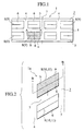
- FIGS. 1 and 2 show tread patterns 1 and 1a of a pneumatic radial tire according to an embodiment of the present invention.
- a wheel tread part of a tread is constituted of at least one circumferential groove formed in a circumferential direction and a plurality of traverse grooves formed at proper intervals in a width direction to intersect the circumferential groove, and divided into a plurality of blocks.
- a wheel tread part 2 of a tread is constituted of a longitudinal main groove (circumferential groove) 3 formed in a circumferential direction via a center of a width direction, a plurality of longitudinal subgrooves (circumferential grooves) 4 and 4 formed on both sides of the longitudinal main groove 3 in the circumferential direction, and a plurality of traverse grooves 5 formed at proper intervals in the width direction to intersect the longitudinal main and subgrooves 3 and 4, and divided into a plurality of blocks 6.
- Each of the plurality of blocks 6 is provided with at least one sipe 8 which intersects the circumferential direction, and formed so that rigidity of the block 6 in the width direction can be higher in an end a of a center side region (right hatched part in each of FIGS. 1 and 2) compared with that in an end b of a shoulder side region (left hatched part in each of FIGS. 1 and 2).
- the end a of the center side region and the end b of the shoulder side region are regions divided into the center and shoulder sides at a boundary of a center of the block 6 in the width direction for convenience.
- the longitudinal main groove 3 is formed along a tire equatorial plane 7, the longitudinal subgrooves 4 are formed in parallel with the longitudinal main groove 3, and the traverse groove 5 is formed orthogonally to the longitudinal main and subgrooves 3 and 4 (FIG. 1).
- the longitudinal main groove 3 is formed along the tire equatorial plane 7, the longitudinal subgrooves 4 are formed in parallel with the longitudinal main groove 3, and the traverse groove 5 is formed so as to obliquely cross the longitudinal main and subgrooves 3 and 4 (FIG. 2).
- tire drainage efficiency can be maintained at a high level in the rain by the longitudinal main and subgrooves 3 and 4.
- the rigidity of the block 6 is high on the center side (end a of the center side region), a reaction force is generated in accordance with a steering angle from the start of changing the same.
- the maintenance of the drainage efficiency at the high level enables to secure hydroplaning performance.
- accurate transmission of the reaction force in accordance with the steering angle to a driver is realized, whereby it becomes possible to improve a response of handling performance.
- the rigidity of the block 6 in the width direction can be easily controlled by a length and a cut depth of the sipe 8 disposed in the width direction, and/or the number of sipes to be set.
- the longitudinal subgrooves 4 are formed by at least one in each of both sides of the longitudinal main groove 3 and at least four rows of the plurality of blocks 6 are disposed along the longitudinal main and subgrooves 3 and 4.
- the sipe 8 is constituted of a one-end-open sipe 9 (FIGS. 1 and 3) in which the shoulder side is open and the center side is terminated in the block 6, or both-end-open sipes 10 and 11 (FIGS. 2, 4 and 5) formed so that a cut depth in the end a of the center side region becomes shallower compared with that in the end b of the shoulder side region.
- the one-end-open sipe 9 shown in FIGS. 1 and 3 has an opening 9a on the longitudinal subgroove 4 side (shoulder side), and formed to terminate in the block 6 while the cut depth thereof is maintained constant at a deepest.
- a part (projected part) 6a where no sipe 9 has been formed is left in the end a of the center side region.
- rigidity in the end a of the center side region can be set higher compared with that in the end b of the shoulder side region.
- the projected part 6a is formed so that its top width t1 can be 5 to 15% of a top width T1 of the block 6.
- T1 denotes a width of the top of the block 6 in the tread width direction
- t1 denotes a width of the top of the proj ected part 6a in the tread width direction.
- the both-end-open sipe 10 is formed by including a one-end opening 10a on the longitudinal subgroove 4 side and the other-end opening 10b on the longitudinal main groove 3 side which is provided by setting a cut dept to be shallower stepwise toward the longitudinal main groove 3.
- the both-end-open sipe 10 is formed into one step to include a deepest part 10c formed to be communicated with the one-end opening 10a and to have a depth equal to the cut depth of the sipe 9 and a shallowest part 10d formed to be communicated with the other-end opening 10b.
- a proj ected part 6b of which the shallowest part 10d is a top, is formed in the end a of the center side region.
- rigidity in the end a of the center side region can be set higher compared with that in the end b of the shoulder side region.
- the both-end-open sipe 10 is formed by including an end a of the center side region, in which a width t2 is 5 to 40% of a base part width T2 of the block 6, having a shallow cut depth.
- T2 denotes a width of the base part of the block 6 in the tread width direction
- t2 denotes a width of the base part of the projected part 6b in the tread width direction.
- the end a of the center side region with the shallow cut depth is formed to have the width t2 which is 5 to 40% of the block base part width T2.
- the both-end-open sipe 11 is formed by including a one-end opening 11a and the other-end opening 11b formed to sizes roughly equal to the one-end and other-end openings 10a and 10b of the aforementioned both-end opening sipe 10, respectively, in the same places. Moreover, a cut depth of the both-end-open sipe 11 is formed to be gradually shallower from the one-end opening 11a toward the other-end opening 11b.
- the rigidity of the block 6 can be controlled by changing a size of a cut area of the sipe 8 (9, 10, and 11).
- the cut area of the sipe 8 can be controlled by adjusting a depth or the like thereof so that the cut area of the sipe 8 in the tread width direction can be smaller in the end a of the center side region than that in the end b of the shoulder side region when seen from sections of the block 6 (sections cut along the lines A-A and B-B) along the cut surface of the sipe 8.
- the sipe 8 (9, 10, and 11) is formed to have the cut area smaller in the end a of the center side region than that in the end b of the shoulder side region.
- the block rigidity of the end a of the center side region can be higher compared with that of the end b of the shoulder side region by an amount corresponding to the smaller cut area of the sipe 8 on the end a side of the center side region.
- a sipe sectional area ratio for the cut area of the sipe8 in the tread width direction is represented by a ratio between a sipe sectional area S1 of the center side region and a sipe sectional area S2 of the shoulder side region.
- Table 1 shows a result of a real car test.
- Sipe Sipe sectional area ratio (S1:S2) Real car performance handling score Example 1 One-end-open sipe 9 (see FIG. 3) 1:1.89 7
- Example 2 Both-end-open sipe 10 (see FIG. 4) 1:1.45 6.5
- Example 3 Both-end-open sipe 11 (see FIG. 5) 1:1.52. 6.5
- Conventional example Both-end-open sipe 12 (see FIG. 6) 1:1.00 5
- Example 1 a one-end-open sipe 9 (see FIG. 3) was formed.
- a both-end-open sipe 10 (see FIG. 4) was formed by including an end a of a center side region, in which a width t2 was 5 to 40% of a block base part width T2, having a shallow cut depth.
- a both-end-open sipe 11 (see FIG. 5) was formed.
- FIG. 5 a conventional example, as shown in FIG.
- a both-end-open sipe 12 (a one-end opening 12a on a longitudinal subgroove 4 side and the other-end opening 12b on a longitudinal main groove 3 side are equal to each other in size) is formed to have a uniform cut depth equal to a deepest part of each of the Examples 1, 2, and 3.
- one sipe 8 is disposed for each block 6.
- the invention is not limited to this constitution. Two or more sipes can be disposed depending on a size of the block 6 and/or design of a tread pattern.
- Table 2 shows a result of a real car test conducted similarly to the above by using a tire which has a one-end-open sipe shown in FIG. 3.
- Example 4 One-end-open sipe (see FIG. 3) 1:1.4 6.5
- Example 5 One-end-open sipe (see FIG. 3) 1:2.0 7
- Comparative Example 1 One-end-open sipe (see FIG. 3) 1:1.3 5.5 Comparative Example 2
- Table 3 shows a result of a real car test conducted similarly to the above by using a tire which has a one-end-open sipe of FIG. 3.
- One-end-open sipe 9 see FIG. 3) 4 5.5
- Example 6 One-end-open sipe (see FIG. 3) 5 6.5
- Example 7 (Example 1) One-end-open sipe (see FIG. 3) 8 7
- Example 8 One-end-open sipe (see FIG. 3) 15 7.5 Comparative Example 4 One-end-open sipe (see FIG. 3) 16 8
- the drainage efficiency of the tire can be maintained at a high level in the rain by the circumferential groove, whereby it is possible to secure hydroplaning performance.
- the block rigidity of the end of the center side region is high, a reaction force is generated in accordance with a steering angle from the start of changing the same, and this reaction force is accurately transmitted to a driver. As a result, it is possible to improve a response of handling performance.
- one longitudinal main groove and at least a pair of longitudinal subgrooves it is possible to secure a groove volume necessary for maintaining the drainage efficiency of the tire at a high level in the rain. Thus, it is possible to secure higher hydroplaning performance.
- the block section along the sipe is formed such that the ratio between the sipe sectional area S2 of the shoulder side region and the sipe sectional area S1 of the center side region can be 1.4 ⁇ S2/S1 ⁇ 2.0.
- maximum effects can be obtained.
- a part where no sipe has been formed is left in the end of the center side region, whereby the block rigidity of the end of the center side region can be increased compared with that of the end of the shoulder side region.
- the block rigidity of the end of the center side region can be increased compared with that of the end of the shoulder side region.
- a width of the unopened part of the end of the center side region is formed to be in a range of 5 to 15% of the block width.
- the end of the center side region having the shallow cut depth is formed to have a width of 5 to 40% of the block base part width.
Landscapes
- Engineering & Computer Science (AREA)
- Mechanical Engineering (AREA)
- Tires In General (AREA)
Abstract
Description
| Sipe | Sipe sectional area ratio (S1:S2) | Real car performance handling score | |
| Example 1 | One-end- (see FIG. 3) | 1:1.89 | 7 |
| Example 2 | Both-end- (see FIG. 4) | 1:1.45 | 6.5 |
| Example 3 | Both-end- (see FIG. 5) | 1:1.52. | 6.5 |
| Conventional example | Both-end- (see FIG. 6) | 1:1.00 | 5 |
| Sipe | Sipe sectional area ratio (S1:S2) | Real car performance handling score | |
| Example 4 | One-end-open sipe (see FIG. 3) | 1:1.4 | 6.5 |
| Example 5 | One-end-open sipe (see FIG. 3) | 1:2.0 | 7 |
| Comparative Example 1 | One-end-open sipe (see FIG. 3) | 1:1.3 | 5.5 |
| Comparative Example 2 | One-end-open sipe (see FIG. 3) | 1:2.1 | 8 |
| Sipe | Ratio of block width of unopened part t1/T1 (%) | Real car performance handling score | |
| Comparative Example 3 | One-end- (see FIG. 3) | 4 | 5.5 |
| Example 6 | One-end-open sipe (see FIG. 3) | 5 | 6.5 |
| Example 7 (Example 1) | One-end-open sipe (see FIG. 3) | 8 | 7 |
| Example 8 | One-end-open sipe (see FIG. 3) | 15 | 7.5 |
| Comparative Example 4 | One-end-open sipe (see FIG. 3) | 16 | 8 |
Claims (9)
- A pneumatic radial tire in which a wheel tread part of a tread is divided into a plurality of blocks and is constituted of at least one circumferential groove formed in a circumferential direction and a plurality of traverse grooves formed at proper intervals in a width direction so as to intersect the circumferential groove,
characterized in that each of the plurality of blocks is provided with at least one sipe which intersects the circumferential direction, and is formed so that block rigidity can be higher in an end of a center side region compared with that in an end of a shoulder side region. - A pneumatic radial tire according to claim 1, characterized in that:the circumferential groove is constituted by including a longitudinal main groove formed in the circumferential direction via a center of the width direction, and a pair of longitudinal subgrooves disposed by at least one on each of both sides of the longitudinal main groove, andat least four rows of the plurality of blocks are disposed along the main and subgrooves.
- A pneumatic radial tire according to claim 1 or 2, characterized in that:a block section along the sipe is formed so that a cut depth of the end of the center side region can be shallower compared with that of the end of the shoulder side region.
- A pneumatic radial tire according to claim 1 or 2, characterized in that:a block section along the sipe is formed so that a cut area of the end of the center side region can be smaller compared with that of the end of the shoulder side region.
- A pneumatic radial tire according to one of claims 1, 2, and 4, characterized in that:on the block section along the sipe, a ratio between a sipe sectional area S2 of the shoulder side region and a sipe sectional area S1 of the center side region is as follows:
- A pneumatic radial tire according to one of claims 1 to 4, characterized in that:the sipe is constituted of a one-end-open sipe formed by opening the shoulder side of the block and terminating the center side in the block.
- A pneumatic radial tire according to claim 6, characterized in that:a width of an unopened part of the end of the center side region is 5 to 15% of a block width.
- A pneumatic radial tire according to one of claims 1 to 4, characterized in that:the sipe is constituted of a both-end-open sipe formed by opening both ends of the shoulder and center sides of the block.
- A pneumatic radial tire according to claim 8, characterized in that:the both-end-open sipe is formed by including an end of the center side region having a width of 5 to 40% of the block width and a shallow cut depth.
Applications Claiming Priority (3)
| Application Number | Priority Date | Filing Date | Title |
|---|---|---|---|
| JP2001394550 | 2001-12-26 | ||
| JP2001394550 | 2001-12-26 | ||
| PCT/JP2002/013621 WO2003055698A1 (en) | 2001-12-26 | 2002-12-26 | Pneumatic radial tire |
Publications (3)
| Publication Number | Publication Date |
|---|---|
| EP1468845A1 true EP1468845A1 (en) | 2004-10-20 |
| EP1468845A4 EP1468845A4 (en) | 2005-04-06 |
| EP1468845B1 EP1468845B1 (en) | 2010-08-18 |
Family
ID=19188881
Family Applications (1)
| Application Number | Title | Priority Date | Filing Date |
|---|---|---|---|
| EP02792006A Expired - Lifetime EP1468845B1 (en) | 2001-12-26 | 2002-12-26 | Pneumatic radial tire |
Country Status (6)
| Country | Link |
|---|---|
| US (1) | US7341083B2 (en) |
| EP (1) | EP1468845B1 (en) |
| JP (1) | JP4326338B2 (en) |
| CN (1) | CN1310777C (en) |
| DE (1) | DE60237399D1 (en) |
| WO (1) | WO2003055698A1 (en) |
Families Citing this family (12)
| Publication number | Priority date | Publication date | Assignee | Title |
|---|---|---|---|---|
| US7270162B2 (en) * | 2004-07-21 | 2007-09-18 | The Yokohama Rubber Co. Ltd. | Pneumatic tire with tread surface having blocks with sipes forming meandrous shape |
| JP2007015621A (en) * | 2005-07-08 | 2007-01-25 | Sumitomo Rubber Ind Ltd | Pneumatic tire and tire mold |
| FR2890600B1 (en) * | 2005-09-15 | 2010-02-26 | Michelin Soc Tech | IRREGULAR ANTI-WEAR DEVICE FOR PNEUMATIC BEARING BAND |
| JP4388569B2 (en) * | 2007-08-01 | 2009-12-24 | 住友ゴム工業株式会社 | Pneumatic tire |
| US20140230980A1 (en) * | 2011-09-29 | 2014-08-21 | Michelin Recherche Et Technique S.A. | Tire with tread having improved snow and dry traction |
| FR3014750B1 (en) * | 2013-12-17 | 2017-02-24 | Michelin & Cie | Tread comprising pavers and thin grooves on the paving stones |
| JP6720986B2 (en) * | 2016-01-29 | 2020-07-08 | 横浜ゴム株式会社 | Pneumatic tire and method for manufacturing pneumatic tire |
| JP6627554B2 (en) * | 2016-02-15 | 2020-01-08 | 住友ゴム工業株式会社 | Pneumatic tire |
| CN109153292B (en) * | 2016-04-28 | 2020-11-10 | 株式会社普利司通 | Tyre for vehicle wheels |
| JP6825434B2 (en) * | 2017-03-16 | 2021-02-03 | 住友ゴム工業株式会社 | tire |
| JP7070180B2 (en) * | 2018-07-12 | 2022-05-18 | 住友ゴム工業株式会社 | tire |
| DE112020000319B9 (en) | 2019-02-22 | 2023-03-23 | The Yokohama Rubber Co., Ltd. | tire |
Family Cites Families (14)
| Publication number | Priority date | Publication date | Assignee | Title |
|---|---|---|---|---|
| JPH0741777B2 (en) * | 1986-04-14 | 1995-05-10 | オ−ツタイヤ株式会社 | Studless pneumatic tire |
| JPS63137003A (en) | 1986-11-29 | 1988-06-09 | Yokohama Rubber Co Ltd:The | Tire for snowy or icy road |
| JPH01233104A (en) * | 1988-03-14 | 1989-09-18 | Sumitomo Rubber Ind Ltd | Radial tire |
| JP2890310B2 (en) * | 1989-01-30 | 1999-05-10 | 横浜ゴム株式会社 | Pneumatic radial tire |
| JPH0392403A (en) * | 1989-09-04 | 1991-04-17 | Bridgestone Corp | Pneumatic tire having block pattern with sipe |
| IT1239977B (en) * | 1990-05-14 | 1993-11-27 | Pirelli Coordinamento Pneumatici Spa | TIRES FOR MOTOR VEHICLES |
| FI944892L (en) * | 1993-11-18 | 1995-08-18 | Bridgestone Corp | Pneumatic tire |
| JP3391538B2 (en) * | 1994-02-02 | 2003-03-31 | 住友ゴム工業株式会社 | studless tire |
| CN2203939Y (en) * | 1994-09-12 | 1995-07-26 | 李石生 | Tyre with tread pattern of ribs |
| JPH09109613A (en) | 1995-10-17 | 1997-04-28 | Yokohama Rubber Co Ltd:The | Pneumatic radial tire |
| JP3631559B2 (en) * | 1996-06-13 | 2005-03-23 | 株式会社ブリヂストン | Pneumatic tire |
| JP4149055B2 (en) * | 1998-12-09 | 2008-09-10 | 株式会社ブリヂストン | Pneumatic tire with central rib and multiple rows of blocks |
| JP4201901B2 (en) * | 1998-12-24 | 2008-12-24 | 株式会社ブリヂストン | Pneumatic radial tire |
| JP4388159B2 (en) | 1999-03-09 | 2009-12-24 | 住友ゴム工業株式会社 | tire |
-
2002
- 2002-12-26 DE DE60237399T patent/DE60237399D1/en not_active Expired - Lifetime
- 2002-12-26 EP EP02792006A patent/EP1468845B1/en not_active Expired - Lifetime
- 2002-12-26 CN CNB028271718A patent/CN1310777C/en not_active Expired - Fee Related
- 2002-12-26 JP JP2003556253A patent/JP4326338B2/en not_active Expired - Fee Related
- 2002-12-26 WO PCT/JP2002/013621 patent/WO2003055698A1/en not_active Ceased
- 2002-12-26 US US10/500,244 patent/US7341083B2/en not_active Expired - Fee Related
Also Published As
| Publication number | Publication date |
|---|---|
| EP1468845B1 (en) | 2010-08-18 |
| EP1468845A4 (en) | 2005-04-06 |
| DE60237399D1 (en) | 2010-09-30 |
| JP4326338B2 (en) | 2009-09-02 |
| US7341083B2 (en) | 2008-03-11 |
| JPWO2003055698A1 (en) | 2005-04-28 |
| US20050016652A1 (en) | 2005-01-27 |
| CN1310777C (en) | 2007-04-18 |
| CN1615230A (en) | 2005-05-11 |
| WO2003055698A1 (en) | 2003-07-10 |
Similar Documents
| Publication | Publication Date | Title |
|---|---|---|
| CN109927488B (en) | Tire with a tire body | |
| JP3061276B2 (en) | Pneumatic tire | |
| EP1780052B1 (en) | Pneumatic tire and method of producing the same | |
| EP1033267B1 (en) | Pneumatic tire | |
| US7341083B2 (en) | Pneumatic radial tire with tread having blocks provided with sipes | |
| CN109591520B (en) | Tyre for vehicle wheels | |
| US20070240801A1 (en) | Pneumatic Tire | |
| US20180001710A1 (en) | Pneumatic tire | |
| EP1566291A1 (en) | Pneumatic tire | |
| EP1270271B1 (en) | Studless tire | |
| AU2009318659B2 (en) | Pneumatic tire | |
| JP3113388B2 (en) | Pneumatic tire | |
| JP2002264614A (en) | tire | |
| US8002005B2 (en) | Pneumatic tire with tread including three dimensional sipes having at least two tie bars | |
| JPH0939515A (en) | Pneumatic tires for passenger cars | |
| JP2008105615A (en) | Pneumatic tire | |
| JP2749879B2 (en) | Pneumatic tire with asymmetric tread | |
| EP4151431B1 (en) | Tire | |
| US12600172B2 (en) | Tire | |
| US20120037288A1 (en) | Pneumatic tire | |
| EP4497609B1 (en) | Pneumatic tire | |
| JPH08183312A (en) | Pneumatic tires for ice and snow roads | |
| JPH06297917A (en) | Pneumatic radial tire | |
| KR100836440B1 (en) | Pattern Structure of Pneumatic Radial Tires for Heavy Load | |
| US20240343069A1 (en) | Tire |
Legal Events
| Date | Code | Title | Description |
|---|---|---|---|
| PUAI | Public reference made under article 153(3) epc to a published international application that has entered the european phase |
Free format text: ORIGINAL CODE: 0009012 |
|
| 17P | Request for examination filed |
Effective date: 20040702 |
|
| AK | Designated contracting states |
Kind code of ref document: A1 Designated state(s): AT BE BG CH CY CZ DE DK EE ES FI FR GB GR IE IT LI LU MC NL PT SE SI SK TR |
|
| A4 | Supplementary search report drawn up and despatched |
Effective date: 20050217 |
|
| 17Q | First examination report despatched |
Effective date: 20070711 |
|
| GRAP | Despatch of communication of intention to grant a patent |
Free format text: ORIGINAL CODE: EPIDOSNIGR1 |
|
| GRAS | Grant fee paid |
Free format text: ORIGINAL CODE: EPIDOSNIGR3 |
|
| GRAA | (expected) grant |
Free format text: ORIGINAL CODE: 0009210 |
|
| AK | Designated contracting states |
Kind code of ref document: B1 Designated state(s): DE ES FR GB IT |
|
| REG | Reference to a national code |
Ref country code: GB Ref legal event code: FG4D |
|
| REF | Corresponds to: |
Ref document number: 60237399 Country of ref document: DE Date of ref document: 20100930 Kind code of ref document: P |
|
| PLBE | No opposition filed within time limit |
Free format text: ORIGINAL CODE: 0009261 |
|
| STAA | Information on the status of an ep patent application or granted ep patent |
Free format text: STATUS: NO OPPOSITION FILED WITHIN TIME LIMIT |
|
| PG25 | Lapsed in a contracting state [announced via postgrant information from national office to epo] |
Ref country code: ES Free format text: LAPSE BECAUSE OF FAILURE TO SUBMIT A TRANSLATION OF THE DESCRIPTION OR TO PAY THE FEE WITHIN THE PRESCRIBED TIME-LIMIT Effective date: 20101129 |
|
| 26N | No opposition filed |
Effective date: 20110519 |
|
| GBPC | Gb: european patent ceased through non-payment of renewal fee |
Effective date: 20101226 |
|
| REG | Reference to a national code |
Ref country code: DE Ref legal event code: R097 Ref document number: 60237399 Country of ref document: DE Effective date: 20110519 |
|
| PG25 | Lapsed in a contracting state [announced via postgrant information from national office to epo] |
Ref country code: GB Free format text: LAPSE BECAUSE OF NON-PAYMENT OF DUE FEES Effective date: 20101226 |
|
| REG | Reference to a national code |
Ref country code: DE Ref legal event code: R082 Ref document number: 60237399 Country of ref document: DE Representative=s name: BARDEHLE PAGENBERG PARTNERSCHAFT MBB PATENTANW, DE |
|
| REG | Reference to a national code |
Ref country code: FR Ref legal event code: CA Effective date: 20140812 |
|
| REG | Reference to a national code |
Ref country code: DE Ref legal event code: R082 Ref document number: 60237399 Country of ref document: DE Representative=s name: BARDEHLE PAGENBERG PARTNERSCHAFT MBB PATENTANW, DE Effective date: 20140828 Ref country code: DE Ref legal event code: R081 Ref document number: 60237399 Country of ref document: DE Owner name: BRIDGESTONE CORPORATION, JP Free format text: FORMER OWNER: BRIDGESTONE CORP., TOKIO/TOKYO, JP Effective date: 20140828 |
|
| REG | Reference to a national code |
Ref country code: FR Ref legal event code: PLFP Year of fee payment: 14 |
|
| REG | Reference to a national code |
Ref country code: FR Ref legal event code: PLFP Year of fee payment: 15 |
|
| PGFP | Annual fee paid to national office [announced via postgrant information from national office to epo] |
Ref country code: IT Payment date: 20161223 Year of fee payment: 15 |
|
| REG | Reference to a national code |
Ref country code: FR Ref legal event code: PLFP Year of fee payment: 16 |
|
| PGFP | Annual fee paid to national office [announced via postgrant information from national office to epo] |
Ref country code: FR Payment date: 20171221 Year of fee payment: 16 Ref country code: DE Payment date: 20171211 Year of fee payment: 16 |
|
| PG25 | Lapsed in a contracting state [announced via postgrant information from national office to epo] |
Ref country code: IT Free format text: LAPSE BECAUSE OF NON-PAYMENT OF DUE FEES Effective date: 20171226 |
|
| REG | Reference to a national code |
Ref country code: DE Ref legal event code: R119 Ref document number: 60237399 Country of ref document: DE |
|
| PG25 | Lapsed in a contracting state [announced via postgrant information from national office to epo] |
Ref country code: DE Free format text: LAPSE BECAUSE OF NON-PAYMENT OF DUE FEES Effective date: 20190702 Ref country code: FR Free format text: LAPSE BECAUSE OF NON-PAYMENT OF DUE FEES Effective date: 20181231 |