EP1468835A1 - Printer - Google Patents
Printer Download PDFInfo
- Publication number
- EP1468835A1 EP1468835A1 EP04008846A EP04008846A EP1468835A1 EP 1468835 A1 EP1468835 A1 EP 1468835A1 EP 04008846 A EP04008846 A EP 04008846A EP 04008846 A EP04008846 A EP 04008846A EP 1468835 A1 EP1468835 A1 EP 1468835A1
- Authority
- EP
- European Patent Office
- Prior art keywords
- card
- top cover
- printer
- cover unit
- unit
- Prior art date
- Legal status (The legal status is an assumption and is not a legal conclusion. Google has not performed a legal analysis and makes no representation as to the accuracy of the status listed.)
- Granted
Links
Images


Classifications
-
- G—PHYSICS
- G07—CHECKING-DEVICES
- G07F—COIN-FREED OR LIKE APPARATUS
- G07F7/00—Mechanisms actuated by objects other than coins to free or to actuate vending, hiring, coin or paper currency dispensing or refunding apparatus
- G07F7/02—Mechanisms actuated by objects other than coins to free or to actuate vending, hiring, coin or paper currency dispensing or refunding apparatus by keys or other credit registering devices
-
- B—PERFORMING OPERATIONS; TRANSPORTING
- B41—PRINTING; LINING MACHINES; TYPEWRITERS; STAMPS
- B41J—TYPEWRITERS; SELECTIVE PRINTING MECHANISMS, i.e. MECHANISMS PRINTING OTHERWISE THAN FROM A FORME; CORRECTION OF TYPOGRAPHICAL ERRORS
- B41J15/00—Devices or arrangements of selective printing mechanisms, e.g. ink-jet printers or thermal printers, specially adapted for supporting or handling copy material in continuous form, e.g. webs
- B41J15/04—Supporting, feeding, or guiding devices; Mountings for web rolls or spindles
- B41J15/042—Supporting, feeding, or guiding devices; Mountings for web rolls or spindles for loading rolled-up continuous copy material into printers, e.g. for replacing a used-up paper roll; Point-of-sale printers with openable casings allowing access to the rolled-up continuous copy material
-
- G—PHYSICS
- G06—COMPUTING; CALCULATING OR COUNTING
- G06Q—INFORMATION AND COMMUNICATION TECHNOLOGY [ICT] SPECIALLY ADAPTED FOR ADMINISTRATIVE, COMMERCIAL, FINANCIAL, MANAGERIAL OR SUPERVISORY PURPOSES; SYSTEMS OR METHODS SPECIALLY ADAPTED FOR ADMINISTRATIVE, COMMERCIAL, FINANCIAL, MANAGERIAL OR SUPERVISORY PURPOSES, NOT OTHERWISE PROVIDED FOR
- G06Q20/00—Payment architectures, schemes or protocols
- G06Q20/30—Payment architectures, schemes or protocols characterised by the use of specific devices or networks
- G06Q20/34—Payment architectures, schemes or protocols characterised by the use of specific devices or networks using cards, e.g. integrated circuit [IC] cards or magnetic cards
- G06Q20/343—Cards including a counter
-
- G—PHYSICS
- G07—CHECKING-DEVICES
- G07G—REGISTERING THE RECEIPT OF CASH, VALUABLES, OR TOKENS
- G07G1/00—Cash registers
- G07G1/0018—Constructional details, e.g. of drawer, printing means, input means
-
- G—PHYSICS
- G07—CHECKING-DEVICES
- G07G—REGISTERING THE RECEIPT OF CASH, VALUABLES, OR TOKENS
- G07G5/00—Receipt-giving machines
Definitions
- the present invention relates to a medium transportation mechanism and a printer capable of printing on both continuous paper and slips, and reading image data recorded on a card or other recording medium.
- Endless or roll paper printers that print on roll paper for issuing sales receipts, entrance tickets, and the like, and slip printers for printing on personal and business checks and other types of slips, are widely used. These printers include hybrid printers having both a roll paper printing function and slip printing function so that a single printer can print on both roll paper and slips.
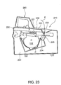
- the hybrid printer 210 shown in Fig. 23 has a roll paper P loading opening 221 on top of the case 220, and a compartment 222 for a roll of paper P inside the case 220.
- the roll of paper P is held freely rotatably inside the compartment 222 with one end of the roll paper P delivered to the front inside the case 220 so that it passes through a transportation path 223 formed inside the case 220 when the cover 230 is closed.
- a thermal print head 224 is disposed along this transportation path 223, and prints on the roll paper P.
- the cover 230 opens and closes the loading opening 221, and has a slip insertion face 231 for inserting slips at the top front side of the cover 230.
- a slip guide 232 is formed along the insertion direction of the slip S along one edge of this slip insertion face 231.
- a roll paper P exit 225 is formed by the gap between the case 220 and an edge of the cover 230 when the cover 230 is closed, at a position below the slip insertion face 231.
- a slip printing unit 260 is also disposed at the top back part of the cover 230. See, for example, JP 2001-341369 A (page 5, Fig. 2).
- Scanners for capturing image data recorded/printed on such media as driver licenses and credit cards with a photograph of the credit card holder are increasingly installed in stores in conjunction with hybrid printers such as the one described above. This obviously requires sufficient space to install both the hybrid printer and the scanner, that is, two separate devices, and thus often requires some modification to create the needed space. More specifically, the scanner and the hybrid printer are typically installed at a checkout counter where space is limited, and it can be difficult to provide space sufficient to install both of them.
- the scanner and the hybrid printer are two discrete devices, the scanner and the hybrid printer operate independently. Two devices must therefore be operated, and this reduces overall operating and job efficiency.
- the present invention is directed to solving these problems, and an object of the invention is to provide a printer offering both a printer function and a scanner function, an efficient operation, and an efficient installation in confined spaces.
- a further object of the invention is to provide a media transportation mechanism used in a scanner mechanism.
- to read image data is used in this text in a broad sense covering both the scanning of an image such as a photograph to convert the image to image data for further processing, and the reading of image data stored in any of various ways, including one or two-dimensional bar codes, on a card as a data carrier.
- image or image data and the way of scanning or reading it is not critical for the present invention in its broadest aspect.
- a first embodiment of a printer with an image scanning sensor according to the present invention is described below.
- Fig. 1 is a perspective view of a printer 10 with an image scanning sensor according to a first embodiment of the invention.
- Fig. 2 is a schematic view showing the major parts of the slip transportation path.
- Fig. 3 is a perspective view showing the top cover unit of the printer 10.
- Fig. 4 is a partial sectional view of the printer 10.
- Fig. 5 and Fig. 6 are a perspective view and a sectional view, respectively, showing the printer when the top cover unit is open.
- Fig. 7 and Fig. 8 are a perspective view and a sectional view, respectively, showing the printer when the top cover unit is open and the internal cover thereinside is also open.
- Fig. 9 is a sectional view showing the top of the card transportation path when the internal cover is open.
- Fig. 1 is a perspective view of a printer 10 with an image scanning sensor according to a first embodiment of the invention.
- Fig. 2 is a schematic view showing the major parts of the slip transportation path.
- Fig. 3
- Fig. 10 is a perspective view showing he shutter.
- Fig. 11 and Fig. 12 are sectional views showing the top cover unit in order to describe the opening/closing operation of the shutter.
- Fig. 13 is a perspective view showing the card insertion opening when the shutter is closed.
- Printer 10 can print both on roll paper P (see Fig. 4) and on slips S (see Fig. 2), and can read image data recorded on a card C (see Fig. 4).
- This printer 10 has an integrally configured back case unit 11, front cover unit 12, and top cover unit 13.
- the back case unit 11 houses a roll of paper P as a continuous recording medium inside a case 11 a, and a printer mechanism for printing on the roll of paper P.
- the front cover unit 12 is disposed in front of the back case unit 11, and forms a slip transportation path 21 through which slips S are conveyed between the front cover unit 12 and back case unit 11.
- the top cover unit 13 is assembled in order to cover the top of the back case unit 11, and houses an image scanning sensor mechanism for reading image data recorded on cards and other media.
- the front cover unit 12 is composed of a front cover 12a separated from the back case unit 11 by the slip transportation path 21, and a front side unit 12b supporting the front cover 12a in a cantilevered manner. As shown in Fig. 1 and Fig. 2, a slip S can be inserted into the slip transportation path 21 from the slip insertion opening 21a, which opens into the gap between the case 11 a of back case unit 11 and front cover 12a of front cover unit 12 at the front of the printer 10.
- a slip S inserted into the slip transportation path 21 is conveyed to a back printing unit 23 disposed at the slip transportation path 21 by a first slip transportation roller 22a and a first slip pressure roller 22b, which are disposed opposite to each other with the slip transportation path 21 in between.
- the back printing unit 23 is composed of a serial impact dot matrix printing unit 23a disposed on the reverse or back side of the slip S, and a platen 23b disposed opposite the dot matrix printing unit 23a with the slip transportation path 21 therebetween. This dot matrix printing unit 23a prints on the reverse (back) side of the slip S.
- slips S As the slips S is conveyed downstream from the back printing unit 23, it is carried by a second slip transportation roller 24a and second slip pressure roller 24b, which are disposed opposite to each other with the slip transportation path 21 in between, to a front printing unit 25 also disposed at the slip transportation path 21.
- This front printing unit 25 is composed of a serial impact dot matrix printing unit 25a disposed at the front side of the slip S and a platen 25b, which are disposed opposite to each other with the slip transportation path 21 in between. This dot matrix printing unit 25a can thus print the front of the slip S.
- the slip S is then conveyed further downstream from the front printing unit 25, it passes the slip image scanning sensor 26.
- the slip image scanning sensor 26 is a contact image sensor (CIS) type image scanner, and is disposed to scan the front side of the slip S.
- a pressure roller 27 is disposed opposite the slip image scanning sensor 26 with the slip transportation path 21 therebetween. This pressure roller 27 presses the slip S to the scanning surface 26a of the slip image scanning sensor 26 by means of pressure member 27a with a specific pressure corresponding to the thickness of the slip.
- the slip image scanning sensor 26 is configured to read image data recorded on the front of the slip image scanning sensor 26 with the slip S pressed onto the scanning surface 26a by the pressure roller 27. The slip S is then discharged from the slip exit 21 b after it passed between the slip image scanning sensor 26 and pressure roller 27.
- a trailing edge sensor 28a disposed at the slip insertion opening 21a, and a leading edge sensor 28b disposed downstream of the second slip pressure roller 22b, are used to detect the presence of a slip S in the slip transportation path 21, and to control indexing it to the front printing unit 25 and back printing unit 23 when the slip is being printed.
- An ejection detector 29 is disposed between the front printing unit 25 and the slip image scanning sensor 26 for detecting if the slip S has been discharged from the slip transportation path 21.
- the roll paper transportation path 35 is formed between the back case unit 11 and the top cover unit 13.
- the roll of paper P is housed in a roll paper compartment 30, which is formed by a roll paper support wall 31 inside the back case unit 11.
- the paper P drawn off the roll is conveyed along the roll paper transportation path 35, and is discharged from the roll paper exit 35a opened between the case 11 a and top cover 13a.
- the roll paper compartment 30 is a drop-in type roll paper compartment enabling the roll of paper P to be simply dropped into the roll paper compartment 30. Paper is supplied from the roll as it rotates guided by the roll paper support wall 31. The end of the roll paper P inside the roll paper compartment 30 is pulled out from the roll paper compartment 30 and passed between the platen roller 32 and thermal print head 33.
- the axle 32a of the platen roller 32 is axially supported by the frame 51 of the top cover unit 13 so as to be freely rotatable as shown in Fig. 5.
- a gear 32b on the end of the axle 32a is rotationally driven by a motor not shown, thereby rotating the platen roller 32 and conveying the roll paper P.
- the thermal print head 33 is configured for printing text on the roll paper P conveyed by the platen roller 32.
- the printed roll paper P then passes through the roll paper transportation path 35 and is discharged from the roll paper exit 35a.
- an automatic paper cutter 34 is disposed above the platen roller 32 and the thermal print head 33.
- This automatic paper cutter 34 has a stationary knife 34a disposed on one side of the roll paper transportation path 35, and a movable knife 34b disposed on the other side of the roll paper transportation path 35 opposite the stationary knife 34a.
- the stationary knife 34a is supported by the frame 51 of the top cover unit 13 near the platen roller 32 as shown in Fig. 5.
- the movable knife 34b is configured movably to the roll paper transportation path in the direction of arrow A in Fig. 4 so that it can cut the roll paper P between the movable knife 34b and stationary knife 34a.
- a fixed knife 36 is disposed with its lengthwise direction crosswise to the roll paper exit 35a near the roll paper exit 35a as shown in Fig. 3. This fixed knife 36 is used to manually cut the roll paper P. While this embodiment of the invention has both an automatic paper cutter 34 and a fixed knife 36 for manually cutting the roll paper, the invention could be configured using only either one of the two.
- the main frame 51 Disposed below the top cover unit 13 is the main frame 51 as shown in Fig. 5 and Fig. 6.
- This frame 51 is arranged to swing on a hinge 52 relative to a stationary part 53 assembled to the back case unit 11, thereby enabling the top cover unit 13 to open and close the roll paper compartment 30.
- the top cover unit 13 is pivoted on the hinge 52 into an open position so that roll paper P can be inserted to the roll paper compartment 30.
- a card image scanning unit 40 disposed between the top cover 13a and the roll paper compartment 30 is described next. As shown in Fig. 4, the card image scanning unit 40 is disposed so as to enable thick media such as a card C to be inserted through a card insertion slot 41a to the card transportation path 41 so that image data can be captured from the card C.
- a first transportation roller 43a, a card image scanning sensor 44, and a second transportation roller 46a are disposed in the card image scanning unit 40 along the card transportation path 41 on the top side thereof (as viewed in Fig. 4), that is, on the top cover 13a side.
- a first pressure roller 43b, a pressure roller 45, and a second pressure roller 46b are disposed opposite the first transportation roller 43a, the card image scanning sensor 44, and the second transportation roller 46a, respectively.
- the first transportation roller 43a and first pressure roller 43b are located between the card insertion slot 41a and the card image scanning sensor 44 for conveying a card C inserted into the card transportation path 41 bidirectionally through the card transportation path 41.
- a card C conveyed by the first transportation roller 43a and the first pressure roller 43b is carried between the card image scanning sensor 44 and the pressure roller 45.
- the card image scanning sensor 44 is a CIS scanner for reading text and images printed or otherwise provided on the front of the card.
- the card image scanning sensor 44 scans the text and/or images on the surface of the card C to obtain corresponding image data of. While being scanned the card C is pressed against the scanning surface 44a of the card image scanning sensor 44 by pressure roller 45 with a pressure appropriate to the card thickness.
- the second transportation roller 46a and the second pressure roller 46b are located downstream from the card image scanning sensor 44, and convey a card C inserted to the card transportation path 41 bidirectionally through the card transportation path 41.
- An overhang opening 41b is formed on the side of the second transportation roller 46a and the second pressure roller 46b remote from the opposite card image scanning sensor 44 where the card transportation path 41 crosses the outline of the top cover 13a.
- the card C supplied from the card insertion slot 41a is conveyed by the first transportation roller 43a and the first pressure roller 43b, and the second transportation roller 46a and the second pressure roller 46b, from the card insertion slot 41a side toward the overhang opening 41b until the card C has passed completely beyond the card image scanning sensor 44.
- the card C is then conveyed back toward the card insertion slot 41a side by driving the first transportation roller 43a and the second transportation roller 46a in reverse.
- the text or image on the card C surface is scanned/read by the card image scanning sensor 44 as the card C passes over the scanning surface 44a of the card image scanning sensor 44. After reading the card C ends, the card C is discharged from the printer 10 from the card insertion slot 41a.
- the second transportation roller 46a is set so that the card C can project from the outer edge of the overhang opening 41b by a length shorter than the distance L between the back side of the back case unit 11 and the position Po where the top cover unit 13 is farthest from the back side of the printer, that is, from the back side of the back case unit 11, when the top cover unit 13 is open as shown in Fig. 6.
- First pressure roller 43b, pressure roller 45, and second pressure roller 46b located on the roll paper compartment 30 side are rotatably supported on an internal cover 42 disposed between the card transportation path 41 and the roll paper compartment 30.
- a card transportation surface 42a defining part of the card transportation path 41 is formed on the top side of the internal cover 42.
- the first pressure roller 43b, the pressure roller 45, and the second pressure roller 46b are disposed protruding from the card transportation surface 42a so that they respectively contact the first transportation roller 43a, the card image scanning sensor 44, and the second transportation roller 46a.
- guide walls 54 project substantially perpendicularly to the top cover unit 13 along the direction of card transportation, and the internal cover 42 is rotatably assembled to the guide walls 54 by means of a hinge 55. More specifically, the hinge 55 is disposed on the back side of the internal cover 42, and the front of the internal cover 42 faces upward when the top cover unit 13 is opened. The internal cover 42 can then be opened so that the front of the internal cover 42 faces the front of the printer 10, thereby enabling easy access to and maintenance of the card transportation path 41 parts from the front of the printer 10.
- the guide walls 54 are configured as guides correcting the insertion direction of the card C inserted into the card transportation path 41. For example, if the card C is inserted at a slight angle to the card transportation direction (which is perpendicular to the card insertion slot 41a and parallel to the card transportation surface 42a), the direction of card C travel will turn when the card C contacts one of the guide walls 54 as it is conveyed by the first transportation roller 43a and the second transportation roller 46a. As a result, the guide walls 54 correct the direction of card transportation when the card C is inserted at a slight angle to the card transportation direction.
- This correction of the card transportation direction by the first transportation roller 43a and the first pressure roller 43b, and the second transportation roller 46a and the second pressure roller 46b, occurs while the card C is being carried from the card insertion slot 41a to the overhang opening 41b, and is completed by the time the card C has passed completely the card image scanning sensor 44. Therefore, after the card C has passed completely beyond the card image scanning sensor 44, the card C is conveyed in the card transportation direction over the scanning surface 44a of the card image scanning sensor 44. As a result, the card image scanning sensor 44 is assured of always capturing images on card C at the same angle.
- a card insertion detection sensor 48 is positioned near the card insertion slot 41a in the card transportation path 41.
- This card insertion detection sensor 48 is for detecting a card or other medium inserted into the card insertion slot 41a.
- the first transportation roller 43a and the second transportation roller 46a are configured to start driving after this card insertion detection sensor 48 detects that a card was inserted. As a result, the start of card transportation through the card transportation path 41 is triggered by inserting a card.
- This card insertion detection sensor 48 can also be configured to detect the card length at card insertion and the card length when the card is discharged.
- the card length at insertion is relative to the time from when the card C is detected by the card insertion detection sensor 48 and fed into the card transportation path 41 until the card C is no longer detected by the sensor 48.
- the card length when the card C is discharged is relative to the time from when the card C is detected after information is captured from the card C by the card image scanning sensor 44 until the card C is discharged from the card insertion slot 41a and the card C is no longer detected by the sensor 48.
- the printer 10 can thus determine that the card C was not conveyed at a constant speed due to some unknown external factor, for example, when the card was inserted or when the card was discharged after scanning, and to thus determine that capturing image data from the card C failed.
- the card length could be detected using the card image scanning sensor 44 instead of using the card insertion detection sensor 48.
- the card image scanning sensor 44 detects the card length at insertion based on the time from when the card C is detected to the time when the card C is conveyed completely downstream from the card image scanning sensor 44 and is no longer detected, and detects the card length at discharge based on the time from when the card image scanning sensor 44 starts reading information from the card C until the time the card C is conveyed toward the card insertion slot 41a and is discharged therefrom.
- the card image scanning sensor 44 thus performs the same detection as the card insertion detection sensor 48.
- a shutter 47 and a lever 61 are also provided as a medium insertion prevention mechanism to prevent insertion of a card C into the card insertion slot 41a when the internal cover 42 is open.
- the shutter 47 is an integral molding having a rotary shaft 47a, an arc-shaped base 47b fixed near the center of the arc near one end of the rotary shaft 47a, an arc-shaped insertion prevention part 47c fixed near the center of the arc near the other end of the rotary shaft 47a, a reinforcing member 47d disposed between the base 47b and the insertion prevention part 47c, and an operating lever 47e provided integrally to the base 47b.
- the shutter 47 is arranged between the card insertion slot 41a and the first transportation roller 43a with the rotary shaft 47a axially supported freely rotatably by a fixed part 50 provided on the top cover 13a side of the card transportation path 41.
- the lever 61 is disposed on the side of the internal cover 42 at a position where the lever 61 contacts the operating lever 47e when the internal cover 42 is closed.
- the lever 61 thus contacts the operating lever 47e of the shutter 47, thereby pushing the shutter 47 away from the card transportation path 41.
- the shutter 47 is urged from this position in the direction rotating towards the card transportation path 41 by a spring member 49.
- a printer has a back case unit 11 including a roll paper compartment 30 for holding a roll of paper P; a front cover unit 12 forming a slip transportation path 21 for conveying a slip S between the back case unit 11 and the front cover unit 12; a top cover unit 13 arranged to open and close so that the roll paper compartment 30 of the back case unit 11 is covered when the top cover unit 13 is closed, and forming a roll paper transportation path 35 for conveying the roll paper P between the back case unit 11 and the top cover unit 13; a front printing unit 25 and a back printing unit 23 disposed along the slip transportation path 21 as a slip printing unit for printing on slips S; a thermal print head 33 disposed along the roll paper transportation path 35 for printing on the roll paper P; and a card image scanning sensor 44 disposed at the top cover unit 13 as an image scanner for capturing an image on a card C.
- printer according to this embodiment it is therefore possible, using printer according to this embodiment to print on slips S, print on roll paper P, and capture an image from cards C using a single printer 10 with an image scanning sensor.
- a printer according to the present invention enables printing on slips S, printing on roll paper P, and capturing image data from cards C using only the space needed to install a single device.
- a printer according to this embodiment also has an internal cover 42 located between the top cover unit 13 and the back case unit 11 and arranged to open and close to the top cover unit 13.
- a card transportation path 41 is formed between the internal cover 42 and the top cover unit 13 for conveying a card C, and a card image scanning sensor 44 is disposed along this card transportation path 41.
- a printer according to this embodiment affords easily cleaning components, parts replacement, and maintenance of parts on and around the card transportation path 41 by opening the top cover unit 13 and then opening the internal cover 42.
- a printer according to this embodiment also has a card insertion slot 41a provided at the top cover unit 13 for inserting a card C into the card transportation path 41, and has a medium insertion prevention mechanism prohibiting a card C from being inserted into the card insertion slot 41a when the internal cover 42 is open.
- a printer according to this embodiment thus comprised prohibits insertion of a card C through the card insertion slot 41a when the internal cover 42 is open. Inserting a card when the card transportation path 41 is not formed, that is, when scanning is not possible, might cause accidental damage to the printer resulting from forcibly inserting a card.
- the medium insertion prevention mechanism of a printer has a shutter 47 rotatably disposed at the top cover unit 13 for blocking the card transportation path 41 when the internal cover 42 is open, and a lever 61 disposed at the internal cover 42 for holding the shutter 47 in a specific retracted position allowing insertion of a card C into the card insertion slot 41a when the internal cover 42 is closed.
- a medium insertion prevention mechanism can thus be easily provided in a printer according to this embodiment by adding the simple configuration of a shutter 47 and a lever 61 for holding the shutter 47 in a particular position according to the open or closed position of the internal cover 42.
- the top cover unit 13 of a printer according to this embodiment also has guide walls 54 for guiding a card C in the card transportation path 41.
- the guide walls 54 in this printer correct the insertion direction of the card C to align with the card transportation direction, thereby ensuring that the card image scanning sensor 44 always reads image data from the card C at the same angle.
- a printer according to this embodiment can be configured to measure the card length using a card insertion detection sensor 48 rather than using the card image scanning sensor 44.
- a printer according to this embodiment also has an overhang opening 41b disposed at the top cover unit 13 so that a card C inserted into the card transportation path 41 can temporarily project outside of the top cover unit 13.
- this configuration of the invention can increase the effective length of the card transportation path 41 by letting the card C project to the outside.
- a compact card image scanning unit 40 can therefore be achieved.
- the amount of projection of the card C from the overhang opening 41b in a printer according to this embodiment is smaller than the distance L between the position Po where the top cover unit 13 is farthest from the back side of the printer 10 and the back side of the case 11 when the top cover unit 13 is fully open.
- the printer 10 if the printer 10 is installed with its back facing a wall and is located to assure this distance L between the case and the wall when the top cover unit 13 is open, the card C will not hit the wall at the back of the printer when the card C projects from the overhang opening 41 if the overhang of the card C is smaller than this distance L. This enables to use the printer 10 without being concerned about the card C hitting the wall when the card C projects from the overhang opening 41b.
- This embodiment provides both a front printing unit 25 and a back printing unit 23 for printing on slips S so that both the front and back sides can be printed with the slip S passing through the slip transportation path 21 only once.
- This embodiment is configured with a scanner at the slip transportation path 21 for capturing an image/image data from the slip S. If the inserted slip S is a check, for example, this configuration enables the slip image scanning sensor 26 to capture an image on the check, and the card image scanning unit 40 to capture an image on the driver license or other identification presented by the person writing the check. By thus reading the check and reading a driver license or other identification containing information useful for verifying the person presenting the check using the printer 10 according to this embodiment, it is easy to later verify who presented the check.
- the captured image data could also be sent to an external authentication server, for example, to verify the person using the check.
- a front printing unit 25 and a back printing unit 23 are both provided as the slip S printing unit in this embodiment of the invention, the invention is not limited to such configuration, rather only the front printing unit 25 or the back printing unit 23 could be provided.
- the invention is not limited to the configuration reading image data from slips S, as in this embodiment, instead image data could be selectively captured from the slips S as needed.
- a driver license or other card C is described as the card type data recording medium, and a card image scanning sensor 44, which is an image scanner, is used as the data reader in this embodiment of the invention.
- the data recording medium read by the image scanner could be a business card, a check, or a magnetic stripe card
- the data reader could be an MICR reader for processing checks or a magnetic card reader for reading magnetic stripe cards.
- a stopper mechanism 100 is provided between the second pressure roller 46b and the overhang opening 41b disposed at the back of the back case unit 11 as a medium movement prevention mechanism for preventing movement of the card C when the top cover unit 13 is open.
- the stopper mechanism 100 prevents the card C from falling out from the overhang opening 41b when the top cover unit 13 is open and opening lever 70 is operated to open the internal cover 42, and is disposed towards the back from the hinge 55 supporting the internal cover 42 freely rotatably. It should be noted that the stopper mechanism 100 is disposed on the top cover unit 13 side in this embodiment as shown in Fig. 18 and Fig. 19, but could be mounted to the internal cover 42.
- the stopper mechanism 100 of this embodiment obstructs movement of the card C (particularly falling out from the overhang opening 41b) in conjunction with the opening and closing of the top cover unit 13 as shown in Fig. 15 to Fig. 19.
- the main components of this stopper mechanism 100 are a rotating lever (rotating member) 101, a clamping member 102 and a torsion spring 104 (see Fig. 21), and a torsion spring 103.
- the rotating lever 101 is rotatably supported on the top cover unit 13 by way of a support stud 111.
- the clamping member 102 and the torsion spring 104 are rockably disposed on the rotating lever 101 via a support shaft 121, forming a stopper having a flexible contact member for clamping the card C.
- the torsion spring 103 acts as a holding member for holding the clamping member 102 in a retracted position to allow movement of the card C when the top cover unit 13 is open.
- the rotating lever 101 of stopper mechanism 100 is a single plastic molding substantially L-shaped when seen from the side with a pair of support studs 111 protruding from both sides at the crook of the L. These support studs 111 fit into support holes (not shown) in the top cover unit 13, and thereby enable the rotating lever 101 to turn freely relative to the top cover unit 13.
- the rotating lever 101 has a plate-like engaging part 112 corresponding to one leg of the L, and a pair of brackets 113 corresponding to the other leg of the L.
- the brackets 113 are separated along the axis of the support studs 111 with a gap therebetween.
- a slit 119 facilitates fitting the support studs 111 into the mating holes of the top cover unit 13; it is formed in the engaging part 112.
- the brackets 113 are positioned so that this slit 119 is not between the brackets 113, that is, so that the brackets 113 do not interfere with using the flexibility afforded by the slit 119 to fit the support studs 111 into the mating holes.
- a support hole 113a is formed in each bracket 113 for assembly with the clamping member 102.
- the clamping member 102 has a rectangular plate part 122 whose surface faces the card transportation path 41 when the stopper mechanism 100 is finally assembled and mounted to the top cover unit 13 as shown in Fig. 14; a pair of side walls 123 formed at the back side on opposite ends of the plate part 122; and a middle wall 124 provided between the pair of side walls 123 so as to assure sufficient space to house one of the brackets 113 between the middle wall 124 and one side wall 123.
- a single support shaft 121 fit through the support hole 123a in each of the side walls 123, and this support shaft 121 is fit into the support holes 113a in the brackets 113, thereby assembling the clamping member 102 to the brackets 113 of the rotating lever 101 so that the clamping member 102 can pivot freely on the support shaft 121.
- a notch 124a is provided in the middle wall 124, and the support shaft 121 fits in this notch 124a.
- one of the brackets 113 is located on the outside of one side wall 123, and the other bracket 113 is between the other side wall 123 and the middle wall 124 as shown in Fig. 21.
- a hole 126 is opened in the plate part 122 to avoid interference with the other bracket 113.
- the support shaft 121 rotatably supporting the clamping member 102 is disposed on one side of the plate part 122.
- the clamping member 102 is therefore supported in a cantilevered manner by the support shaft 121, and the edge member 122a at the rotating distal end of the plate part 122 can swing at a position projecting from the edge of the bracket 113.
- the torsion spring 103 is wound around the outside of one support stud 111 between the rotating lever 101 and the top cover unit 13 so as to rotationally urge the rotating lever 101 in one direction toward the top cover unit 13 (the retraction direction allowing the card C to move; in the direction of arrow f1).
- the torsion spring 104 is wound onto the outside of the support shaft 121 between the clamping member 102 and the rotating lever 101 so as to elastically rotationally urge the clamping member 102 in one direction toward the rotating lever 101 (the clamping direction holding the card C; in the direction of arrow f2).
- the clamping member 102 is assembled to the rotating lever 101 so that it is normally substantially parallel to the brackets 113 (see Fig. 21, Fig. 22) but can rock from this position towards the engaging part 112. Stops 115 and 125 are provided between the rotating lever 101 and the clamping member 102 to prevent the clamping member 102 from rotating past the position substantially parallel to the brackets 113 (see Fig. 20).
- the torsion spring 103 flexibly rotationally urges the clamping member 102 in the direction causing the stops 115, 125 to touch.
- the clamping member 102 can flexibly apply pressure to the member (card C in this embodiment) touching the surface side of the plate part 122.
- this stopper mechanism 100 is mounted at a specific position of the top cover unit 13 where the rotating lever 101 is positioned at the side of the overhang opening 41b (the back of the printer), the clamping member 102 is positioned on the side of the second pressure roller 46b (the front of the printer), and the engaging part 112 of the rotating lever 101 points downward from the support stud 111.
- the top edge of the case 11a of the back case unit 11 is adjacent to the outside (the back side of the printer) of the engaging part 112, and the rotating lever 101 is urged in the counterclockwise direction as seen in the figure by the force of torsion spring 103 when the top cover unit 13 is closed.
- the clamping member 102 mounted to the rotating lever 101 is held at the position retracted from the card transportation path 41, and the card C can move freely.
- the engaging part 112 of the rotating lever 101 moves in contact with the top edge of the case 11a in conjunction with the upward opening of the top cover unit 13 in the direction of arrow F1.
- the rotating lever 101 rotates clockwise as seen in the figure in resistance to the force of torsion spring 103, and the clamping member 102 arranged at the distal end of the rotating lever 101 therefore protrudes into the card transportation path 41.
- the rotating lever 101 rotates in conjunction with the opening and closing of the top cover unit 13 because the top edge part of the case 11a is positioned appropriately to the path of rotation of the engaging part 112 in conjunction with the opening and closing of the top cover unit 13.
- the card C is clamped against the top cover 13a by the torsion spring 104 as a result of the edge member 122a of the clamping member 102 applying pressure to the surface of the card C.
- the card transportation path 41 is immediately opened, and the card C is released by the rollers 43a, 43b, 46a, 46b.
- the edge member 122a of clamping member 102 in this stopper mechanism 100 still flexibly presses the card C to the top cover 13a at this time, the card C is held reliably between the top cover 13a and clamping member 102.
- the card C will not fall out from the overhang opening 41b at the back of the printer 10 even when the top cover unit 13 is opened to the substantially vertical open position, the internal cover 42 is then opened, and the rollers for conveying the card C through the card transportation path 41 release the card C. It should be noted that the card C thus prevented from falling out by the stopper mechanism 100 can be easily removed by pushing it upstream or downstream along the card transportation path 41, or by grabbing it from the open part of the internal cover 42.
- the clamping member 102 of a rotating lever 101 in the stopper mechanism 100 protrudes into the card transportation path 41, thereby clamping the card C and preventing it from moving.
- the card C is prevented from falling out from the overhang opening 41b when the top cover unit 13 is opened and the internal cover 42 is then opened.
- the internal cover 42 of the top cover unit 13 can be opened without worrying that the card C will drop behind the back of the printer, and a jammed card C can therefore be easily removed.
- the rotating lever 101 of the stopper mechanism 100 is normally urged to the retracted position by the force of torsion spring 103, and rotates to the card clamping side as a result of the engaging part 112 engaging the top edge of the case 11a when the top cover unit 13 is opened, thus affording a compact means preventing the card C from falling out.
- the clamping member 102 for holding the card C against the top cover 13a is flexibly urged in the clamping direction by torsion spring 104, the card C can be reliably held regardless of variations in thickness of card C. Furthermore, this configuration absorbs assembly errors between the various components, and can therefore be used without increasing the parts precision or assembly precision.
- top cover unit in the medium transportation mechanism, data reader, internal cover, medium transportation path, and medium movement prevention mechanism of the present invention are not limited to the configurations described above, and can be varied in many ways without departing from the scope of the present invention as defined in the appended claims.
- This second embodiment has been described as using a torsion spring 103 as the holding member for holding the clamping member 102 in the retracted position, the force of this torsion spring 103 urging the rotating lever 101 toward the retracted position, and rotation of the rotating lever 101 in the card clamping direction against the force of the torsion spring 103 linked to the engagement of the engaging part 112 with the top edge of the case 11a when the top cover unit 13 is opened.
- the rotating lever 101 could be flexibly urged in the card clamping direction by the torsion spring, and a lever could be provided on the side of case 11a as the holding member for holding the rotating lever 101 in the retracted position in resistance to the force of the torsion spring so that it engages the clamping member 102 when the top cover unit 13 is closed and disengages when the top cover unit 13 is open.
- This embodiment has also been described using a stopper having a flexible contact part for holding a card C with a clamping member 102 and a torsion spring 104 rockably disposed at a rotating lever 101, but it could be configured without using the clamping member 102 and the torsion spring 104, that is, so that it holds the card C directly by means of an elastic contact member made from an elastic material such as rubber on the distal end of a stopper provided integrally with a rotating lever. With this configuration the rubber on the end of the stopper absorbs variations card C thickness.
- the medium movement prevention mechanism which prevents movement of card C by protruding into the card transportation path 41 when the top cover unit 13 is open, is configured to press the card C to the top cover 13a using the clamping member 102 of a rotating lever 101.
- the medium movement prevention mechanism is, however, not limited to mechanisms that apply pressure to the card C in order to prevent movement of the card C.
- the card C can be prevented from moving and falling out by configuring the stopper to intervene at a position where it can receive the card C that is free to fall.
- stopper mechanism 100 could be disposed at the internal cover 42 instead of to top cover unit 13.
- This embodiment has been described as using a driver license or similar card C as the card-type data recording medium, and using a card image scanning sensor 44 as the data reader.
- the invention can be applied to medium conveyance mechanisms for transporting information storage media such as business cards, checks, or magnetic stripe cards as the data recording medium, or use a magnetic card reader or other data reader.
Abstract
Description
- The present invention relates to a medium transportation mechanism and a printer capable of printing on both continuous paper and slips, and reading image data recorded on a card or other recording medium.
- Endless or roll paper printers that print on roll paper for issuing sales receipts, entrance tickets, and the like, and slip printers for printing on personal and business checks and other types of slips, are widely used. These printers include hybrid printers having both a roll paper printing function and slip printing function so that a single printer can print on both roll paper and slips.
- An example of such a hybrid printer is shown in Fig. 23, for example. The
hybrid printer 210 shown in Fig. 23 has a roll paper P loading opening 221 on top of thecase 220, and acompartment 222 for a roll of paper P inside thecase 220. The roll of paper P is held freely rotatably inside thecompartment 222 with one end of the roll paper P delivered to the front inside thecase 220 so that it passes through atransportation path 223 formed inside thecase 220 when thecover 230 is closed. Athermal print head 224 is disposed along thistransportation path 223, and prints on the roll paper P. - The
cover 230 opens and closes theloading opening 221, and has aslip insertion face 231 for inserting slips at the top front side of thecover 230. Aslip guide 232 is formed along the insertion direction of the slip S along one edge of thisslip insertion face 231. When thecover 230 is closed, a rollpaper P exit 225 is formed by the gap between thecase 220 and an edge of thecover 230 when thecover 230 is closed, at a position below theslip insertion face 231. Aslip printing unit 260 is also disposed at the top back part of thecover 230. See, for example, JP 2001-341369 A (page 5, Fig. 2). - Scanners for capturing image data recorded/printed on such media as driver licenses and credit cards with a photograph of the credit card holder are increasingly installed in stores in conjunction with hybrid printers such as the one described above. This obviously requires sufficient space to install both the hybrid printer and the scanner, that is, two separate devices, and thus often requires some modification to create the needed space. More specifically, the scanner and the hybrid printer are typically installed at a checkout counter where space is limited, and it can be difficult to provide space sufficient to install both of them.
- Furthermore, when the scanner and the hybrid printer are two discrete devices, the scanner and the hybrid printer operate independently. Two devices must therefore be operated, and this reduces overall operating and job efficiency.
- When communication between the scanner and the hybrid printer is enabled, another device and cables for linking the two are needed. This obviously further increases the number of components used in the installation, and puts further pressure on the needed installation space.
- The present invention is directed to solving these problems, and an object of the invention is to provide a printer offering both a printer function and a scanner function, an efficient operation, and an efficient installation in confined spaces.
- A further object of the invention is to provide a media transportation mechanism used in a scanner mechanism.
- These objects are achieved by a printer as claimed in claim 1 and a media transportation mechanism as claimed in
claim 16. Preferred embodiments of the invention are subject-matter of the dependent claims. - The phrase "to read image data" is used in this text in a broad sense covering both the scanning of an image such as a photograph to convert the image to image data for further processing, and the reading of image data stored in any of various ways, including one or two-dimensional bar codes, on a card as a data carrier. The particular kind of image or image data and the way of scanning or reading it is not critical for the present invention in its broadest aspect.
- Other objects and attainments together with a fuller understanding of the invention will become apparent and appreciated by referring to the following description of preferred embodiments taken in conjunction with the accompanying drawings, in which:
- Fig. 1
- is an perspective external view of a printer with an image scanning sensor according to the present invention;
- Fig. 2
- is a sectional view of the slip transportation path;
- Fig. 3
- is a perspective view showing the top cover unit of the printer with an image scanning sensor;
- Fig. 4
- is a partial sectional view of the printer with an image scanning sensor;
- Fig. 5
- is a perspective view showing the printer when the top cover unit is open;
- Fig. 6
- is a sectional view showing the printer when the top cover unit is open;
- Fig. 7
- is a perspective view showing the printer when the top cover unit is open and the internal cover thereinside is also open;
- Fig. 8
- a sectional view showing the printer when the top cover unit is open and the internal cover thereinside is also open;
- Fig. 9
- is a sectional view showing the top of the card transportation path when the internal cover is open;
- Fig. 10
- is a perspective view showing the shutter;
- Fig. 11
- is a sectional view showing the top cover unit in order to describe the opening/closing operation of the shutter;
- Fig. 12
- is a sectional view showing the top cover unit in order to describe the opening/closing operation of the shutter;
- Fig. 13
- is a perspective view showing the card insertion opening when the shutter is closed;
- Fig. 14
- is a sectional view showing major parts of a printer with an image scanning sensor according to a second embodiment of the invention;
- Fig. 15
- is a sectional view of major components when the top cover unit in Fig. 14 is opening;
- Fig. 16
- is a sectional view of major components when the top cover unit in Fig. 15 is completely open;
- Fig. 17
- is a sectional view of major components when the top cover unit in Fig. 16 is open and the internal cover is also open;
- Fig. 18
- is a perspective view of the top cover unit shown in Fig. 14 as seen with the top cover removed;
- Fig. 19
- is a perspective view of the top cover unit shown in Fig. 18 as seen from below;
- Fig. 20
- is a partially exploded perspective view showing the configuration of the stopper mechanism shown in Fig. 14;
- Fig. 21
- is a perspective view of the stopper mechanism shown in Fig. 20 when assembled;
- Fig. 22
- is a perspective view showing the stopper mechanism shown in Fig. 21 from a different angle; and
- Fig. 23
- is a sectional view showing a conventional hybrid printer.
- A first embodiment of a printer with an image scanning sensor according to the present invention is described below.
- Fig. 1 is a perspective view of a
printer 10 with an image scanning sensor according to a first embodiment of the invention. Fig. 2 is a schematic view showing the major parts of the slip transportation path. Fig. 3 is a perspective view showing the top cover unit of theprinter 10. Fig. 4 is a partial sectional view of theprinter 10. Fig. 5 and Fig. 6 are a perspective view and a sectional view, respectively, showing the printer when the top cover unit is open. Fig. 7 and Fig. 8 are a perspective view and a sectional view, respectively, showing the printer when the top cover unit is open and the internal cover thereinside is also open. Fig. 9 is a sectional view showing the top of the card transportation path when the internal cover is open. Fig. 10 is a perspective view showing he shutter. Fig. 11 and Fig. 12 are sectional views showing the top cover unit in order to describe the opening/closing operation of the shutter. Fig. 13 is a perspective view showing the card insertion opening when the shutter is closed. -
Printer 10 according to this embodiment of the invention can print both on roll paper P (see Fig. 4) and on slips S (see Fig. 2), and can read image data recorded on a card C (see Fig. 4). - This
printer 10 has an integrally configured backcase unit 11,front cover unit 12, andtop cover unit 13. Theback case unit 11 houses a roll of paper P as a continuous recording medium inside acase 11 a, and a printer mechanism for printing on the roll of paper P. Thefront cover unit 12 is disposed in front of theback case unit 11, and forms aslip transportation path 21 through which slips S are conveyed between thefront cover unit 12 and backcase unit 11. Thetop cover unit 13 is assembled in order to cover the top of theback case unit 11, and houses an image scanning sensor mechanism for reading image data recorded on cards and other media. - The
front cover unit 12 is composed of afront cover 12a separated from theback case unit 11 by theslip transportation path 21, and afront side unit 12b supporting thefront cover 12a in a cantilevered manner. As shown in Fig. 1 and Fig. 2, a slip S can be inserted into theslip transportation path 21 from theslip insertion opening 21a, which opens into the gap between thecase 11 a ofback case unit 11 andfront cover 12a offront cover unit 12 at the front of theprinter 10. - As shown in Fig. 2, a slip S inserted into the
slip transportation path 21 is conveyed to aback printing unit 23 disposed at theslip transportation path 21 by a firstslip transportation roller 22a and a firstslip pressure roller 22b, which are disposed opposite to each other with theslip transportation path 21 in between. - The
back printing unit 23 is composed of a serial impact dotmatrix printing unit 23a disposed on the reverse or back side of the slip S, and aplaten 23b disposed opposite the dotmatrix printing unit 23a with theslip transportation path 21 therebetween. This dotmatrix printing unit 23a prints on the reverse (back) side of the slip S. - As the slips S is conveyed downstream from the
back printing unit 23, it is carried by a secondslip transportation roller 24a and secondslip pressure roller 24b, which are disposed opposite to each other with theslip transportation path 21 in between, to afront printing unit 25 also disposed at theslip transportation path 21. - This
front printing unit 25 is composed of a serial impact dotmatrix printing unit 25a disposed at the front side of the slip S and aplaten 25b, which are disposed opposite to each other with theslip transportation path 21 in between. This dotmatrix printing unit 25a can thus print the front of the slip S. When the slip S is then conveyed further downstream from thefront printing unit 25, it passes the slipimage scanning sensor 26. - The slip
image scanning sensor 26 is a contact image sensor (CIS) type image scanner, and is disposed to scan the front side of the slip S.A pressure roller 27 is disposed opposite the slipimage scanning sensor 26 with theslip transportation path 21 therebetween. Thispressure roller 27 presses the slip S to thescanning surface 26a of the slipimage scanning sensor 26 by means ofpressure member 27a with a specific pressure corresponding to the thickness of the slip. The slipimage scanning sensor 26 is configured to read image data recorded on the front of the slipimage scanning sensor 26 with the slip S pressed onto thescanning surface 26a by thepressure roller 27. The slip S is then discharged from theslip exit 21 b after it passed between the slipimage scanning sensor 26 andpressure roller 27. - A trailing
edge sensor 28a disposed at theslip insertion opening 21a, and aleading edge sensor 28b disposed downstream of the secondslip pressure roller 22b, are used to detect the presence of a slip S in theslip transportation path 21, and to control indexing it to thefront printing unit 25 and back printingunit 23 when the slip is being printed. - An
ejection detector 29 is disposed between thefront printing unit 25 and the slipimage scanning sensor 26 for detecting if the slip S has been discharged from theslip transportation path 21. - The operation of the
slip transportation path 21, and operations along theslip transportation path 21, are described above. The rollpaper transportation path 35 and operations executed along the rollpaper transportation path 35 are described next with reference to Fig. 4. - The roll
paper transportation path 35 is formed between theback case unit 11 and thetop cover unit 13. The roll of paper P is housed in aroll paper compartment 30, which is formed by a rollpaper support wall 31 inside theback case unit 11. The paper P drawn off the roll is conveyed along the rollpaper transportation path 35, and is discharged from theroll paper exit 35a opened between thecase 11 a andtop cover 13a. - The
roll paper compartment 30 is a drop-in type roll paper compartment enabling the roll of paper P to be simply dropped into theroll paper compartment 30. Paper is supplied from the roll as it rotates guided by the rollpaper support wall 31. The end of the roll paper P inside theroll paper compartment 30 is pulled out from theroll paper compartment 30 and passed between theplaten roller 32 andthermal print head 33. - The
axle 32a of theplaten roller 32 is axially supported by theframe 51 of thetop cover unit 13 so as to be freely rotatable as shown in Fig. 5. Agear 32b on the end of theaxle 32a is rotationally driven by a motor not shown, thereby rotating theplaten roller 32 and conveying the roll paper P. - The
thermal print head 33 is configured for printing text on the roll paper P conveyed by theplaten roller 32. The printed roll paper P then passes through the rollpaper transportation path 35 and is discharged from theroll paper exit 35a. - As shown in Fig. 4, an
automatic paper cutter 34 is disposed above theplaten roller 32 and thethermal print head 33. Thisautomatic paper cutter 34 has astationary knife 34a disposed on one side of the rollpaper transportation path 35, and amovable knife 34b disposed on the other side of the rollpaper transportation path 35 opposite thestationary knife 34a. Thestationary knife 34a is supported by theframe 51 of thetop cover unit 13 near theplaten roller 32 as shown in Fig. 5. Themovable knife 34b is configured movably to the roll paper transportation path in the direction of arrow A in Fig. 4 so that it can cut the roll paper P between themovable knife 34b andstationary knife 34a. - A fixed
knife 36 is disposed with its lengthwise direction crosswise to theroll paper exit 35a near theroll paper exit 35a as shown in Fig. 3. This fixedknife 36 is used to manually cut the roll paper P. While this embodiment of the invention has both anautomatic paper cutter 34 and a fixedknife 36 for manually cutting the roll paper, the invention could be configured using only either one of the two. - Disposed below the
top cover unit 13 is themain frame 51 as shown in Fig. 5 and Fig. 6. Thisframe 51 is arranged to swing on ahinge 52 relative to astationary part 53 assembled to theback case unit 11, thereby enabling thetop cover unit 13 to open and close theroll paper compartment 30. To replace the roll of paper P, thetop cover unit 13 is pivoted on thehinge 52 into an open position so that roll paper P can be inserted to theroll paper compartment 30. - A card
image scanning unit 40 disposed between thetop cover 13a and theroll paper compartment 30 is described next. As shown in Fig. 4, the cardimage scanning unit 40 is disposed so as to enable thick media such as a card C to be inserted through acard insertion slot 41a to thecard transportation path 41 so that image data can be captured from the card C. - A
first transportation roller 43a, a cardimage scanning sensor 44, and asecond transportation roller 46a are disposed in the cardimage scanning unit 40 along thecard transportation path 41 on the top side thereof (as viewed in Fig. 4), that is, on thetop cover 13a side. Below thecard transportation path 41, that is, on theroll paper compartment 30 side, afirst pressure roller 43b, apressure roller 45, and asecond pressure roller 46b are disposed opposite thefirst transportation roller 43a, the cardimage scanning sensor 44, and thesecond transportation roller 46a, respectively. - The
first transportation roller 43a andfirst pressure roller 43b are located between thecard insertion slot 41a and the cardimage scanning sensor 44 for conveying a card C inserted into thecard transportation path 41 bidirectionally through thecard transportation path 41. A card C conveyed by thefirst transportation roller 43a and thefirst pressure roller 43b is carried between the cardimage scanning sensor 44 and thepressure roller 45. - The card
image scanning sensor 44 is a CIS scanner for reading text and images printed or otherwise provided on the front of the card. The cardimage scanning sensor 44 scans the text and/or images on the surface of the card C to obtain corresponding image data of. While being scanned the card C is pressed against thescanning surface 44a of the cardimage scanning sensor 44 bypressure roller 45 with a pressure appropriate to the card thickness. - The
second transportation roller 46a and thesecond pressure roller 46b are located downstream from the cardimage scanning sensor 44, and convey a card C inserted to thecard transportation path 41 bidirectionally through thecard transportation path 41. - An
overhang opening 41b is formed on the side of thesecond transportation roller 46a and thesecond pressure roller 46b remote from the opposite cardimage scanning sensor 44 where thecard transportation path 41 crosses the outline of thetop cover 13a. When a card C inside thecard transportation path 41 is delivered to and held nipped bysecond transportation roller 46a andsecond pressure roller 46b, this overhang opening 41b briefly permits removing the card C from the back side of theprinter 10. - During the actual scanning operation, the card C supplied from the
card insertion slot 41a is conveyed by thefirst transportation roller 43a and thefirst pressure roller 43b, and thesecond transportation roller 46a and thesecond pressure roller 46b, from thecard insertion slot 41a side toward theoverhang opening 41b until the card C has passed completely beyond the cardimage scanning sensor 44. The card C is then conveyed back toward thecard insertion slot 41a side by driving thefirst transportation roller 43a and thesecond transportation roller 46a in reverse. The text or image on the card C surface is scanned/read by the cardimage scanning sensor 44 as the card C passes over thescanning surface 44a of the cardimage scanning sensor 44. After reading the card C ends, the card C is discharged from theprinter 10 from thecard insertion slot 41a. - The
second transportation roller 46a is set so that the card C can project from the outer edge of the overhang opening 41b by a length shorter than the distance L between the back side of theback case unit 11 and the position Po where thetop cover unit 13 is farthest from the back side of the printer, that is, from the back side of theback case unit 11, when thetop cover unit 13 is open as shown in Fig. 6. - This anticipates an installation where there is a wall behind the back of the
printer 10 and theprinter 10 must be positioned at least at a distance L away from the wall so that thetop cover unit 13 can be opened and held open as shown in Fig. 6. Therefore, by setting the exposed length of the card C to less than the distance L, the card C will not hit the wall behind theprinter 10 when the card C is conveyed out from theoverhang opening 41b. The problem of the card C being conveyed out from the overhang opening 41b and hitting the wall is thus eliminated, and thisprinter 10 can be used without worry. -
First pressure roller 43b,pressure roller 45, andsecond pressure roller 46b located on theroll paper compartment 30 side are rotatably supported on aninternal cover 42 disposed between thecard transportation path 41 and theroll paper compartment 30. Acard transportation surface 42a defining part of thecard transportation path 41 is formed on the top side of theinternal cover 42. Thefirst pressure roller 43b, thepressure roller 45, and thesecond pressure roller 46b are disposed protruding from thecard transportation surface 42a so that they respectively contact thefirst transportation roller 43a, the cardimage scanning sensor 44, and thesecond transportation roller 46a. - As shown in Fig. 7 and Fig. 8, guide
walls 54 project substantially perpendicularly to thetop cover unit 13 along the direction of card transportation, and theinternal cover 42 is rotatably assembled to theguide walls 54 by means of ahinge 55. More specifically, thehinge 55 is disposed on the back side of theinternal cover 42, and the front of theinternal cover 42 faces upward when thetop cover unit 13 is opened. Theinternal cover 42 can then be opened so that the front of theinternal cover 42 faces the front of theprinter 10, thereby enabling easy access to and maintenance of thecard transportation path 41 parts from the front of theprinter 10. - As shown in Fig. 9, the
guide walls 54 are configured as guides correcting the insertion direction of the card C inserted into thecard transportation path 41. For example, if the card C is inserted at a slight angle to the card transportation direction (which is perpendicular to thecard insertion slot 41a and parallel to thecard transportation surface 42a), the direction of card C travel will turn when the card C contacts one of theguide walls 54 as it is conveyed by thefirst transportation roller 43a and thesecond transportation roller 46a. As a result, theguide walls 54 correct the direction of card transportation when the card C is inserted at a slight angle to the card transportation direction. - This correction of the card transportation direction by the
first transportation roller 43a and thefirst pressure roller 43b, and thesecond transportation roller 46a and thesecond pressure roller 46b, occurs while the card C is being carried from thecard insertion slot 41a to theoverhang opening 41b, and is completed by the time the card C has passed completely the cardimage scanning sensor 44. Therefore, after the card C has passed completely beyond the cardimage scanning sensor 44, the card C is conveyed in the card transportation direction over thescanning surface 44a of the cardimage scanning sensor 44. As a result, the cardimage scanning sensor 44 is assured of always capturing images on card C at the same angle. - Furthermore, as shown in Fig. 9, a card
insertion detection sensor 48 is positioned near thecard insertion slot 41a in thecard transportation path 41. This cardinsertion detection sensor 48 is for detecting a card or other medium inserted into thecard insertion slot 41a. Thefirst transportation roller 43a and thesecond transportation roller 46a are configured to start driving after this cardinsertion detection sensor 48 detects that a card was inserted. As a result, the start of card transportation through thecard transportation path 41 is triggered by inserting a card. - This card
insertion detection sensor 48 can also be configured to detect the card length at card insertion and the card length when the card is discharged. The card length at insertion is relative to the time from when the card C is detected by the cardinsertion detection sensor 48 and fed into thecard transportation path 41 until the card C is no longer detected by thesensor 48. The card length when the card C is discharged is relative to the time from when the card C is detected after information is captured from the card C by the cardimage scanning sensor 44 until the card C is discharged from thecard insertion slot 41a and the card C is no longer detected by thesensor 48. - If the two detected card lengths are not the same, the
printer 10 can thus determine that the card C was not conveyed at a constant speed due to some unknown external factor, for example, when the card was inserted or when the card was discharged after scanning, and to thus determine that capturing image data from the card C failed. - The card length could be detected using the card
image scanning sensor 44 instead of using the cardinsertion detection sensor 48. The cardimage scanning sensor 44 detects the card length at insertion based on the time from when the card C is detected to the time when the card C is conveyed completely downstream from the cardimage scanning sensor 44 and is no longer detected, and detects the card length at discharge based on the time from when the cardimage scanning sensor 44 starts reading information from the card C until the time the card C is conveyed toward thecard insertion slot 41a and is discharged therefrom. The cardimage scanning sensor 44 thus performs the same detection as the cardinsertion detection sensor 48. - A
shutter 47 and alever 61 are also provided as a medium insertion prevention mechanism to prevent insertion of a card C into thecard insertion slot 41a when theinternal cover 42 is open. - As shown in Fig. 10, the
shutter 47 is an integral molding having arotary shaft 47a, an arc-shapedbase 47b fixed near the center of the arc near one end of therotary shaft 47a, an arc-shapedinsertion prevention part 47c fixed near the center of the arc near the other end of therotary shaft 47a, a reinforcingmember 47d disposed between the base 47b and theinsertion prevention part 47c, and anoperating lever 47e provided integrally to thebase 47b. - As shown in Fig. 4, Fig. 6, Fig. 8, and Fig. 9, the
shutter 47 is arranged between thecard insertion slot 41a and thefirst transportation roller 43a with therotary shaft 47a axially supported freely rotatably by afixed part 50 provided on thetop cover 13a side of thecard transportation path 41. - As shown in Fig. 11, the
lever 61 is disposed on the side of theinternal cover 42 at a position where thelever 61 contacts the operatinglever 47e when theinternal cover 42 is closed. When thisinternal cover 42 is closed, thelever 61 thus contacts the operatinglever 47e of theshutter 47, thereby pushing theshutter 47 away from thecard transportation path 41. Theshutter 47 is urged from this position in the direction rotating towards thecard transportation path 41 by aspring member 49. - When the
internal cover 42 is opened as shown in Fig. 12, however, thelever 61 separates from the operatinglever 47e of theshutter 47, and the force of thespring member 49 causes theshutter 47 to rotate into thecard transportation path 41. Theinsertion prevention part 47c of theshutter 47 is thus positioned so that it closes thecard transportation path 41, thereby preventing a card C being inserted into thecard insertion slot 41a (see Fig. 13). - As a result, when the
top cover unit 13 is open and theinternal cover 42 is open, or when thetop cover unit 13 is closed with theinternal cover 42 still open, a card C cannot be inserted through thecard insertion slot 41a. - It will thus be apparent that a printer according to this embodiment has a
back case unit 11 including aroll paper compartment 30 for holding a roll of paper P; afront cover unit 12 forming aslip transportation path 21 for conveying a slip S between theback case unit 11 and thefront cover unit 12; atop cover unit 13 arranged to open and close so that theroll paper compartment 30 of theback case unit 11 is covered when thetop cover unit 13 is closed, and forming a rollpaper transportation path 35 for conveying the roll paper P between theback case unit 11 and thetop cover unit 13; afront printing unit 25 and aback printing unit 23 disposed along theslip transportation path 21 as a slip printing unit for printing on slips S; athermal print head 33 disposed along the rollpaper transportation path 35 for printing on the roll paper P; and a cardimage scanning sensor 44 disposed at thetop cover unit 13 as an image scanner for capturing an image on a card C. - It is therefore possible, using printer according to this embodiment to print on slips S, print on roll paper P, and capture an image from cards C using a
single printer 10 with an image scanning sensor. When installation space is limited and it is difficult to install two devices, specifically a printer and an image scanner, in the confined space of a sales counter, for example, a printer according to the present invention enables printing on slips S, printing on roll paper P, and capturing image data from cards C using only the space needed to install a single device. - Furthermore, a printer according to this embodiment also has an
internal cover 42 located between thetop cover unit 13 and theback case unit 11 and arranged to open and close to thetop cover unit 13. When thisinternal cover 42 is closed, acard transportation path 41 is formed between theinternal cover 42 and thetop cover unit 13 for conveying a card C, and a cardimage scanning sensor 44 is disposed along thiscard transportation path 41. - By thus arranging an
internal cover 42 between thetop cover unit 13 and theback case unit 11, a printer according to this embodiment affords easily cleaning components, parts replacement, and maintenance of parts on and around thecard transportation path 41 by opening thetop cover unit 13 and then opening theinternal cover 42. - Furthermore, a printer according to this embodiment also has a
card insertion slot 41a provided at thetop cover unit 13 for inserting a card C into thecard transportation path 41, and has a medium insertion prevention mechanism prohibiting a card C from being inserted into thecard insertion slot 41a when theinternal cover 42 is open. - A printer according to this embodiment thus comprised prohibits insertion of a card C through the
card insertion slot 41a when theinternal cover 42 is open. Inserting a card when thecard transportation path 41 is not formed, that is, when scanning is not possible, might cause accidental damage to the printer resulting from forcibly inserting a card. - Furthermore, the medium insertion prevention mechanism of a printer according to this embodiment has a
shutter 47 rotatably disposed at thetop cover unit 13 for blocking thecard transportation path 41 when theinternal cover 42 is open, and alever 61 disposed at theinternal cover 42 for holding theshutter 47 in a specific retracted position allowing insertion of a card C into thecard insertion slot 41a when theinternal cover 42 is closed. - A medium insertion prevention mechanism can thus be easily provided in a printer according to this embodiment by adding the simple configuration of a
shutter 47 and alever 61 for holding theshutter 47 in a particular position according to the open or closed position of theinternal cover 42. - The
top cover unit 13 of a printer according to this embodiment also hasguide walls 54 for guiding a card C in thecard transportation path 41. - When a card C is inserted at an angle to the
card transportation path 41, theguide walls 54 in this printer correct the insertion direction of the card C to align with the card transportation direction, thereby ensuring that the cardimage scanning sensor 44 always reads image data from the card C at the same angle. - A printer according to this embodiment can be configured to measure the card length using a card
insertion detection sensor 48 rather than using the cardimage scanning sensor 44. - A printer according to this embodiment also has an
overhang opening 41b disposed at thetop cover unit 13 so that a card C inserted into thecard transportation path 41 can temporarily project outside of thetop cover unit 13. - When the
card transportation path 41 can be configured with sufficient actual physical length, this configuration of the invention can increase the effective length of thecard transportation path 41 by letting the card C project to the outside. A compact cardimage scanning unit 40 can therefore be achieved. - Furthermore, the amount of projection of the card C from the overhang opening 41b in a printer according to this embodiment is smaller than the distance L between the position Po where the
top cover unit 13 is farthest from the back side of theprinter 10 and the back side of thecase 11 when thetop cover unit 13 is fully open. - Therefore, if the
printer 10 is installed with its back facing a wall and is located to assure this distance L between the case and the wall when thetop cover unit 13 is open, the card C will not hit the wall at the back of the printer when the card C projects from the overhang opening 41 if the overhang of the card C is smaller than this distance L. This enables to use theprinter 10 without being concerned about the card C hitting the wall when the card C projects from theoverhang opening 41b. - This embodiment provides both a
front printing unit 25 and aback printing unit 23 for printing on slips S so that both the front and back sides can be printed with the slip S passing through theslip transportation path 21 only once. - This embodiment is configured with a scanner at the
slip transportation path 21 for capturing an image/image data from the slip S. If the inserted slip S is a check, for example, this configuration enables the slipimage scanning sensor 26 to capture an image on the check, and the cardimage scanning unit 40 to capture an image on the driver license or other identification presented by the person writing the check. By thus reading the check and reading a driver license or other identification containing information useful for verifying the person presenting the check using theprinter 10 according to this embodiment, it is easy to later verify who presented the check. The captured image data could also be sent to an external authentication server, for example, to verify the person using the check. - It should be noted that while a
front printing unit 25 and aback printing unit 23 are both provided as the slip S printing unit in this embodiment of the invention, the invention is not limited to such configuration, rather only thefront printing unit 25 or theback printing unit 23 could be provided. - Furthermore, the invention is not limited to the configuration reading image data from slips S, as in this embodiment, instead image data could be selectively captured from the slips S as needed.
- Furthermore, a driver license or other card C is described as the card type data recording medium, and a card
image scanning sensor 44, which is an image scanner, is used as the data reader in this embodiment of the invention. Instead of this, the data recording medium read by the image scanner could be a business card, a check, or a magnetic stripe card, the data reader could be an MICR reader for processing checks or a magnetic card reader for reading magnetic stripe cards. - A second embodiment of a printer with an image scanning sensor according to the present invention is described next. Like parts in this embodiment and the first embodiment explained above will not be described again.
- As shown in Fig. 14, a
stopper mechanism 100 is provided between thesecond pressure roller 46b and the overhang opening 41b disposed at the back of theback case unit 11 as a medium movement prevention mechanism for preventing movement of the card C when thetop cover unit 13 is open. - The
stopper mechanism 100 prevents the card C from falling out from theoverhang opening 41b when thetop cover unit 13 is open and openinglever 70 is operated to open theinternal cover 42, and is disposed towards the back from thehinge 55 supporting theinternal cover 42 freely rotatably. It should be noted that thestopper mechanism 100 is disposed on thetop cover unit 13 side in this embodiment as shown in Fig. 18 and Fig. 19, but could be mounted to theinternal cover 42. - The
stopper mechanism 100 of this embodiment obstructs movement of the card C (particularly falling out from the overhang opening 41b) in conjunction with the opening and closing of thetop cover unit 13 as shown in Fig. 15 to Fig. 19. The main components of thisstopper mechanism 100 are a rotating lever (rotating member) 101, a clampingmember 102 and a torsion spring 104 (see Fig. 21), and atorsion spring 103. Therotating lever 101 is rotatably supported on thetop cover unit 13 by way of asupport stud 111. The clampingmember 102 and thetorsion spring 104 are rockably disposed on therotating lever 101 via asupport shaft 121, forming a stopper having a flexible contact member for clamping the card C. Thetorsion spring 103 acts as a holding member for holding the clampingmember 102 in a retracted position to allow movement of the card C when thetop cover unit 13 is open. - As shown in Fig. 20 to Fig. 22, the
rotating lever 101 ofstopper mechanism 100 is a single plastic molding substantially L-shaped when seen from the side with a pair ofsupport studs 111 protruding from both sides at the crook of the L. Thesesupport studs 111 fit into support holes (not shown) in thetop cover unit 13, and thereby enable therotating lever 101 to turn freely relative to thetop cover unit 13. - As shown in Fig. 20, the
rotating lever 101 has a plate-likeengaging part 112 corresponding to one leg of the L, and a pair ofbrackets 113 corresponding to the other leg of theL. The brackets 113 are separated along the axis of thesupport studs 111 with a gap therebetween. - A
slit 119 facilitates fitting thesupport studs 111 into the mating holes of thetop cover unit 13; it is formed in theengaging part 112. Thebrackets 113 are positioned so that thisslit 119 is not between thebrackets 113, that is, so that thebrackets 113 do not interfere with using the flexibility afforded by theslit 119 to fit thesupport studs 111 into the mating holes. Asupport hole 113a is formed in eachbracket 113 for assembly with the clampingmember 102. - The clamping
member 102 has arectangular plate part 122 whose surface faces thecard transportation path 41 when thestopper mechanism 100 is finally assembled and mounted to thetop cover unit 13 as shown in Fig. 14; a pair ofside walls 123 formed at the back side on opposite ends of theplate part 122; and amiddle wall 124 provided between the pair ofside walls 123 so as to assure sufficient space to house one of thebrackets 113 between themiddle wall 124 and oneside wall 123. - The ends of a
single support shaft 121 fit through thesupport hole 123a in each of theside walls 123, and thissupport shaft 121 is fit into thesupport holes 113a in thebrackets 113, thereby assembling the clampingmember 102 to thebrackets 113 of therotating lever 101 so that the clampingmember 102 can pivot freely on thesupport shaft 121. Note that anotch 124a is provided in themiddle wall 124, and thesupport shaft 121 fits in thisnotch 124a. - When the clamping
member 102 is mounted to therotating lever 101, one of thebrackets 113 is located on the outside of oneside wall 123, and theother bracket 113 is between theother side wall 123 and themiddle wall 124 as shown in Fig. 21. As shown in Fig. 22, ahole 126 is opened in theplate part 122 to avoid interference with theother bracket 113. - The
support shaft 121 rotatably supporting the clampingmember 102 is disposed on one side of theplate part 122. The clampingmember 102 is therefore supported in a cantilevered manner by thesupport shaft 121, and theedge member 122a at the rotating distal end of theplate part 122 can swing at a position projecting from the edge of thebracket 113. - As shown in Fig. 21, the
torsion spring 103 is wound around the outside of onesupport stud 111 between therotating lever 101 and thetop cover unit 13 so as to rotationally urge therotating lever 101 in one direction toward the top cover unit 13 (the retraction direction allowing the card C to move; in the direction of arrow f1). Thetorsion spring 104 is wound onto the outside of thesupport shaft 121 between the clampingmember 102 and therotating lever 101 so as to elastically rotationally urge the clampingmember 102 in one direction toward the rotating lever 101 (the clamping direction holding the card C; in the direction of arrow f2). - The clamping
member 102 is assembled to therotating lever 101 so that it is normally substantially parallel to the brackets 113 (see Fig. 21, Fig. 22) but can rock from this position towards the engagingpart 112.Stops rotating lever 101 and the clampingmember 102 to prevent the clampingmember 102 from rotating past the position substantially parallel to the brackets 113 (see Fig. 20). - The
torsion spring 103 flexibly rotationally urges the clampingmember 102 in the direction causing thestops stops member 102 can flexibly apply pressure to the member (card C in this embodiment) touching the surface side of theplate part 122. - The operation of the
stopper mechanism 100 thus comprised is described below. - First, as shown in Fig. 14, this
stopper mechanism 100 is mounted at a specific position of thetop cover unit 13 where therotating lever 101 is positioned at the side of the overhang opening 41b (the back of the printer), the clampingmember 102 is positioned on the side of thesecond pressure roller 46b (the front of the printer), and theengaging part 112 of therotating lever 101 points downward from thesupport stud 111. - When thus assembled, the top edge of the
case 11a of theback case unit 11 is adjacent to the outside (the back side of the printer) of theengaging part 112, and therotating lever 101 is urged in the counterclockwise direction as seen in the figure by the force oftorsion spring 103 when thetop cover unit 13 is closed. As a result, the clampingmember 102 mounted to therotating lever 101 is held at the position retracted from thecard transportation path 41, and the card C can move freely. - Further rotation of the
rotating lever 101 or clampingmember 102 urged bytorsion spring 103 is limited by contact with thetop cover unit 13 or other case part. Furthermore, the clampingmember 102 is rotationally urged toward thecard transportation path 41 when thus assembled, but the action of thestops member 102 in the retracted position substantially parallel to thebracket 113. - As shown in Fig. 15 and Fig. 16, the
engaging part 112 of therotating lever 101 moves in contact with the top edge of thecase 11a in conjunction with the upward opening of thetop cover unit 13 in the direction of arrow F1. As a result, therotating lever 101 rotates clockwise as seen in the figure in resistance to the force oftorsion spring 103, and the clampingmember 102 arranged at the distal end of therotating lever 101 therefore protrudes into thecard transportation path 41. - That is, the
rotating lever 101 rotates in conjunction with the opening and closing of thetop cover unit 13 because the top edge part of thecase 11a is positioned appropriately to the path of rotation of theengaging part 112 in conjunction with the opening and closing of thetop cover unit 13. - If a card C is stuck in the
card transportation path 41 near theoverhang opening 41b, the card C is clamped against thetop cover 13a by thetorsion spring 104 as a result of theedge member 122a of the clampingmember 102 applying pressure to the surface of the card C. - If the
internal cover 42 is then pulled open from thetop cover unit 13 in the direction of arrow F2 as shown in Fig. 17, thecard transportation path 41 is immediately opened, and the card C is released by therollers edge member 122a of clampingmember 102 in thisstopper mechanism 100 still flexibly presses the card C to thetop cover 13a at this time, the card C is held reliably between thetop cover 13a and clampingmember 102. - As a result, the card C will not fall out from the overhang opening 41b at the back of the
printer 10 even when thetop cover unit 13 is opened to the substantially vertical open position, theinternal cover 42 is then opened, and the rollers for conveying the card C through thecard transportation path 41 release the card C. It should be noted that the card C thus prevented from falling out by thestopper mechanism 100 can be easily removed by pushing it upstream or downstream along thecard transportation path 41, or by grabbing it from the open part of theinternal cover 42. - As described above, when the
top cover unit 13 of a printer with an image scanning sensor and a medium transportation mechanism according to this second embodiment of the invention is open, the clampingmember 102 of arotating lever 101 in thestopper mechanism 100 protrudes into thecard transportation path 41, thereby clamping the card C and preventing it from moving. As a result, the card C is prevented from falling out from theoverhang opening 41b when thetop cover unit 13 is opened and theinternal cover 42 is then opened. - Furthermore, if a card C is stuck in the
card transportation path 41, theinternal cover 42 of thetop cover unit 13 can be opened without worrying that the card C will drop behind the back of the printer, and a jammed card C can therefore be easily removed. - Furthermore, the
rotating lever 101 of thestopper mechanism 100 is normally urged to the retracted position by the force oftorsion spring 103, and rotates to the card clamping side as a result of theengaging part 112 engaging the top edge of thecase 11a when thetop cover unit 13 is opened, thus affording a compact means preventing the card C from falling out. - Furthermore, because the clamping
member 102 for holding the card C against thetop cover 13a is flexibly urged in the clamping direction bytorsion spring 104, the card C can be reliably held regardless of variations in thickness of card C. Furthermore, this configuration absorbs assembly errors between the various components, and can therefore be used without increasing the parts precision or assembly precision. - It will be obvious that the configuration of the top cover unit in the medium transportation mechanism, data reader, internal cover, medium transportation path, and medium movement prevention mechanism of the present invention are not limited to the configurations described above, and can be varied in many ways without departing from the scope of the present invention as defined in the appended claims.
- This second embodiment has been described as using a
torsion spring 103 as the holding member for holding the clampingmember 102 in the retracted position, the force of thistorsion spring 103 urging therotating lever 101 toward the retracted position, and rotation of therotating lever 101 in the card clamping direction against the force of thetorsion spring 103 linked to the engagement of theengaging part 112 with the top edge of thecase 11a when thetop cover unit 13 is opened. However, therotating lever 101 could be flexibly urged in the card clamping direction by the torsion spring, and a lever could be provided on the side ofcase 11a as the holding member for holding therotating lever 101 in the retracted position in resistance to the force of the torsion spring so that it engages the clampingmember 102 when thetop cover unit 13 is closed and disengages when thetop cover unit 13 is open. - This embodiment has also been described using a stopper having a flexible contact part for holding a card C with a clamping
member 102 and atorsion spring 104 rockably disposed at arotating lever 101, but it could be configured without using the clampingmember 102 and thetorsion spring 104, that is, so that it holds the card C directly by means of an elastic contact member made from an elastic material such as rubber on the distal end of a stopper provided integrally with a rotating lever. With this configuration the rubber on the end of the stopper absorbs variations card C thickness. - In this embodiment, the medium movement prevention mechanism, which prevents movement of card C by protruding into the
card transportation path 41 when thetop cover unit 13 is open, is configured to press the card C to thetop cover 13a using the clampingmember 102 of arotating lever 101. The medium movement prevention mechanism is, however, not limited to mechanisms that apply pressure to the card C in order to prevent movement of the card C. - When the total length of the card transportation path formed between the internal cover and the top cover unit is longer than the card C, and the card C could become jammed inside the card transportation path at a position upstream of where the stopper on the rotating lever intervenes in the card transportation path, the card C can be prevented from moving and falling out by configuring the stopper to intervene at a position where it can receive the card C that is free to fall.
- As also noted above, the
stopper mechanism 100 could be disposed at theinternal cover 42 instead of totop cover unit 13. - This embodiment has been described as using a driver license or similar card C as the card-type data recording medium, and using a card
image scanning sensor 44 as the data reader. Instead, the invention can be applied to medium conveyance mechanisms for transporting information storage media such as business cards, checks, or magnetic stripe cards as the data recording medium, or use a magnetic card reader or other data reader.
Claims (15)
- A printer comprising:a back case unit (11) having a paper compartment (30) for holding continuous paper (P);a top cover unit (13) arranged at the back case unit (11) so as to be opened and closed and to cover the paper compartment (30) when closed, and forming a paper transportation path (35) for conveying the continuous paper (P) between the top cover unit (13) and the back case unit (11);a first print unit (32, 33) disposed at the paper transportation path (35) for printing on the continuous paper (P); anda data reading device (40) disposed at the top cover unit (13) for reading information recorded on a data recording medium (C).
- A printer as described in claim 1, wherein the data reading device (40) comprises an image scanning sensor (44) for reading image data recorded on the data recording medium (C).
- A printer as described in claim 1 or claim 2, further comprising:a front cover unit (12) having a slip transportation path (21) for conveying a slip (S) between the front cover unit (12) and the back case unit (11); anda second print unit (25) disposed at the slip transportation path (21) for printing on slips (S).
- A printer as described in any of claims 1 to 3, further comprising:wherein, when the internal cover (42) is closed, a medium transportation. path (41) for conveying the data recording medium (C) is formed between the internal cover (42) and the top cover unit (13); andan internal cover (42) provided between the top cover unit (13) and the back case unit (11) at the top cover unit (13) and arranged so as to be to opened and closed;
the data reading device (40) is disposed at the medium transportation path (41). - A printer as described in claim 4, further comprising:a medium insertion slot (41a) disposed at the top cover unit (13) for inserting a data recording medium (C) into the medium transportation path (41); anda medium insertion prevention mechanism (47, 61) for preventing a data recording medium (C) from being inserted into the medium insertion slot (41a) when the internal cover (42) is open.
- A printer as described in claim 5, further comprising:a shutter (47) rotatably disposed at the top cover unit (13) for blocking the medium transportation path (41) when the internal cover (42) is open; anda lever (61) disposed at the internal cover (42) for holding the shutter (47) in a predetermined position permitting insertion of a data recording medium (C) into the medium insertion slot (41 a) when the internal cover (42) is closed.
- A printer as described in any of claims 4 to 6, wherein the top cover unit (13) has guide walls (54) for guiding the data recording medium (C) in the medium transportation path (41).
- A printer as described in any of claims 4 to 7, wherein an opening (41 b) is formed at the top cover unit (13) to enable the data recording medium (C) to project out of the top cover unit (13) from the medium transportation path (41).
- A printer as described in claim 8, wherein the projection length of the data recording medium (C) from the overhang opening (41b) is smaller than the distance (L) between the position at which the top cover unit (13) is farthest removed from the back side of the back case unit (11) when the top cover unit (13) is open, and the back side of the back case unit (11).
- A printer as described in claim 4, further comprising a medium movement prevention mechanism (100) for preventing movement of the data recording medium (C) by protruding into the medium transportation path (41) when the top cover unit (13) is open.
- A printer as described in claim 10, wherein the medium movement prevention mechanism (100) comprises a rotating member (101) rotatably mounted to the internal cover (42) or top cover unit (13) and intervening in the medium transportation path (41) when the top cover unit (13) is open, and
a holding member (103) for holding the rotating member (101) in a predetermined position permitting a data recording medium (C) to move when the top cover unit (13) is closed. - A printer as described in claim 11, wherein the rotating member (101) comprises:an engaging part (112) rotatably mounted to the internal cover (42) or top cover unit (13), and engaging the back case unit (11) when the top cover unit (13) opens; anda stopper (102) protruding into the medium transportation path (41) when the engaging part (112) is engaged with the back case unit (11).
- A printer as described in claim 12, wherein the holding member (103) is a spring member urging the stopper (102) to a retracted position to permit movement of the data recording data recording medium (C) when the top cover unit (13) is closed.
- A printer as described in claim 12 or claim 13, wherein the stopper (102) comprises an elastic contact part (122) for clamping the data recording medium (C).
- A printer as described in claim 14, wherein the elastic contact part (122) comprises a clamping lever assembled rockably to the rotating member (101), and
a spring member (104) for urging the clamping lever in the clamping direction.
Applications Claiming Priority (4)
| Application Number | Priority Date | Filing Date | Title |
|---|---|---|---|
| JP2003110363 | 2003-04-15 | ||
| JP2003110363A JP4348991B2 (en) | 2003-04-15 | 2003-04-15 | Printer with image reading sensor |
| JP2003299071A JP4123107B2 (en) | 2003-08-22 | 2003-08-22 | Medium transport mechanism and printer with information reading means |
| JP2003299071 | 2003-08-22 |
Publications (2)
| Publication Number | Publication Date |
|---|---|
| EP1468835A1 true EP1468835A1 (en) | 2004-10-20 |
| EP1468835B1 EP1468835B1 (en) | 2006-06-21 |
Family
ID=32911478
Family Applications (1)
| Application Number | Title | Priority Date | Filing Date |
|---|---|---|---|
| EP04008846A Expired - Fee Related EP1468835B1 (en) | 2003-04-15 | 2004-04-14 | Printer |
Country Status (5)
| Country | Link |
|---|---|
| US (1) | US7165904B2 (en) |
| EP (1) | EP1468835B1 (en) |
| CN (1) | CN1286657C (en) |
| DE (1) | DE602004001265T2 (en) |
| HK (1) | HK1066973A1 (en) |
Cited By (4)
| Publication number | Priority date | Publication date | Assignee | Title |
|---|---|---|---|---|
| EP1647409A3 (en) * | 2004-10-13 | 2007-01-03 | Casio Computer Co., Ltd. | Printing apparatus |
| US7891894B2 (en) | 2005-09-29 | 2011-02-22 | Casio Computer Co., Ltd. | Printer |
| EP2433806A4 (en) * | 2009-05-23 | 2016-10-19 | Shandong New Beiyang Inf Tech | Scanning-printing integrated apparatus |
| EP3531383A1 (en) * | 2018-02-23 | 2019-08-28 | Toshiba Tec Kabushiki Kaisha | Commodity-data processing apparatus |
Families Citing this family (17)
| Publication number | Priority date | Publication date | Assignee | Title |
|---|---|---|---|---|
| JP4321230B2 (en) | 2003-01-21 | 2009-08-26 | セイコーエプソン株式会社 | Data reader |
| JP4969301B2 (en) * | 2006-05-09 | 2012-07-04 | 株式会社リコー | Computer equipment |
| EP1939790B1 (en) * | 2006-12-28 | 2009-07-22 | Seiko Epson Corporation | Media processing device |
| CN101383886B (en) * | 2007-09-04 | 2012-07-18 | 山东新北洋信息技术股份有限公司 | Card medium copier |
| JP2011111311A (en) | 2009-11-30 | 2011-06-09 | Seiko Epson Corp | Recording medium processing device |
| CN101815153B (en) * | 2010-04-09 | 2015-11-25 | 山东新北洋信息技术股份有限公司 | Print and the integrating scanning and printing machine of prize for lottery ticket |
| JP2012206497A (en) | 2011-03-15 | 2012-10-25 | Seiko Epson Corp | Multifunction printing device |
| KR101368918B1 (en) * | 2011-06-02 | 2014-03-25 | 후지쯔 콤포넌트 가부시끼가이샤 | Printer apparatus and method for controlling printer apparatus |
| JP2013056491A (en) | 2011-09-09 | 2013-03-28 | Seiko Epson Corp | Media processing device |
| CN103302969B (en) * | 2012-03-16 | 2015-12-02 | 联想(北京)有限公司 | Printer and Method of printing thereof |
| US9440456B2 (en) * | 2012-04-02 | 2016-09-13 | Toshiba Tec Kabushiki Kaisha | Dual purpose printing apparatus |
| CN110027931B (en) * | 2012-12-17 | 2021-01-19 | 精工爱普生株式会社 | Conveying device |
| ES2905403T3 (en) * | 2013-05-06 | 2022-04-08 | Sicpa Holding Sa | Apparatus for reading and printing on a notebook |
| JP6196927B2 (en) * | 2014-03-31 | 2017-09-13 | シチズン時計株式会社 | Printer |
| CN107521242B (en) * | 2017-01-24 | 2019-01-08 | 公安海警学院 | Scanner/printer |
| CN110421976B (en) * | 2019-08-16 | 2021-03-26 | 云星智能科技(常州)有限公司 | Portable printer |
| JP2022056508A (en) * | 2020-09-30 | 2022-04-11 | 理想科学工業株式会社 | Conveyance device |
Citations (7)
| Publication number | Priority date | Publication date | Assignee | Title |
|---|---|---|---|---|
| US5386106A (en) * | 1991-09-27 | 1995-01-31 | Khyber Technologies Corporation | Integrated portable device for point of sale transactions |
| EP0785080A2 (en) * | 1996-01-19 | 1997-07-23 | Seiko Epson Corporation | Printing apparatus comprising plural printing units |
| EP0876922A2 (en) * | 1997-05-08 | 1998-11-11 | Seiko Epson Corporation | Printer with a movable paper guide mechanism |
| US5988903A (en) * | 1997-03-11 | 1999-11-23 | Siemens Nixdorf Informationssysteme Ag | Printer for printing on single sheets and an endless paper strip |
| US6181361B1 (en) * | 1998-07-22 | 2001-01-30 | Dassault Automatismes Et Telecommunications | Device for thermal printing of a rolled paper strip, in particular for a plug-in or cordless portable payment terminal |
| JP2001341369A (en) | 2000-03-30 | 2001-12-11 | Seiko Epson Corp | Printer |
| US6443645B1 (en) * | 2000-03-30 | 2002-09-03 | Seiko Epson Corporation | Printer with cutter blades for printing on rolled paper and slipsheet |
Family Cites Families (13)
| Publication number | Priority date | Publication date | Assignee | Title |
|---|---|---|---|---|
| US4996604A (en) * | 1987-07-31 | 1991-02-26 | Tokyo Electric Co., Ltd. | Image scanner |
| JPH02299870A (en) * | 1989-05-15 | 1990-12-12 | Brother Ind Ltd | Printer |
| US5707162A (en) * | 1993-11-24 | 1998-01-13 | Seiko Epson Corporation | Modular information processing apparatus |
| JPH07256959A (en) * | 1994-03-22 | 1995-10-09 | Sato:Kk | Printing method and printer therefor |
| US6068187A (en) * | 1994-10-18 | 2000-05-30 | Seiko Epson Corporation | Information detection apparatus and information detection method for recording media |
| JP3309038B2 (en) * | 1995-09-29 | 2002-07-29 | アンリツ株式会社 | Thermal head holding structure |
| JP3329174B2 (en) * | 1996-02-29 | 2002-09-30 | セイコーエプソン株式会社 | Multifunctional printing device |
| JPH11284801A (en) | 1998-03-31 | 1999-10-15 | Canon Inc | Image reader |
| JP3428444B2 (en) | 1998-06-30 | 2003-07-22 | 株式会社Pfu | Composite terminal device |
| JP3679629B2 (en) | 1998-10-28 | 2005-08-03 | 株式会社リコー | Image forming apparatus |
| JP2001077956A (en) | 1999-09-06 | 2001-03-23 | Canon Inc | Image-forming apparatus |
| JP3642295B2 (en) | 2001-05-30 | 2005-04-27 | 村田機械株式会社 | Laser printer |
| JP2003186267A (en) | 2001-12-17 | 2003-07-03 | Murata Mach Ltd | Image forming device |
-
2004
- 2004-04-13 CN CN200410032858.2A patent/CN1286657C/en not_active Expired - Fee Related
- 2004-04-14 DE DE602004001265T patent/DE602004001265T2/en active Active
- 2004-04-14 EP EP04008846A patent/EP1468835B1/en not_active Expired - Fee Related
- 2004-04-15 US US10/826,040 patent/US7165904B2/en active Active
- 2004-12-21 HK HK04110122A patent/HK1066973A1/en not_active IP Right Cessation
Patent Citations (7)
| Publication number | Priority date | Publication date | Assignee | Title |
|---|---|---|---|---|
| US5386106A (en) * | 1991-09-27 | 1995-01-31 | Khyber Technologies Corporation | Integrated portable device for point of sale transactions |
| EP0785080A2 (en) * | 1996-01-19 | 1997-07-23 | Seiko Epson Corporation | Printing apparatus comprising plural printing units |
| US5988903A (en) * | 1997-03-11 | 1999-11-23 | Siemens Nixdorf Informationssysteme Ag | Printer for printing on single sheets and an endless paper strip |
| EP0876922A2 (en) * | 1997-05-08 | 1998-11-11 | Seiko Epson Corporation | Printer with a movable paper guide mechanism |
| US6181361B1 (en) * | 1998-07-22 | 2001-01-30 | Dassault Automatismes Et Telecommunications | Device for thermal printing of a rolled paper strip, in particular for a plug-in or cordless portable payment terminal |
| JP2001341369A (en) | 2000-03-30 | 2001-12-11 | Seiko Epson Corp | Printer |
| US6443645B1 (en) * | 2000-03-30 | 2002-09-03 | Seiko Epson Corporation | Printer with cutter blades for printing on rolled paper and slipsheet |
Cited By (7)
| Publication number | Priority date | Publication date | Assignee | Title |
|---|---|---|---|---|
| EP1647409A3 (en) * | 2004-10-13 | 2007-01-03 | Casio Computer Co., Ltd. | Printing apparatus |
| US7513706B2 (en) | 2004-10-13 | 2009-04-07 | Casio Computer Co., Ltd. | Printing apparatus |
| US7891894B2 (en) | 2005-09-29 | 2011-02-22 | Casio Computer Co., Ltd. | Printer |
| EP2433806A4 (en) * | 2009-05-23 | 2016-10-19 | Shandong New Beiyang Inf Tech | Scanning-printing integrated apparatus |
| EP3531383A1 (en) * | 2018-02-23 | 2019-08-28 | Toshiba Tec Kabushiki Kaisha | Commodity-data processing apparatus |
| US11142010B2 (en) | 2018-02-23 | 2021-10-12 | Toshiba Tec Kabushiki Kaisha | Commodity-data processing apparatus |
| US11904617B2 (en) | 2018-02-23 | 2024-02-20 | Toshiba Tec Kabushiki Kaisha | Commodity-data processing apparatus |
Also Published As
| Publication number | Publication date |
|---|---|
| HK1066973A1 (en) | 2005-03-18 |
| CN1537726A (en) | 2004-10-20 |
| US20040265032A1 (en) | 2004-12-30 |
| DE602004001265D1 (en) | 2006-08-03 |
| DE602004001265T2 (en) | 2007-05-03 |
| US7165904B2 (en) | 2007-01-23 |
| CN1286657C (en) | 2006-11-29 |
| EP1468835B1 (en) | 2006-06-21 |
Similar Documents
| Publication | Publication Date | Title |
|---|---|---|
| EP1468835A1 (en) | Printer | |
| US8018632B2 (en) | Scanner/imager | |
| US9413911B2 (en) | Media processing device having plural conveyance paths and path switching member | |
| EP1939790B1 (en) | Media processing device | |
| US7210630B2 (en) | Image scanning apparatus and a hybrid processing apparatus incorporating the image scanning apparatus | |
| US20080202366A1 (en) | Stamping device and a media processing device | |
| US20010016137A1 (en) | Platen mechanism, a printing device with the platen mechanism, and a method of controlling the printing device | |
| JPH04351159A (en) | Recorder | |
| EP0676295B1 (en) | Printing apparatus and method of controlling it | |
| CN101221673B (en) | Media processing device | |
| US9324009B2 (en) | Media processing device | |
| JP2001310848A (en) | Printer | |
| JP2009060668A (en) | Printer with image reading sensor | |
| US20050129440A1 (en) | Information processing apparatus and transportation path opening/closing mechanism | |
| KR101508757B1 (en) | Apparatus for reading and branding medium | |
| JP4348991B2 (en) | Printer with image reading sensor | |
| US8833756B2 (en) | Sheet-shaped medium feeding device and sheet-shaped medium processing device | |
| JP2003154693A (en) | Printer equipment | |
| JP3328223B2 (en) | Passbook printer, passbook transport method, and image reader | |
| JP4322589B2 (en) | Printer | |
| JP4123107B2 (en) | Medium transport mechanism and printer with information reading means | |
| JP4265476B2 (en) | Conveyance path opening / closing mechanism and information processing apparatus equipped with the conveyance path opening / closing mechanism | |
| JP4196202B2 (en) | Conveyance path opening / closing mechanism and image reading apparatus | |
| JP3570155B2 (en) | Printer and control method thereof | |
| JP3404207B2 (en) | Paper ejection device |
Legal Events
| Date | Code | Title | Description |
|---|---|---|---|
| PUAI | Public reference made under article 153(3) epc to a published international application that has entered the european phase |
Free format text: ORIGINAL CODE: 0009012 |
|
| AK | Designated contracting states |
Kind code of ref document: A1 Designated state(s): AT BE BG CH CY CZ DE DK EE ES FI FR GB GR HU IE IT LI LU MC NL PL PT RO SE SI SK TR |
|
| AX | Request for extension of the european patent |
Extension state: AL HR LT LV MK |
|
| 17P | Request for examination filed |
Effective date: 20050217 |
|
| AKX | Designation fees paid |
Designated state(s): DE FR GB IT |
|
| 17Q | First examination report despatched |
Effective date: 20050629 |
|
| GRAP | Despatch of communication of intention to grant a patent |
Free format text: ORIGINAL CODE: EPIDOSNIGR1 |
|
| GRAS | Grant fee paid |
Free format text: ORIGINAL CODE: EPIDOSNIGR3 |
|
| GRAA | (expected) grant |
Free format text: ORIGINAL CODE: 0009210 |
|
| RAP1 | Party data changed (applicant data changed or rights of an application transferred) |
Owner name: SEIKO EPSON CORPORATION |
|
| AK | Designated contracting states |
Kind code of ref document: B1 Designated state(s): DE FR GB IT |
|
| PG25 | Lapsed in a contracting state [announced via postgrant information from national office to epo] |
Ref country code: IT Free format text: LAPSE BECAUSE OF FAILURE TO SUBMIT A TRANSLATION OF THE DESCRIPTION OR TO PAY THE FEE WITHIN THE PRESCRIBED TIME-LIMIT;WARNING: LAPSES OF ITALIAN PATENTS WITH EFFECTIVE DATE BEFORE 2007 MAY HAVE OCCURRED AT ANY TIME BEFORE 2007. THE CORRECT EFFECTIVE DATE MAY BE DIFFERENT FROM THE ONE RECORDED. Effective date: 20060621 |
|
| REG | Reference to a national code |
Ref country code: GB Ref legal event code: FG4D |
|
| REF | Corresponds to: |
Ref document number: 602004001265 Country of ref document: DE Date of ref document: 20060803 Kind code of ref document: P |
|
| ET | Fr: translation filed | ||
| PLBE | No opposition filed within time limit |
Free format text: ORIGINAL CODE: 0009261 |
|
| STAA | Information on the status of an ep patent application or granted ep patent |
Free format text: STATUS: NO OPPOSITION FILED WITHIN TIME LIMIT |
|
| 26N | No opposition filed |
Effective date: 20070322 |
|
| PGRI | Patent reinstated in contracting state [announced from national office to epo] |
Ref country code: IT Effective date: 20080601 |
|
| PGFP | Annual fee paid to national office [announced via postgrant information from national office to epo] |
Ref country code: GB Payment date: 20130410 Year of fee payment: 10 Ref country code: DE Payment date: 20130508 Year of fee payment: 10 |
|
| PGFP | Annual fee paid to national office [announced via postgrant information from national office to epo] |
Ref country code: IT Payment date: 20130417 Year of fee payment: 10 Ref country code: FR Payment date: 20130625 Year of fee payment: 10 |
|
| REG | Reference to a national code |
Ref country code: DE Ref legal event code: R119 Ref document number: 602004001265 Country of ref document: DE |
|
| GBPC | Gb: european patent ceased through non-payment of renewal fee |
Effective date: 20140414 |
|
| REG | Reference to a national code |
Ref country code: FR Ref legal event code: ST Effective date: 20141231 |
|
| PG25 | Lapsed in a contracting state [announced via postgrant information from national office to epo] |
Ref country code: DE Free format text: LAPSE BECAUSE OF NON-PAYMENT OF DUE FEES Effective date: 20141101 Ref country code: GB Free format text: LAPSE BECAUSE OF NON-PAYMENT OF DUE FEES Effective date: 20140414 |
|
| REG | Reference to a national code |
Ref country code: DE Ref legal event code: R119 Ref document number: 602004001265 Country of ref document: DE Effective date: 20141101 |
|
| PG25 | Lapsed in a contracting state [announced via postgrant information from national office to epo] |
Ref country code: FR Free format text: LAPSE BECAUSE OF NON-PAYMENT OF DUE FEES Effective date: 20140430 |
|
| PG25 | Lapsed in a contracting state [announced via postgrant information from national office to epo] |
Ref country code: IT Free format text: LAPSE BECAUSE OF FAILURE TO SUBMIT A TRANSLATION OF THE DESCRIPTION OR TO PAY THE FEE WITHIN THE PRESCRIBED TIME-LIMIT Effective date: 20140414 |