EP1468821A1 - Lithographic printing plate material and printing method - Google Patents
Lithographic printing plate material and printing method Download PDFInfo
- Publication number
- EP1468821A1 EP1468821A1 EP04006351A EP04006351A EP1468821A1 EP 1468821 A1 EP1468821 A1 EP 1468821A1 EP 04006351 A EP04006351 A EP 04006351A EP 04006351 A EP04006351 A EP 04006351A EP 1468821 A1 EP1468821 A1 EP 1468821A1
- Authority
- EP
- European Patent Office
- Prior art keywords
- image forming
- forming layer
- particles
- hydrophilic layer
- layer
- Prior art date
- Legal status (The legal status is an assumption and is not a legal conclusion. Google has not performed a legal analysis and makes no representation as to the accuracy of the status listed.)
- Withdrawn
Links
- 239000000463 material Substances 0.000 title claims abstract description 106
- 238000000034 method Methods 0.000 title claims abstract description 33
- 230000001747 exhibiting effect Effects 0.000 claims abstract description 15
- 230000005540 biological transmission Effects 0.000 claims abstract description 12
- 239000002245 particle Substances 0.000 claims description 95
- 238000002844 melting Methods 0.000 claims description 41
- 150000004706 metal oxides Chemical class 0.000 claims description 31
- 229910044991 metal oxide Inorganic materials 0.000 claims description 28
- -1 polyethylene Polymers 0.000 claims description 25
- 229920001542 oligosaccharide Polymers 0.000 claims description 22
- 150000002482 oligosaccharides Chemical class 0.000 claims description 21
- 230000008018 melting Effects 0.000 claims description 15
- 238000006243 chemical reaction Methods 0.000 claims description 11
- 239000001993 wax Substances 0.000 claims description 11
- 235000014113 dietary fatty acids Nutrition 0.000 claims description 8
- 239000000194 fatty acid Substances 0.000 claims description 8
- 229930195729 fatty acid Natural products 0.000 claims description 8
- 239000007788 liquid Substances 0.000 claims description 8
- 150000004665 fatty acids Chemical class 0.000 claims description 7
- 239000004698 Polyethylene Substances 0.000 claims description 5
- 229920000573 polyethylene Polymers 0.000 claims description 5
- 229920001169 thermoplastic Polymers 0.000 claims description 5
- 239000012188 paraffin wax Substances 0.000 claims description 4
- 239000004200 microcrystalline wax Substances 0.000 claims description 3
- 235000019808 microcrystalline wax Nutrition 0.000 claims description 3
- 229920000098 polyolefin Polymers 0.000 claims description 3
- 239000010410 layer Substances 0.000 description 125
- VYPSYNLAJGMNEJ-UHFFFAOYSA-N Silicium dioxide Chemical compound O=[Si]=O VYPSYNLAJGMNEJ-UHFFFAOYSA-N 0.000 description 50
- 238000000576 coating method Methods 0.000 description 37
- 239000011248 coating agent Substances 0.000 description 36
- 239000000243 solution Substances 0.000 description 30
- 239000008119 colloidal silica Substances 0.000 description 27
- 239000000975 dye Substances 0.000 description 17
- 239000011347 resin Substances 0.000 description 17
- 229920005989 resin Polymers 0.000 description 17
- XLYOFNOQVPJJNP-UHFFFAOYSA-N water Substances O XLYOFNOQVPJJNP-UHFFFAOYSA-N 0.000 description 17
- 239000000758 substrate Substances 0.000 description 16
- 229920000642 polymer Polymers 0.000 description 14
- GWEVSGVZZGPLCZ-UHFFFAOYSA-N Titan oxide Chemical compound O=[Ti]=O GWEVSGVZZGPLCZ-UHFFFAOYSA-N 0.000 description 13
- 230000015572 biosynthetic process Effects 0.000 description 13
- HNPSIPDUKPIQMN-UHFFFAOYSA-N dioxosilane;oxo(oxoalumanyloxy)alumane Chemical compound O=[Si]=O.O=[Al]O[Al]=O HNPSIPDUKPIQMN-UHFFFAOYSA-N 0.000 description 13
- 239000002131 composite material Substances 0.000 description 11
- 238000010186 staining Methods 0.000 description 11
- 229920001577 copolymer Polymers 0.000 description 10
- 239000006185 dispersion Substances 0.000 description 10
- 235000013339 cereals Nutrition 0.000 description 9
- 229910052500 inorganic mineral Inorganic materials 0.000 description 9
- 239000011707 mineral Substances 0.000 description 9
- 239000011148 porous material Substances 0.000 description 9
- 239000004094 surface-active agent Substances 0.000 description 9
- 239000004793 Polystyrene Substances 0.000 description 8
- 150000002016 disaccharides Chemical class 0.000 description 8
- 238000001035 drying Methods 0.000 description 8
- 238000010348 incorporation Methods 0.000 description 8
- 230000035945 sensitivity Effects 0.000 description 8
- 239000000377 silicon dioxide Substances 0.000 description 8
- 150000004676 glycans Chemical class 0.000 description 7
- 229920000139 polyethylene terephthalate Polymers 0.000 description 7
- 239000005020 polyethylene terephthalate Substances 0.000 description 7
- 229920001282 polysaccharide Polymers 0.000 description 7
- 239000005017 polysaccharide Substances 0.000 description 7
- 239000007787 solid Substances 0.000 description 7
- 229910021536 Zeolite Inorganic materials 0.000 description 6
- 239000010954 inorganic particle Substances 0.000 description 6
- 238000002360 preparation method Methods 0.000 description 6
- 239000002344 surface layer Substances 0.000 description 6
- 238000011282 treatment Methods 0.000 description 6
- 239000010457 zeolite Substances 0.000 description 6
- HDTRYLNUVZCQOY-UHFFFAOYSA-N α-D-glucopyranosyl-α-D-glucopyranoside Natural products OC1C(O)C(O)C(CO)OC1OC1C(O)C(O)C(O)C(CO)O1 HDTRYLNUVZCQOY-UHFFFAOYSA-N 0.000 description 5
- HDTRYLNUVZCQOY-WSWWMNSNSA-N Trehalose Natural products O[C@@H]1[C@@H](O)[C@@H](O)[C@@H](CO)O[C@@H]1O[C@@H]1[C@H](O)[C@@H](O)[C@@H](O)[C@@H](CO)O1 HDTRYLNUVZCQOY-WSWWMNSNSA-N 0.000 description 5
- 238000010521 absorption reaction Methods 0.000 description 5
- HDTRYLNUVZCQOY-LIZSDCNHSA-N alpha,alpha-trehalose Chemical compound O[C@@H]1[C@@H](O)[C@H](O)[C@@H](CO)O[C@@H]1O[C@@H]1[C@H](O)[C@@H](O)[C@H](O)[C@@H](CO)O1 HDTRYLNUVZCQOY-LIZSDCNHSA-N 0.000 description 5
- 239000007864 aqueous solution Substances 0.000 description 5
- 150000001875 compounds Chemical class 0.000 description 5
- 238000011161 development Methods 0.000 description 5
- 239000000945 filler Substances 0.000 description 5
- 229920000126 latex Polymers 0.000 description 5
- 239000004816 latex Substances 0.000 description 5
- 229910052751 metal Inorganic materials 0.000 description 5
- 239000002184 metal Substances 0.000 description 5
- 239000000203 mixture Substances 0.000 description 5
- 150000002772 monosaccharides Chemical class 0.000 description 5
- 239000000049 pigment Substances 0.000 description 5
- 229920003229 poly(methyl methacrylate) Polymers 0.000 description 5
- 239000004926 polymethyl methacrylate Substances 0.000 description 5
- 239000000047 product Substances 0.000 description 5
- 239000002195 soluble material Substances 0.000 description 5
- BPQQTUXANYXVAA-UHFFFAOYSA-N Orthosilicate Chemical compound [O-][Si]([O-])([O-])[O-] BPQQTUXANYXVAA-UHFFFAOYSA-N 0.000 description 4
- 229910019142 PO4 Inorganic materials 0.000 description 4
- 239000004372 Polyvinyl alcohol Substances 0.000 description 4
- MCMNRKCIXSYSNV-UHFFFAOYSA-N Zirconium dioxide Chemical compound O=[Zr]=O MCMNRKCIXSYSNV-UHFFFAOYSA-N 0.000 description 4
- PNEYBMLMFCGWSK-UHFFFAOYSA-N aluminium oxide Inorganic materials [O-2].[O-2].[O-2].[Al+3].[Al+3] PNEYBMLMFCGWSK-UHFFFAOYSA-N 0.000 description 4
- 229910000323 aluminium silicate Inorganic materials 0.000 description 4
- TZCXTZWJZNENPQ-UHFFFAOYSA-L barium sulfate Chemical compound [Ba+2].[O-]S([O-])(=O)=O TZCXTZWJZNENPQ-UHFFFAOYSA-L 0.000 description 4
- 239000008199 coating composition Substances 0.000 description 4
- 229910052802 copper Inorganic materials 0.000 description 4
- 239000011162 core material Substances 0.000 description 4
- 239000007771 core particle Substances 0.000 description 4
- 239000010419 fine particle Substances 0.000 description 4
- 238000003384 imaging method Methods 0.000 description 4
- 230000001965 increasing effect Effects 0.000 description 4
- 229910052760 oxygen Inorganic materials 0.000 description 4
- 235000021317 phosphate Nutrition 0.000 description 4
- 239000004848 polyfunctional curative Substances 0.000 description 4
- 229920002451 polyvinyl alcohol Polymers 0.000 description 4
- 230000008569 process Effects 0.000 description 4
- 238000003980 solgel method Methods 0.000 description 4
- 230000008961 swelling Effects 0.000 description 4
- 230000000007 visual effect Effects 0.000 description 4
- 229910001111 Fine metal Inorganic materials 0.000 description 3
- 238000002679 ablation Methods 0.000 description 3
- 239000002253 acid Substances 0.000 description 3
- 229910052782 aluminium Inorganic materials 0.000 description 3
- 239000012298 atmosphere Substances 0.000 description 3
- 150000001720 carbohydrates Chemical class 0.000 description 3
- 125000002091 cationic group Chemical group 0.000 description 3
- 229920002678 cellulose Polymers 0.000 description 3
- 229910052804 chromium Inorganic materials 0.000 description 3
- 239000011651 chromium Substances 0.000 description 3
- 239000011246 composite particle Substances 0.000 description 3
- 239000002270 dispersing agent Substances 0.000 description 3
- 229910052748 manganese Inorganic materials 0.000 description 3
- 230000007246 mechanism Effects 0.000 description 3
- 239000010445 mica Substances 0.000 description 3
- 229910052618 mica group Inorganic materials 0.000 description 3
- 150000004682 monohydrates Chemical class 0.000 description 3
- 239000003960 organic solvent Substances 0.000 description 3
- 229920002223 polystyrene Polymers 0.000 description 3
- 229910052710 silicon Inorganic materials 0.000 description 3
- 239000010703 silicon Substances 0.000 description 3
- 229910021647 smectite Inorganic materials 0.000 description 3
- 239000011734 sodium Substances 0.000 description 3
- 239000000126 substance Substances 0.000 description 3
- 239000004416 thermosoftening plastic Substances 0.000 description 3
- OGIDPMRJRNCKJF-UHFFFAOYSA-N titanium oxide Inorganic materials [Ti]=O OGIDPMRJRNCKJF-UHFFFAOYSA-N 0.000 description 3
- 229920002126 Acrylic acid copolymer Polymers 0.000 description 2
- VTYYLEPIZMXCLO-UHFFFAOYSA-L Calcium carbonate Chemical compound [Ca+2].[O-]C([O-])=O VTYYLEPIZMXCLO-UHFFFAOYSA-L 0.000 description 2
- OKTJSMMVPCPJKN-UHFFFAOYSA-N Carbon Chemical compound [C] OKTJSMMVPCPJKN-UHFFFAOYSA-N 0.000 description 2
- 102000004190 Enzymes Human genes 0.000 description 2
- 108090000790 Enzymes Proteins 0.000 description 2
- 108010010803 Gelatin Proteins 0.000 description 2
- 239000004952 Polyamide Substances 0.000 description 2
- 239000002202 Polyethylene glycol Substances 0.000 description 2
- XUIMIQQOPSSXEZ-UHFFFAOYSA-N Silicon Chemical compound [Si] XUIMIQQOPSSXEZ-UHFFFAOYSA-N 0.000 description 2
- PPBRXRYQALVLMV-UHFFFAOYSA-N Styrene Chemical compound C=CC1=CC=CC=C1 PPBRXRYQALVLMV-UHFFFAOYSA-N 0.000 description 2
- XLOMVQKBTHCTTD-UHFFFAOYSA-N Zinc monoxide Chemical compound [Zn]=O XLOMVQKBTHCTTD-UHFFFAOYSA-N 0.000 description 2
- DPXJVFZANSGRMM-UHFFFAOYSA-N acetic acid;2,3,4,5,6-pentahydroxyhexanal;sodium Chemical compound [Na].CC(O)=O.OCC(O)C(O)C(O)C(O)C=O DPXJVFZANSGRMM-UHFFFAOYSA-N 0.000 description 2
- 239000000654 additive Substances 0.000 description 2
- 239000000853 adhesive Substances 0.000 description 2
- 239000003513 alkali Substances 0.000 description 2
- 150000004703 alkoxides Chemical class 0.000 description 2
- 239000011230 binding agent Substances 0.000 description 2
- 229910052799 carbon Inorganic materials 0.000 description 2
- 239000006229 carbon black Substances 0.000 description 2
- 239000001768 carboxy methyl cellulose Chemical class 0.000 description 2
- 239000004203 carnauba wax Substances 0.000 description 2
- 235000013869 carnauba wax Nutrition 0.000 description 2
- 150000001768 cations Chemical class 0.000 description 2
- 235000010980 cellulose Nutrition 0.000 description 2
- 230000008859 change Effects 0.000 description 2
- 239000004927 clay Substances 0.000 description 2
- 239000002734 clay mineral Substances 0.000 description 2
- 238000004040 coloring Methods 0.000 description 2
- 230000018044 dehydration Effects 0.000 description 2
- 238000006297 dehydration reaction Methods 0.000 description 2
- GUJOJGAPFQRJSV-UHFFFAOYSA-N dialuminum;dioxosilane;oxygen(2-);hydrate Chemical compound O.[O-2].[O-2].[O-2].[Al+3].[Al+3].O=[Si]=O.O=[Si]=O.O=[Si]=O.O=[Si]=O GUJOJGAPFQRJSV-UHFFFAOYSA-N 0.000 description 2
- 208000028659 discharge Diseases 0.000 description 2
- 238000004090 dissolution Methods 0.000 description 2
- 239000012153 distilled water Substances 0.000 description 2
- 230000000694 effects Effects 0.000 description 2
- 239000000839 emulsion Substances 0.000 description 2
- 230000002708 enhancing effect Effects 0.000 description 2
- 238000010528 free radical solution polymerization reaction Methods 0.000 description 2
- 238000012685 gas phase polymerization Methods 0.000 description 2
- 239000000499 gel Substances 0.000 description 2
- 239000008273 gelatin Substances 0.000 description 2
- 229920000159 gelatin Polymers 0.000 description 2
- 235000019322 gelatine Nutrition 0.000 description 2
- 235000011852 gelatine desserts Nutrition 0.000 description 2
- 230000007062 hydrolysis Effects 0.000 description 2
- 238000006460 hydrolysis reaction Methods 0.000 description 2
- 229920001600 hydrophobic polymer Polymers 0.000 description 2
- 229910010272 inorganic material Inorganic materials 0.000 description 2
- 239000011147 inorganic material Substances 0.000 description 2
- 229920000592 inorganic polymer Polymers 0.000 description 2
- 229910052742 iron Inorganic materials 0.000 description 2
- XEEYBQQBJWHFJM-UHFFFAOYSA-N iron Substances [Fe] XEEYBQQBJWHFJM-UHFFFAOYSA-N 0.000 description 2
- SZVJSHCCFOBDDC-UHFFFAOYSA-N iron(II,III) oxide Inorganic materials O=[Fe]O[Fe]O[Fe]=O SZVJSHCCFOBDDC-UHFFFAOYSA-N 0.000 description 2
- NLYAJNPCOHFWQQ-UHFFFAOYSA-N kaolin Chemical compound O.O.O=[Al]O[Si](=O)O[Si](=O)O[Al]=O NLYAJNPCOHFWQQ-UHFFFAOYSA-N 0.000 description 2
- 239000011159 matrix material Substances 0.000 description 2
- 238000005259 measurement Methods 0.000 description 2
- 150000002739 metals Chemical class 0.000 description 2
- 239000011325 microbead Substances 0.000 description 2
- 229910052901 montmorillonite Inorganic materials 0.000 description 2
- 239000010813 municipal solid waste Substances 0.000 description 2
- LKKPNUDVOYAOBB-UHFFFAOYSA-N naphthalocyanine Chemical compound N1C(N=C2C3=CC4=CC=CC=C4C=C3C(N=C3C4=CC5=CC=CC=C5C=C4C(=N4)N3)=N2)=C(C=C2C(C=CC=C2)=C2)C2=C1N=C1C2=CC3=CC=CC=C3C=C2C4=N1 LKKPNUDVOYAOBB-UHFFFAOYSA-N 0.000 description 2
- 239000011236 particulate material Substances 0.000 description 2
- 239000005011 phenolic resin Substances 0.000 description 2
- 150000002989 phenols Chemical class 0.000 description 2
- 239000010452 phosphate Substances 0.000 description 2
- NBIIXXVUZAFLBC-UHFFFAOYSA-K phosphate Chemical compound [O-]P([O-])([O-])=O NBIIXXVUZAFLBC-UHFFFAOYSA-K 0.000 description 2
- 150000003013 phosphoric acid derivatives Chemical class 0.000 description 2
- IEQIEDJGQAUEQZ-UHFFFAOYSA-N phthalocyanine Chemical compound N1C(N=C2C3=CC=CC=C3C(N=C3C4=CC=CC=C4C(=N4)N3)=N2)=C(C=CC=C2)C2=C1N=C1C2=CC=CC=C2C4=N1 IEQIEDJGQAUEQZ-UHFFFAOYSA-N 0.000 description 2
- 230000000704 physical effect Effects 0.000 description 2
- 239000002985 plastic film Substances 0.000 description 2
- 229920006255 plastic film Polymers 0.000 description 2
- 229920002647 polyamide Polymers 0.000 description 2
- 229920000768 polyamine Polymers 0.000 description 2
- 229920001223 polyethylene glycol Polymers 0.000 description 2
- 238000006116 polymerization reaction Methods 0.000 description 2
- 238000001556 precipitation Methods 0.000 description 2
- 239000011164 primary particle Substances 0.000 description 2
- 230000001737 promoting effect Effects 0.000 description 2
- 150000003839 salts Chemical class 0.000 description 2
- 239000004065 semiconductor Substances 0.000 description 2
- 239000001488 sodium phosphate Substances 0.000 description 2
- 238000003860 storage Methods 0.000 description 2
- 229920003048 styrene butadiene rubber Polymers 0.000 description 2
- 229920003051 synthetic elastomer Polymers 0.000 description 2
- 239000005061 synthetic rubber Substances 0.000 description 2
- 239000000454 talc Substances 0.000 description 2
- 229910052623 talc Inorganic materials 0.000 description 2
- XOLBLPGZBRYERU-UHFFFAOYSA-N tin dioxide Chemical compound O=[Sn]=O XOLBLPGZBRYERU-UHFFFAOYSA-N 0.000 description 2
- 229910052719 titanium Inorganic materials 0.000 description 2
- 239000010936 titanium Substances 0.000 description 2
- 150000004043 trisaccharides Chemical class 0.000 description 2
- RYFMWSXOAZQYPI-UHFFFAOYSA-K trisodium phosphate Chemical compound [Na+].[Na+].[Na+].[O-]P([O-])([O-])=O RYFMWSXOAZQYPI-UHFFFAOYSA-K 0.000 description 2
- 239000010455 vermiculite Substances 0.000 description 2
- 229910052902 vermiculite Inorganic materials 0.000 description 2
- 235000019354 vermiculite Nutrition 0.000 description 2
- 229920001567 vinyl ester resin Polymers 0.000 description 2
- 239000012463 white pigment Substances 0.000 description 2
- QGKMIGUHVLGJBR-UHFFFAOYSA-M (4z)-1-(3-methylbutyl)-4-[[1-(3-methylbutyl)quinolin-1-ium-4-yl]methylidene]quinoline;iodide Chemical compound [I-].C12=CC=CC=C2N(CCC(C)C)C=CC1=CC1=CC=[N+](CCC(C)C)C2=CC=CC=C12 QGKMIGUHVLGJBR-UHFFFAOYSA-M 0.000 description 1
- NHUOWASJBBPFMB-PDBXOOCHSA-N (9Z,12Z,15Z)-octadecatrienamide Chemical compound CC\C=C/C\C=C/C\C=C/CCCCCCCC(N)=O NHUOWASJBBPFMB-PDBXOOCHSA-N 0.000 description 1
- KPAPHODVWOVUJL-UHFFFAOYSA-N 1-benzofuran;1h-indene Chemical compound C1=CC=C2CC=CC2=C1.C1=CC=C2OC=CC2=C1 KPAPHODVWOVUJL-UHFFFAOYSA-N 0.000 description 1
- OWEGMIWEEQEYGQ-UHFFFAOYSA-N 100676-05-9 Natural products OC1C(O)C(O)C(CO)OC1OCC1C(O)C(O)C(O)C(OC2C(OC(O)C(O)C2O)CO)O1 OWEGMIWEEQEYGQ-UHFFFAOYSA-N 0.000 description 1
- VXEGSRKPIUDPQT-UHFFFAOYSA-N 4-[4-(4-methoxyphenyl)piperazin-1-yl]aniline Chemical compound C1=CC(OC)=CC=C1N1CCN(C=2C=CC(N)=CC=2)CC1 VXEGSRKPIUDPQT-UHFFFAOYSA-N 0.000 description 1
- TWCMVXMQHSVIOJ-UHFFFAOYSA-N Aglycone of yadanzioside D Natural products COC(=O)C12OCC34C(CC5C(=CC(O)C(O)C5(C)C3C(O)C1O)C)OC(=O)C(OC(=O)C)C24 TWCMVXMQHSVIOJ-UHFFFAOYSA-N 0.000 description 1
- 239000005995 Aluminium silicate Substances 0.000 description 1
- PLMKQQMDOMTZGG-UHFFFAOYSA-N Astrantiagenin E-methylester Natural products CC12CCC(O)C(C)(CO)C1CCC1(C)C2CC=C2C3CC(C)(C)CCC3(C(=O)OC)CCC21C PLMKQQMDOMTZGG-UHFFFAOYSA-N 0.000 description 1
- 229920002799 BoPET Polymers 0.000 description 1
- 229920002134 Carboxymethyl cellulose Chemical class 0.000 description 1
- VEXZGXHMUGYJMC-UHFFFAOYSA-M Chloride anion Chemical compound [Cl-] VEXZGXHMUGYJMC-UHFFFAOYSA-M 0.000 description 1
- 235000013162 Cocos nucifera Nutrition 0.000 description 1
- 244000060011 Cocos nucifera Species 0.000 description 1
- 229910002551 Fe-Mn Inorganic materials 0.000 description 1
- YCKRFDGAMUMZLT-UHFFFAOYSA-N Fluorine atom Chemical compound [F] YCKRFDGAMUMZLT-UHFFFAOYSA-N 0.000 description 1
- UFHFLCQGNIYNRP-UHFFFAOYSA-N Hydrogen Chemical compound [H][H] UFHFLCQGNIYNRP-UHFFFAOYSA-N 0.000 description 1
- 229920000663 Hydroxyethyl cellulose Chemical class 0.000 description 1
- 239000004354 Hydroxyethyl cellulose Chemical class 0.000 description 1
- WOBHKFSMXKNTIM-UHFFFAOYSA-N Hydroxyethyl methacrylate Chemical compound CC(=C)C(=O)OCCO WOBHKFSMXKNTIM-UHFFFAOYSA-N 0.000 description 1
- GUBGYTABKSRVRQ-QKKXKWKRSA-N Lactose Natural products OC[C@H]1O[C@@H](O[C@H]2[C@H](O)[C@@H](O)C(O)O[C@@H]2CO)[C@H](O)[C@@H](O)[C@H]1O GUBGYTABKSRVRQ-QKKXKWKRSA-N 0.000 description 1
- GUBGYTABKSRVRQ-PICCSMPSSA-N Maltose Natural products O[C@@H]1[C@@H](O)[C@H](O)[C@@H](CO)O[C@@H]1O[C@@H]1[C@@H](CO)OC(O)[C@H](O)[C@H]1O GUBGYTABKSRVRQ-PICCSMPSSA-N 0.000 description 1
- 229930192627 Naphthoquinone Natural products 0.000 description 1
- CTQNGGLPUBDAKN-UHFFFAOYSA-N O-Xylene Chemical compound CC1=CC=CC=C1C CTQNGGLPUBDAKN-UHFFFAOYSA-N 0.000 description 1
- 229930182473 O-glycoside Natural products 0.000 description 1
- 150000008444 O-glycosides Chemical class 0.000 description 1
- 240000007594 Oryza sativa Species 0.000 description 1
- 235000007164 Oryza sativa Nutrition 0.000 description 1
- 229920003171 Poly (ethylene oxide) Polymers 0.000 description 1
- 239000005062 Polybutadiene Substances 0.000 description 1
- 229920002873 Polyethylenimine Polymers 0.000 description 1
- 239000004642 Polyimide Substances 0.000 description 1
- 239000004721 Polyphenylene oxide Substances 0.000 description 1
- 239000004743 Polypropylene Substances 0.000 description 1
- 239000004111 Potassium silicate Substances 0.000 description 1
- 239000004373 Pullulan Substances 0.000 description 1
- 229920001218 Pullulan Polymers 0.000 description 1
- MUPFEKGTMRGPLJ-RMMQSMQOSA-N Raffinose Natural products O(C[C@H]1[C@@H](O)[C@H](O)[C@@H](O)[C@@H](O[C@@]2(CO)[C@H](O)[C@@H](O)[C@@H](CO)O2)O1)[C@@H]1[C@H](O)[C@@H](O)[C@@H](O)[C@@H](CO)O1 MUPFEKGTMRGPLJ-RMMQSMQOSA-N 0.000 description 1
- 229910020175 SiOH Inorganic materials 0.000 description 1
- 239000004115 Sodium Silicate Substances 0.000 description 1
- 229920002472 Starch Polymers 0.000 description 1
- CZMRCDWAGMRECN-UGDNZRGBSA-N Sucrose Chemical compound O[C@H]1[C@H](O)[C@@H](CO)O[C@@]1(CO)O[C@@H]1[C@H](O)[C@@H](O)[C@H](O)[C@@H](CO)O1 CZMRCDWAGMRECN-UGDNZRGBSA-N 0.000 description 1
- 229930006000 Sucrose Natural products 0.000 description 1
- ATJFFYVFTNAWJD-UHFFFAOYSA-N Tin Chemical compound [Sn] ATJFFYVFTNAWJD-UHFFFAOYSA-N 0.000 description 1
- RTAQQCXQSZGOHL-UHFFFAOYSA-N Titanium Chemical compound [Ti] RTAQQCXQSZGOHL-UHFFFAOYSA-N 0.000 description 1
- MUPFEKGTMRGPLJ-UHFFFAOYSA-N UNPD196149 Natural products OC1C(O)C(CO)OC1(CO)OC1C(O)C(O)C(O)C(COC2C(C(O)C(O)C(CO)O2)O)O1 MUPFEKGTMRGPLJ-UHFFFAOYSA-N 0.000 description 1
- RJDOZRNNYVAULJ-UHFFFAOYSA-L [O--].[O--].[O--].[O--].[O--].[O--].[O--].[O--].[O--].[O--].[F-].[F-].[Mg++].[Mg++].[Mg++].[Al+3].[Si+4].[Si+4].[Si+4].[K+] Chemical compound [O--].[O--].[O--].[O--].[O--].[O--].[O--].[O--].[O--].[O--].[F-].[F-].[Mg++].[Mg++].[Mg++].[Al+3].[Si+4].[Si+4].[Si+4].[K+] RJDOZRNNYVAULJ-UHFFFAOYSA-L 0.000 description 1
- 238000005299 abrasion Methods 0.000 description 1
- 230000002378 acidificating effect Effects 0.000 description 1
- 229920006322 acrylamide copolymer Polymers 0.000 description 1
- 125000005396 acrylic acid ester group Chemical group 0.000 description 1
- 230000000996 additive effect Effects 0.000 description 1
- 125000003172 aldehyde group Chemical group 0.000 description 1
- 229910052783 alkali metal Inorganic materials 0.000 description 1
- 229910052910 alkali metal silicate Inorganic materials 0.000 description 1
- 150000001340 alkali metals Chemical class 0.000 description 1
- 125000002947 alkylene group Chemical group 0.000 description 1
- XAGFODPZIPBFFR-UHFFFAOYSA-N aluminium Chemical compound [Al] XAGFODPZIPBFFR-UHFFFAOYSA-N 0.000 description 1
- 235000012211 aluminium silicate Nutrition 0.000 description 1
- 150000003863 ammonium salts Chemical class 0.000 description 1
- PYKYMHQGRFAEBM-UHFFFAOYSA-N anthraquinone Natural products CCC(=O)c1c(O)c2C(=O)C3C(C=CC=C3O)C(=O)c2cc1CC(=O)OC PYKYMHQGRFAEBM-UHFFFAOYSA-N 0.000 description 1
- 150000004056 anthraquinones Chemical class 0.000 description 1
- 229910052787 antimony Inorganic materials 0.000 description 1
- 239000012736 aqueous medium Substances 0.000 description 1
- QVGXLLKOCUKJST-UHFFFAOYSA-N atomic oxygen Chemical compound [O] QVGXLLKOCUKJST-UHFFFAOYSA-N 0.000 description 1
- 229910052788 barium Inorganic materials 0.000 description 1
- AYJRCSIUFZENHW-DEQYMQKBSA-L barium(2+);oxomethanediolate Chemical compound [Ba+2].[O-][14C]([O-])=O AYJRCSIUFZENHW-DEQYMQKBSA-L 0.000 description 1
- 235000015278 beef Nutrition 0.000 description 1
- CQEYYJKEWSMYFG-UHFFFAOYSA-N butyl acrylate Chemical compound CCCCOC(=O)C=C CQEYYJKEWSMYFG-UHFFFAOYSA-N 0.000 description 1
- 229910000019 calcium carbonate Inorganic materials 0.000 description 1
- VNSBYDPZHCQWNB-UHFFFAOYSA-N calcium;aluminum;dioxido(oxo)silane;sodium;hydrate Chemical compound O.[Na].[Al].[Ca+2].[O-][Si]([O-])=O VNSBYDPZHCQWNB-UHFFFAOYSA-N 0.000 description 1
- 125000003178 carboxy group Chemical group [H]OC(*)=O 0.000 description 1
- 235000010948 carboxy methyl cellulose Nutrition 0.000 description 1
- 239000008112 carboxymethyl-cellulose Chemical class 0.000 description 1
- 229940105329 carboxymethylcellulose Drugs 0.000 description 1
- 230000015556 catabolic process Effects 0.000 description 1
- 239000001913 cellulose Substances 0.000 description 1
- 239000003795 chemical substances by application Substances 0.000 description 1
- 229910001919 chlorite Inorganic materials 0.000 description 1
- 229910052619 chlorite group Inorganic materials 0.000 description 1
- QBWCMBCROVPCKQ-UHFFFAOYSA-N chlorous acid Chemical compound OCl=O QBWCMBCROVPCKQ-UHFFFAOYSA-N 0.000 description 1
- JOPOVCBBYLSVDA-UHFFFAOYSA-N chromium(6+) Chemical compound [Cr+6] JOPOVCBBYLSVDA-UHFFFAOYSA-N 0.000 description 1
- 229910052570 clay Inorganic materials 0.000 description 1
- 238000005345 coagulation Methods 0.000 description 1
- 230000015271 coagulation Effects 0.000 description 1
- 229910052681 coesite Inorganic materials 0.000 description 1
- 239000003086 colorant Substances 0.000 description 1
- 238000009833 condensation Methods 0.000 description 1
- 230000005494 condensation Effects 0.000 description 1
- 239000004020 conductor Substances 0.000 description 1
- 239000011258 core-shell material Substances 0.000 description 1
- 238000003851 corona treatment Methods 0.000 description 1
- 238000005336 cracking Methods 0.000 description 1
- 229910052906 cristobalite Inorganic materials 0.000 description 1
- 239000013078 crystal Substances 0.000 description 1
- 230000007547 defect Effects 0.000 description 1
- 238000006731 degradation reaction Methods 0.000 description 1
- PWZFXELTLAQOKC-UHFFFAOYSA-A dialuminum;hexamagnesium;carbonate;hexadecahydroxide;tetrahydrate Chemical compound O.O.O.O.[OH-].[OH-].[OH-].[OH-].[OH-].[OH-].[OH-].[OH-].[OH-].[OH-].[OH-].[OH-].[OH-].[OH-].[OH-].[OH-].[Mg+2].[Mg+2].[Mg+2].[Mg+2].[Mg+2].[Mg+2].[Al+3].[Al+3].[O-]C([O-])=O PWZFXELTLAQOKC-UHFFFAOYSA-A 0.000 description 1
- 150000001993 dienes Chemical class 0.000 description 1
- 150000004683 dihydrates Chemical class 0.000 description 1
- BNIILDVGGAEEIG-UHFFFAOYSA-L disodium hydrogen phosphate Chemical compound [Na+].[Na+].OP([O-])([O-])=O BNIILDVGGAEEIG-UHFFFAOYSA-L 0.000 description 1
- 238000004821 distillation Methods 0.000 description 1
- 238000009826 distribution Methods 0.000 description 1
- 150000004662 dithiols Chemical class 0.000 description 1
- ILRSCQWREDREME-UHFFFAOYSA-N dodecanamide Chemical compound CCCCCCCCCCCC(N)=O ILRSCQWREDREME-UHFFFAOYSA-N 0.000 description 1
- GVGUFUZHNYFZLC-UHFFFAOYSA-N dodecyl benzenesulfonate;sodium Chemical compound [Na].CCCCCCCCCCCCOS(=O)(=O)C1=CC=CC=C1 GVGUFUZHNYFZLC-UHFFFAOYSA-N 0.000 description 1
- 239000003792 electrolyte Substances 0.000 description 1
- 238000010828 elution Methods 0.000 description 1
- 238000007720 emulsion polymerization reaction Methods 0.000 description 1
- 125000004185 ester group Chemical group 0.000 description 1
- HDERJYVLTPVNRI-UHFFFAOYSA-N ethene;ethenyl acetate Chemical group C=C.CC(=O)OC=C HDERJYVLTPVNRI-UHFFFAOYSA-N 0.000 description 1
- 229920001038 ethylene copolymer Polymers 0.000 description 1
- 238000011156 evaluation Methods 0.000 description 1
- 230000002349 favourable effect Effects 0.000 description 1
- 210000003746 feather Anatomy 0.000 description 1
- 239000011737 fluorine Substances 0.000 description 1
- 229910052731 fluorine Inorganic materials 0.000 description 1
- 230000004927 fusion Effects 0.000 description 1
- 229930182830 galactose Natural products 0.000 description 1
- 239000007789 gas Substances 0.000 description 1
- 229930182478 glucoside Natural products 0.000 description 1
- 150000008131 glucosides Chemical class 0.000 description 1
- 229930182470 glycoside Natural products 0.000 description 1
- 150000002338 glycosides Chemical class 0.000 description 1
- 230000013595 glycosylation Effects 0.000 description 1
- 238000006206 glycosylation reaction Methods 0.000 description 1
- KWLMIXQRALPRBC-UHFFFAOYSA-L hectorite Chemical compound [Li+].[OH-].[OH-].[Na+].[Mg+2].O1[Si]2([O-])O[Si]1([O-])O[Si]([O-])(O1)O[Si]1([O-])O2 KWLMIXQRALPRBC-UHFFFAOYSA-L 0.000 description 1
- 229910000271 hectorite Inorganic materials 0.000 description 1
- PFOARMALXZGCHY-UHFFFAOYSA-N homoegonol Natural products C1=C(OC)C(OC)=CC=C1C1=CC2=CC(CCCO)=CC(OC)=C2O1 PFOARMALXZGCHY-UHFFFAOYSA-N 0.000 description 1
- 150000004677 hydrates Chemical class 0.000 description 1
- 239000001257 hydrogen Substances 0.000 description 1
- 229910052739 hydrogen Inorganic materials 0.000 description 1
- 229910001701 hydrotalcite Inorganic materials 0.000 description 1
- 229960001545 hydrotalcite Drugs 0.000 description 1
- 125000002887 hydroxy group Chemical group [H]O* 0.000 description 1
- 235000019447 hydroxyethyl cellulose Nutrition 0.000 description 1
- 230000006872 improvement Effects 0.000 description 1
- PJXISJQVUVHSOJ-UHFFFAOYSA-N indium(III) oxide Inorganic materials [O-2].[O-2].[O-2].[In+3].[In+3] PJXISJQVUVHSOJ-UHFFFAOYSA-N 0.000 description 1
- 239000011261 inert gas Substances 0.000 description 1
- 238000009830 intercalation Methods 0.000 description 1
- 230000002687 intercalation Effects 0.000 description 1
- 229920000554 ionomer Polymers 0.000 description 1
- WTFXARWRTYJXII-UHFFFAOYSA-N iron(2+);iron(3+);oxygen(2-) Chemical compound [O-2].[O-2].[O-2].[O-2].[Fe+2].[Fe+3].[Fe+3] WTFXARWRTYJXII-UHFFFAOYSA-N 0.000 description 1
- 229910052622 kaolinite Inorganic materials 0.000 description 1
- 150000002576 ketones Chemical class 0.000 description 1
- 239000008101 lactose Substances 0.000 description 1
- PAZHGORSDKKUPI-UHFFFAOYSA-N lithium metasilicate Chemical compound [Li+].[Li+].[O-][Si]([O-])=O PAZHGORSDKKUPI-UHFFFAOYSA-N 0.000 description 1
- 229910052912 lithium silicate Inorganic materials 0.000 description 1
- 230000014759 maintenance of location Effects 0.000 description 1
- 239000011572 manganese Substances 0.000 description 1
- 239000000155 melt Substances 0.000 description 1
- 229920003145 methacrylic acid copolymer Polymers 0.000 description 1
- 229940117841 methacrylic acid copolymer Drugs 0.000 description 1
- IWVKTOUOPHGZRX-UHFFFAOYSA-N methyl 2-methylprop-2-enoate;2-methylprop-2-enoic acid Chemical compound CC(=C)C(O)=O.COC(=O)C(C)=C IWVKTOUOPHGZRX-UHFFFAOYSA-N 0.000 description 1
- GCFSOPAILBXDII-UHFFFAOYSA-N n-(hydroxymethyl)prop-2-enamide;methyl prop-2-enoate Chemical compound COC(=O)C=C.OCNC(=O)C=C GCFSOPAILBXDII-UHFFFAOYSA-N 0.000 description 1
- FTQWRYSLUYAIRQ-UHFFFAOYSA-N n-[(octadecanoylamino)methyl]octadecanamide Chemical class CCCCCCCCCCCCCCCCCC(=O)NCNC(=O)CCCCCCCCCCCCCCCCC FTQWRYSLUYAIRQ-UHFFFAOYSA-N 0.000 description 1
- RKISUIUJZGSLEV-UHFFFAOYSA-N n-[2-(octadecanoylamino)ethyl]octadecanamide Chemical class CCCCCCCCCCCCCCCCCC(=O)NCCNC(=O)CCCCCCCCCCCCCCCCC RKISUIUJZGSLEV-UHFFFAOYSA-N 0.000 description 1
- 150000002791 naphthoquinones Chemical class 0.000 description 1
- 238000006386 neutralization reaction Methods 0.000 description 1
- 229910052759 nickel Inorganic materials 0.000 description 1
- FATBGEAMYMYZAF-KTKRTIGZSA-N oleamide Chemical compound CCCCCCCC\C=C/CCCCCCCC(N)=O FATBGEAMYMYZAF-KTKRTIGZSA-N 0.000 description 1
- 230000003287 optical effect Effects 0.000 description 1
- 150000002894 organic compounds Chemical class 0.000 description 1
- 239000012766 organic filler Substances 0.000 description 1
- TWNQGVIAIRXVLR-UHFFFAOYSA-N oxo(oxoalumanyloxy)alumane Chemical compound O=[Al]O[Al]=O TWNQGVIAIRXVLR-UHFFFAOYSA-N 0.000 description 1
- 239000001301 oxygen Substances 0.000 description 1
- 239000010893 paper waste Substances 0.000 description 1
- 150000004686 pentahydrates Chemical class 0.000 description 1
- 125000002081 peroxide group Chemical group 0.000 description 1
- 238000005191 phase separation Methods 0.000 description 1
- 239000001007 phthalocyanine dye Substances 0.000 description 1
- 238000009832 plasma treatment Methods 0.000 description 1
- 229920003207 poly(ethylene-2,6-naphthalate) Polymers 0.000 description 1
- 229920002492 poly(sulfone) Polymers 0.000 description 1
- 229920002401 polyacrylamide Polymers 0.000 description 1
- 229920002239 polyacrylonitrile Polymers 0.000 description 1
- 229920002857 polybutadiene Polymers 0.000 description 1
- 229920000515 polycarbonate Polymers 0.000 description 1
- 239000004417 polycarbonate Substances 0.000 description 1
- 239000011112 polyethylene naphthalate Substances 0.000 description 1
- 229920001721 polyimide Polymers 0.000 description 1
- 229920001195 polyisoprene Polymers 0.000 description 1
- 229920006380 polyphenylene oxide Polymers 0.000 description 1
- 229920001155 polypropylene Polymers 0.000 description 1
- 229920001451 polypropylene glycol Polymers 0.000 description 1
- 229920002689 polyvinyl acetate Polymers 0.000 description 1
- 239000011118 polyvinyl acetate Substances 0.000 description 1
- 229920000915 polyvinyl chloride Polymers 0.000 description 1
- 239000004800 polyvinyl chloride Substances 0.000 description 1
- 229920000036 polyvinylpyrrolidone Polymers 0.000 description 1
- 239000001267 polyvinylpyrrolidone Substances 0.000 description 1
- 235000013855 polyvinylpyrrolidone Nutrition 0.000 description 1
- 229910052913 potassium silicate Inorganic materials 0.000 description 1
- NNHHDJVEYQHLHG-UHFFFAOYSA-N potassium silicate Chemical compound [K+].[K+].[O-][Si]([O-])=O NNHHDJVEYQHLHG-UHFFFAOYSA-N 0.000 description 1
- 235000019353 potassium silicate Nutrition 0.000 description 1
- 239000000843 powder Substances 0.000 description 1
- 239000002244 precipitate Substances 0.000 description 1
- 230000002265 prevention Effects 0.000 description 1
- 238000012545 processing Methods 0.000 description 1
- 235000019423 pullulan Nutrition 0.000 description 1
- 125000001453 quaternary ammonium group Chemical group 0.000 description 1
- MUPFEKGTMRGPLJ-ZQSKZDJDSA-N raffinose Chemical compound O[C@H]1[C@H](O)[C@@H](CO)O[C@@]1(CO)O[C@@H]1[C@H](O)[C@@H](O)[C@H](O)[C@@H](CO[C@@H]2[C@@H]([C@@H](O)[C@@H](O)[C@@H](CO)O2)O)O1 MUPFEKGTMRGPLJ-ZQSKZDJDSA-N 0.000 description 1
- 230000009467 reduction Effects 0.000 description 1
- 238000009877 rendering Methods 0.000 description 1
- 235000009566 rice Nutrition 0.000 description 1
- 238000004062 sedimentation Methods 0.000 description 1
- 235000012239 silicon dioxide Nutrition 0.000 description 1
- 239000005049 silicon tetrachloride Substances 0.000 description 1
- 235000019812 sodium carboxymethyl cellulose Nutrition 0.000 description 1
- 229920001027 sodium carboxymethylcellulose Polymers 0.000 description 1
- BTURAGWYSMTVOW-UHFFFAOYSA-M sodium dodecanoate Chemical compound [Na+].CCCCCCCCCCCC([O-])=O BTURAGWYSMTVOW-UHFFFAOYSA-M 0.000 description 1
- 229940080264 sodium dodecylbenzenesulfonate Drugs 0.000 description 1
- 229940082004 sodium laurate Drugs 0.000 description 1
- 229910000162 sodium phosphate Inorganic materials 0.000 description 1
- 235000011008 sodium phosphates Nutrition 0.000 description 1
- 229910052911 sodium silicate Inorganic materials 0.000 description 1
- NTHWMYGWWRZVTN-UHFFFAOYSA-N sodium silicate Chemical compound [Na+].[Na+].[O-][Si]([O-])=O NTHWMYGWWRZVTN-UHFFFAOYSA-N 0.000 description 1
- 239000003381 stabilizer Substances 0.000 description 1
- 239000008107 starch Substances 0.000 description 1
- 235000019698 starch Nutrition 0.000 description 1
- 229910052682 stishovite Inorganic materials 0.000 description 1
- 239000005720 sucrose Substances 0.000 description 1
- 230000003746 surface roughness Effects 0.000 description 1
- 238000004381 surface treatment Methods 0.000 description 1
- 238000010557 suspension polymerization reaction Methods 0.000 description 1
- 235000019605 sweet taste sensations Nutrition 0.000 description 1
- ISXSCDLOGDJUNJ-UHFFFAOYSA-N tert-butyl prop-2-enoate Chemical compound CC(C)(C)OC(=O)C=C ISXSCDLOGDJUNJ-UHFFFAOYSA-N 0.000 description 1
- 125000001302 tertiary amino group Chemical group 0.000 description 1
- 150000004044 tetrasaccharides Chemical class 0.000 description 1
- 239000012815 thermoplastic material Substances 0.000 description 1
- 230000008719 thickening Effects 0.000 description 1
- OKYDCMQQLGECPI-UHFFFAOYSA-N thiopyrylium Chemical compound C1=CC=[S+]C=C1 OKYDCMQQLGECPI-UHFFFAOYSA-N 0.000 description 1
- 238000013519 translation Methods 0.000 description 1
- 230000014616 translation Effects 0.000 description 1
- 229910052905 tridymite Inorganic materials 0.000 description 1
- 229910000406 trisodium phosphate Inorganic materials 0.000 description 1
- 235000019801 trisodium phosphate Nutrition 0.000 description 1
- 125000000391 vinyl group Chemical group [H]C([*])=C([H])[H] 0.000 description 1
- 229920002554 vinyl polymer Polymers 0.000 description 1
- 229910009112 xH2O Inorganic materials 0.000 description 1
- 239000008096 xylene Substances 0.000 description 1
- 229910052725 zinc Inorganic materials 0.000 description 1
- 239000011701 zinc Substances 0.000 description 1
- 239000011787 zinc oxide Substances 0.000 description 1
Classifications
-
- B—PERFORMING OPERATIONS; TRANSPORTING
- B41—PRINTING; LINING MACHINES; TYPEWRITERS; STAMPS
- B41C—PROCESSES FOR THE MANUFACTURE OR REPRODUCTION OF PRINTING SURFACES
- B41C1/00—Forme preparation
- B41C1/10—Forme preparation for lithographic printing; Master sheets for transferring a lithographic image to the forme
- B41C1/1008—Forme preparation for lithographic printing; Master sheets for transferring a lithographic image to the forme by removal or destruction of lithographic material on the lithographic support, e.g. by laser or spark ablation; by the use of materials rendered soluble or insoluble by heat exposure, e.g. by heat produced from a light to heat transforming system; by on-the-press exposure or on-the-press development, e.g. by the fountain of photolithographic materials
- B41C1/1016—Forme preparation for lithographic printing; Master sheets for transferring a lithographic image to the forme by removal or destruction of lithographic material on the lithographic support, e.g. by laser or spark ablation; by the use of materials rendered soluble or insoluble by heat exposure, e.g. by heat produced from a light to heat transforming system; by on-the-press exposure or on-the-press development, e.g. by the fountain of photolithographic materials characterised by structural details, e.g. protective layers, backcoat layers or several imaging layers
-
- B—PERFORMING OPERATIONS; TRANSPORTING
- B41—PRINTING; LINING MACHINES; TYPEWRITERS; STAMPS
- B41N—PRINTING PLATES OR FOILS; MATERIALS FOR SURFACES USED IN PRINTING MACHINES FOR PRINTING, INKING, DAMPING, OR THE LIKE; PREPARING SUCH SURFACES FOR USE AND CONSERVING THEM
- B41N1/00—Printing plates or foils; Materials therefor
- B41N1/12—Printing plates or foils; Materials therefor non-metallic other than stone, e.g. printing plates or foils comprising inorganic materials in an organic matrix
- B41N1/14—Lithographic printing foils
-
- B—PERFORMING OPERATIONS; TRANSPORTING
- B41—PRINTING; LINING MACHINES; TYPEWRITERS; STAMPS
- B41C—PROCESSES FOR THE MANUFACTURE OR REPRODUCTION OF PRINTING SURFACES
- B41C2201/00—Location, type or constituents of the non-imaging layers in lithographic printing formes
- B41C2201/06—Backcoats; Back layers
-
- B—PERFORMING OPERATIONS; TRANSPORTING
- B41—PRINTING; LINING MACHINES; TYPEWRITERS; STAMPS
- B41C—PROCESSES FOR THE MANUFACTURE OR REPRODUCTION OF PRINTING SURFACES
- B41C2210/00—Preparation or type or constituents of the imaging layers, in relation to lithographic printing forme preparation
- B41C2210/04—Negative working, i.e. the non-exposed (non-imaged) areas are removed
-
- B—PERFORMING OPERATIONS; TRANSPORTING
- B41—PRINTING; LINING MACHINES; TYPEWRITERS; STAMPS
- B41C—PROCESSES FOR THE MANUFACTURE OR REPRODUCTION OF PRINTING SURFACES
- B41C2210/00—Preparation or type or constituents of the imaging layers, in relation to lithographic printing forme preparation
- B41C2210/08—Developable by water or the fountain solution
-
- B—PERFORMING OPERATIONS; TRANSPORTING
- B41—PRINTING; LINING MACHINES; TYPEWRITERS; STAMPS
- B41C—PROCESSES FOR THE MANUFACTURE OR REPRODUCTION OF PRINTING SURFACES
- B41C2210/00—Preparation or type or constituents of the imaging layers, in relation to lithographic printing forme preparation
- B41C2210/22—Preparation or type or constituents of the imaging layers, in relation to lithographic printing forme preparation characterised by organic non-macromolecular additives, e.g. dyes, UV-absorbers, plasticisers
-
- B—PERFORMING OPERATIONS; TRANSPORTING
- B41—PRINTING; LINING MACHINES; TYPEWRITERS; STAMPS
- B41C—PROCESSES FOR THE MANUFACTURE OR REPRODUCTION OF PRINTING SURFACES
- B41C2210/00—Preparation or type or constituents of the imaging layers, in relation to lithographic printing forme preparation
- B41C2210/24—Preparation or type or constituents of the imaging layers, in relation to lithographic printing forme preparation characterised by a macromolecular compound or binder obtained by reactions involving carbon-to-carbon unsaturated bonds, e.g. acrylics, vinyl polymers
-
- B—PERFORMING OPERATIONS; TRANSPORTING
- B41—PRINTING; LINING MACHINES; TYPEWRITERS; STAMPS
- B41C—PROCESSES FOR THE MANUFACTURE OR REPRODUCTION OF PRINTING SURFACES
- B41C2210/00—Preparation or type or constituents of the imaging layers, in relation to lithographic printing forme preparation
- B41C2210/26—Preparation or type or constituents of the imaging layers, in relation to lithographic printing forme preparation characterised by a macromolecular compound or binder obtained by reactions not involving carbon-to-carbon unsaturated bonds
- B41C2210/262—Phenolic condensation polymers, e.g. novolacs, resols
-
- Y—GENERAL TAGGING OF NEW TECHNOLOGICAL DEVELOPMENTS; GENERAL TAGGING OF CROSS-SECTIONAL TECHNOLOGIES SPANNING OVER SEVERAL SECTIONS OF THE IPC; TECHNICAL SUBJECTS COVERED BY FORMER USPC CROSS-REFERENCE ART COLLECTIONS [XRACs] AND DIGESTS
- Y10—TECHNICAL SUBJECTS COVERED BY FORMER USPC
- Y10S—TECHNICAL SUBJECTS COVERED BY FORMER USPC CROSS-REFERENCE ART COLLECTIONS [XRACs] AND DIGESTS
- Y10S430/00—Radiation imagery chemistry: process, composition, or product thereof
- Y10S430/145—Infrared
-
- Y—GENERAL TAGGING OF NEW TECHNOLOGICAL DEVELOPMENTS; GENERAL TAGGING OF CROSS-SECTIONAL TECHNOLOGIES SPANNING OVER SEVERAL SECTIONS OF THE IPC; TECHNICAL SUBJECTS COVERED BY FORMER USPC CROSS-REFERENCE ART COLLECTIONS [XRACs] AND DIGESTS
- Y10—TECHNICAL SUBJECTS COVERED BY FORMER USPC
- Y10S—TECHNICAL SUBJECTS COVERED BY FORMER USPC CROSS-REFERENCE ART COLLECTIONS [XRACs] AND DIGESTS
- Y10S430/00—Radiation imagery chemistry: process, composition, or product thereof
- Y10S430/146—Laser beam
Definitions
- the present invention relates to a lithographic printing plate material (hereinafter, also denoted simply as printing plate material) and a printing method using laser or near infrared light exposure.
- a CTP (Copy-to-Plate) system which is inexpensive and easy in handling and has printability equivalent to PS plates (presensitized litho plates) has been desired along with digitization of printing data.
- position proofing is substantially not conducted during the period that a printing plate material is set on a plate cylinder and imagewise exposed, then, printing is conducted, so that even in cases of low exposure visibility, no serious problem occurs.
- position proofing is needed even when image-forming in a CTP system, requiring exposure visibility.
- thermal type using infrared laser exposure to perform image formation.
- This thermal type is mainly classified into two types.
- thermal type printing plate materials is a ablation type, in which two layers differing in affinity for an aqueous dampening liquid or ink used in printing are provided on a substrate and the layer on the surface side (hereinafter, also denoted simply as surface layer) is ablated by laser light exposure to perform complete removal.
- the foregoing two layer differing in color under visible light can provide exposure visibility and examples thereof include a printing plate material disclosed in published Japanese translations of PCT international publication for patent applications No. 2002-514984.
- this type of printing plate material needs to provide a suction mechanism to completely remove flying pieces on the ablated surface layer within the exposure apparatus, producing problems such that apparatus costs greatly increase. Further, exposure requiring relatively high energy necessitates lowering a beam line speed at the time of exposure (for example, reducing the rotation speed of a exposure drum), leading to reduced productivity of image formation.
- the other thermal type printing plate material is an development on press (or development on a printing machine).
- This type of printing plate material comprises two layers differing in affinity for an aqueous dampening liquid or ink used in printing on a substrate, in which laser light exposure is conducted to change adhesion between the surface layer and the under-layer and low-adhesive portions are removed on press. Removal of the low-adhesive portions can be carried out by contact with a dampening liquid-supplying roller, by dissolution or swelling by the supply of a dampening liquid, by contact with an ink roller, by peeling-off employing the ink tackiness property, or by contact with a blanket drum.
- At least a part of the surface layer is removed on press in the printing plate material of a type of development on press so that the layer to be removed is desired not to be colored to prevent color-staining of the dampening liquid or the ink of a printing machine. It is therefore difficult to provide superior visibility.
- JP-A No. 11-240270 (hereinafter, the term JP-A refers to Japanese patent application publication) disclosed a printing plate material comprising a heat-sensitive layer containing an infrared absorption dye and capable of change an optical density upon exposure to light, thereby providing visibility.
- JP-A refers to Japanese patent application publication
- JP-A disclosed a printing plate material comprising a heat-sensitive layer containing an infrared absorption dye and capable of change an optical density upon exposure to light, thereby providing visibility.
- infrared absorption dyes generally fade upon exposure to infrared rays, complete fade-away cannot be achieved. Accordingly, when exposed areas of the surface layer are removed, a few colored pieces are mixed with the dampening liquid or ink, causing stains.
- JP-A No. 2001-322226 discloses an image recording method to obtain contrast between exposed and unexposed areas of a development-on-press type printing plate material substantially without containing colored material in the layer to be developed on press, in which by using a planographic printing plate comprising a recording layer mainly containing hot melting particles and a porous layer containing voids on a support, the voids in the porous layer are filled with the thermally fused particles to record a contrast image of transparency and non-transparency.
- one aspect of the invention is directed to a lithographic printing plate material comprising a flexible support having thereon a hydrophilic layer and an image forming layer, wherein the flexible support having the hydrophilic layer exhibits a transmission density of 0.5 to 1.2, and the outermost surface of an unexposed area of the image forming layer exhibiting a glossiness of 0.1 to 10.
- Another aspect of the invention is directed to a printing method, wherein a printing plate described in any one of the forgoing 1 through 5 is exposed to laser or an near-infrared ray and is subjected to printing without being subjected to development.
- the present invention has come into being as a result of broad study by the inventors of this application.
- coating a porous hydrophilic layer and a layer containing a heat-melting material exhibiting a melting point of 40 to 300 °C on a substrate enhances exposure visibility of the image obtained when imagewise exposing a printing plate material to laser or near-infrared rays and contrast to an unexposed area, leading to improved layout proofing.
- a flexible support usable in this invention (hereinafter, also denoted simply as a support or a substrate) are used commonly known flexible supports which are used as a substrate of lithographic printing plates.
- Flexible supports include plastic film (hereinafter, also denoted simply as film), specifically, polyethylene terephthalate (PET), polyethylene naphthalate, polyimide, polyamide, polycarbonate, polysulfone, polyphenylene oxide and cellulose esters. Of these, polyethylene terephthalate and polyethylene naphthalene are preferred.
- the coating surface of these plastic films is preferably subjected to a treatment for promoting adhesiveness or subbing layer coating. Treatments for promoting adhesiveness include, for example, a corona discharge treatment, a flame treatment, a plasma treatment a UV exposure treatment.
- the subbing layer include a layer containing gelatin or a latex. Further, commonly known tin sols may be included therein or known backing layers may be formed. The backing layer may be colored.
- the foregoing films may be subjected to commonly known treatments to enhance their strength or dimensional stability. Further, the films may be colored and the use of a colored support enables enhancement of the transmission density of the upper layer on the support, forming an image with enhanced contrast between exposed and unexposed areas and leading to enhanced layout proofing. In cases when the upper layer on the support exhibits a transmission density of less than 0.7, the use of a colored support is preferred.
- the support having thereon a hydrophilic layer exhibits a transmission density of 0.5 to 1.2.
- Materials forming the hydrophilic layer are preferably metal oxides, and more preferably fine metal oxide particles (hereinafter, also denoted simply as fine particles or particles). Specific examples thereof include colloidal silica, alumina sol, titania sol and other metal oxide sols. There is usable any form of metal oxide sols, including spherical form, a feather form and other forms.
- the average particle size is preferably 3 to 100 nm and the combination of two or more kinds of fine particles differing in average particle size is also usable.
- the particle surface may be subjected to a surface treatment. The average particle size is determined in a manner that fine metal oxide particles are electron microscopically observed to determine particle sizes of random 100 particles and the average value thereof is defined as the average particle size.
- the fine metal oxide particles can function as a binder employing their film forming capability, and the use of organic binders, which results in reduced lowering of hydrophilicity, is suitable for the hydrophilic layer described above.
- colloidal silica is specifically preferred in this invention. Colloidal silica advantageously exhibits enhanced film forming capability even when dried at a relatively low temperature, leading to superior strength.
- Preferred examples of colloidal silica include a necklace form colloidal silica and fine particulate colloidal silica having an average size of less than 20 nm.
- the colloidal silica solution is preferably alkaline.
- Necklace form colloidal silica preferably used in this invention is a generic term for an aqueous dispersion of spherical silica particles having primary particle diameter on the order of a few nm.
- the necklace form colloidal silica means "pearl necklace form” colloidal silica in which spherical colloidal silica particles having a primary particle diameter of 10 to 50 nm are bonded in a length of 50 to 400 nm.
- the pearl necklace form means that colloidal silica particles are linked in a pearl necklace form.
- the bond between silica particles forming the necklace form colloidal silica is contemplated to be -Si-O-Si- which is formed by dehydration of -SiOH groups existing on the silica particle surface.
- Examples of commercially available necklace form colloidal silica include "SNOWTEX-PS” series (available from Nissan Chemical Industries, Ltd.).
- Examples of products SNOWTEX-PS-S an average size of linked particles of ca. 10 nm
- SNOWTEX-PS-M an average size of linked particles of ca. 120 nm
- SNOWTEX-PS-L an average size of linked particles of ca. 170 nm
- SNOWTEX-PS-S-O, SNOWTEX-PS-M-O and SNOWTEX-PS-L-O respectively.
- Incorporation of the necklace form colloidal silica enables maintainong layer strength, while keeping porosity of the layer, which is also preferably used as material to make the hydrophilic layer porous.
- the use of alkaline SNOWTEX-PS-S, SNOWTEX-PS-M or SNOWTEX-PS-L is preferred, which enhances the layer strength of the hydrophilic layer and prevents staining in the background even at a high-volume of printing.
- colloidal silica having an average particle size of not more than 20 nm (preferably 3 to 15 nm) is preferred.
- the use of alkaline colloidal silica is specifically preferred, which prevents background staining.
- Examples of an alkaline colloidal silica having an average particle size falling within the foregoing range include SNOWTEX-20 (average particle size: 10 to 20 nm), SNOWTEX-30 (average particle size: 10 to 20 nm), SNOWTEX-40 (average particle size: 10 to 20 nm), SNOWTEX-N (average particle size: 10 to 20 nm), SNOWTEX-S (average particle size: 8 to 11 nm) and SNOWTEX-XS (average particle size: 4 to 6 nm).
- colloidal silica having an average particle size of not more than 20 nm in combination with the foregoing necklace form colloidal silica is specifically preferred, which enables further enhancement of layer strength, while maintaining porosity of the layer.
- the ratio of colloidal silica having an average particle size of not more than 20 nm to necklace form colloidal silica is preferably 95/5 to 5/95, more preferably 70/30 to 20/80, and still more preferably 60/40 to 30/70.
- Porous metal oxide particles having a size of less than 1 ⁇ m are usable as a material to form a porous hydrophilic layer.
- Preferred examples of the porous metal oxide particles include porous silica or porous aluminosilicate particles and zeolite particles.
- Porous silica particles can be prepared in a wet process or in a dry process.
- an aqueous silicate solution is neutralized to obtain a sol, which is dried and pulverized, or precipitates obtained via neutralization are pulverized.
- silicon tetrachloride is combusted together with hydrogen and oxygen to obtain sintered silica.
- the porosity or particle size of the porous silica particles can be controlled by adjusting preparation conditions. Porous silica particles obtained in the wet process are specifically preferred.
- Porous aluminosilicate particles can be prepared, for example, in accordance with methods described in JP-A No. 10-71764.
- particles are non-crystalline composite particles which are synthesized in a hydrolysis method using aluminum alkoxide and silicon alkoxide as main components.
- other metal alkoxides may be added in the course of preparation to form three-component or multi-component composite particles.
- Porosity or the particle size of the composite particles can be controlled by adjusting preparation conditions.
- the pore volume is preferably not less than 0.5 ml/g, more preferably not less than 0.8 ml/g, and still more preferably 1.0 to 2.5 ml/g.
- the core volume is closely related to water retentivity of the layer.
- a greater pore volume enhances water retentivity, enhancing stain resistance and increasing the water content latitude.
- a pore volume exceeding 2.5 ml/g render the particles brittle, resulting in reduced durability.
- a pore volume of less than 0.5 ml/g results in insufficient printing performance.
- Zeolite is also usable as a material to make the hydrophilic layer porous.
- Zeolite is a crystalline aluminosilicate, which is a porous material having a pore size of 0.3 to 1 nm and a regular three-dimensional network structure.
- Natural or synthetic zeolite is represented by the following general formula: (M 1 , M 2 1 ⁇ 2 ) m (Al m Si n O 2(m+n) ) ⁇ xH 2 O wherein (M 1 , M 2 1 ⁇ 2 ) represents a changeable cation, M 1 is Li ; , Na + , K + , Tl + , Me 4 N + (or TMA), Et 4 N + (or TEA), Pr 4 N + (or TPA), C 7 H 15 N 2+ or C 8 H 16 N + , and M 2 is Ca 2+ , Mg 2+ , Ba 2+ , Sr 2+ or C 8 H 18 N 2 2+ ; n ⁇ m and a value of m/n, i.e., Al/Si ratio is not more than 1.
- a higher Al/Si ratio results in a more changeable cation content, giving a higher polarity and leading to higher hydrophilicity.
- the Al/Si ratio is preferably 0.4 to 1.0, and more preferably 0.8 to 1.0; and x is an integer.
- Zeolite particles usable in this invention are synthetic zeolite particles which are stable in Al/Si ratio and exhibit a sharp particle size distribution, including zeolite A: Na 12 (Al 12 Si 12 O 48 ) ⁇ 27H 2 O, Al/Si ratio of 1.0; zeolite X; Na 86 (Al 86 Si 106 O 384 ) ⁇ 264H 2 O, Al/Si ratio of 0.811; and zeolite Y: Na 56 (Al 56 Si 136 O 389 ) ⁇ 2507H 2 O, Al/Si ratio of 0. 412 .
- zeolite A Na 12 (Al 12 Si 12 O 48 ) ⁇ 27H 2 O, Al/Si ratio of 1.0
- zeolite X Na 86 (Al 86 Si 106 O 384 ) ⁇ 264H 2 O, Al/Si ratio of 0.811
- zeolite Y Na 56 (Al 56 Si 136 O 389 ) ⁇ 2507H 2
- the hydrophilic layer of the printing plate material of this invention may contain lamellar clay mineral particles (hereinafter, also denoted as lamellar mineral).
- lamellar minerals include kaolinite, halocite, talc, smectite (e.g., montmorillonite, beidellite, hectorite, sabonite, etc.), vermiculite, mica, chlorite, hydrotalcite and lamellar polysilicates (e.g., kanemite, makatite, ialite, magadite, kenyaite, etc.).
- a unit layer having a higher charge density exhibits a higher polarity and higher hydrophilicity.
- the charge density is preferably at least 0.25 and more preferably at least 0.6.
- Lamellar minerals having such a charge density include smectite (having a charge density of 0.25 to 0.5; negative charge) and vermiculite (having a charge density of 0.6 to 0.9; negative charge).
- synthetic fluorinated mica which has a stable quality such as particle size, is available and preferred.
- synthetic mica one which is capable of swelling is preferred and one which is capable of freely swelling is more preferred.
- intercalation compounds e.g., pillared crystals
- deionized ones and surface-treated ones are also usable.
- the average particle size is preferably less than 1 ⁇ m and the average aspect ratio is preferably not less than 50, when contained in the layer.
- a particle size falling within the foregoing range provides continuousness in the planar direction and softness as a feature of lamellar particles to the coated layer forming a film which is resistant to cracking and tough in the dry state.
- a thickening effect of the lamellar clay mineral prevents precipitation of the particulate material.
- An average particle size of more than 1 ⁇ m causes nonuniformity, often resulting in locally lowered strength.
- An average aspect ratio less than the foregoing range results in reduced number of tabular grains per addition amount, leading to insufficient viscosity and reduced prevention of precipitation.
- the content of lamellar mineral particles is preferably 0.1% to 30%, and more preferably 1% to 10$ by weight, based on the entire layer. Specifically, swelling synthetic fluorinated mica or smectite, which is effective even in a small amount, is preferred.
- the lamellar mineral particles may be added in a powdery form to a coating solution. As it can be well dispersed in a simplified manner (requiring no dispersing process such as media dispersion), it is preferred that the lamellar mineral particles is singly swelled in water to for a gel, which is added to a coating solution.
- an aqueous silicate solution as an additive material in hydrophilic layer.
- Alkali metal silicates such as sodium silicate, potassium silicate and lithium silicate are preferred as a silicate, in which, to prevent dissolution of inorganic particles, it is preferred to select the ratio of SiO 2/ M 2 O (M: alkali metal) so that the pH of the coating solution added with a silicate is not more than 13.
- sol-gel processing There can be used inorganic polymers or organic-inorganic hybrid polymers obtained by using metal alkoxides, so-called sol-gel processing. Formation of inorganic polymers or organic-inorganic hybrid polymers employing sol-gel processing is described, for example, in S. Sakuhana "Sol-Gel-ho no Ohyo" (Application of Sol-Gel Processing, published by Agne Shofusha) and known methods described in references cited in this application are also applicable.
- water-soluble resins there may be used water-soluble resins.
- resins include polysaccharides, polyethyleneoxide, polypropyleneoxide, polyvinyl alcohol, polyethylene glycol (PEG), conjugated diene type polymer latex of styrene-butadiene copolymer and methyl methacrylate butadiene copolymer, acryl type polymer latex, vinyl type polymer latex, polyacrylamide, and polyvinylpyrrolidone.
- polysaccharides are preferred as a water-soluble resin used in this invention.
- Polysaccharides include, for example, starch, celluloses, polyuronic acid and pullulan.
- cellulose derivatives such as methyl cellulose salts, carboxymethyl cellulose salts and hydroxyethyl cellulose salts are preferred and carboxymethyl cellulose sodium salt or ammonium salt are more preferred.
- Incorporating polysaccharides into a hydrophilic layer effectively renders the surface form of the hydrophilic layer into the preferred state.
- the hydrophilic layer surface preferably a rugged structure having a pitch of 0.1 to 20 ⁇ m, such as a grained aluminum plate of a PS plate, thereby enhancing water retentivity or retention of imaging areas.
- a rugged structure can also be formed by incorporation of a filler of an optimal particle size into a hydrophilic layer matrix.
- a preferred structure having superior suitability for printing can be obtained in a manner that alkaline colloidal silica and a water-soluble polysaccharide are included in a coating solution of the hydrophilic layer and phase separation is allowed to occur when coating and drying the hydrophilic layer.
- Forms of the rugged structure can optimally be controlled by adjusting the kind and quantity of an alkaline colloidal silica, the kind and quantity of a water-soluble polysaccharide, the kind and quantity of other additives, the solid concentration of a coating solution, wet layer thickness and drying conditions.
- At least a part of a water-soluble resin incorporated into the hydrophilic layer exists preferably in the form of an aqueous solution, that is, in a state capable of being dissolved out in water.
- a water-soluble material which is cured with a curing agent and becomes insoluble, lowers its hydrophilicity, resulting in deteriorated printing suitability.
- Cationic resins may be contained, including polyalkylene-polyamines or their derivatives such as polyethyleneamine, polypropylene-polyamine, acryl resin containing a tertiary amino group or a quaternary ammonium group, and diacrylamine.
- Cationic resin may be added in the form of solid fine particles, such as cationic micro-gel described in JP-A No. 6-161101.
- Water-soluble surfactants may be added to a coating solution of the hydrophilic layer to improve coatability.
- Silicon-containing or fluorine-containing surfactants are usable.
- the use of silicon-containing surfactants, which causes no printing stain, are specifically preferred.
- the surfactant content is preferably 0.01% to 3%, and more preferably 0.03% to 1% by weight, based on the overall hydrophilic layer (solids of a coating solution).
- the hydrophilic layer may contain a phosphate.
- an alkaline coating solution of the hydrophilic layer is preferable so that addition of phosphates such as trisodium phosphate or disodium hydrogen phosphate is preferred. Incorporation of phosphates improves halftone blow-ups in printing. Addition of a phosphate is preferably 0.1 to 5%, and more preferably 0.5% to 2% by weight, in terms of an effective amount, except for hydrates.
- the hydrophilic layer may contain light-to-heat conversion material.
- a particulate light-to-heat conversion material preferably has a particle size of less than 1 ⁇ m.
- the hydrophilic layer preferably contains inorganic particles or inorganic material-coated particles, having a size of less than 1 ⁇ m.
- Inorganic particles usable in this invention include commonly known metal oxide particles such as silica, alumina, titania, and zirconia. Porous metal oxide particles are preferred to prevent sedimentation in the coating solution. Preferred examples of porous metal oxide particles include porous silica particles and porous aluminosilicate particles.
- Inorganic material-coated particles are comprised of, for example, organic core particles such as PMMA (polymethyl methacrylate) or polystyrene, which are further coated with inorganic particles having a size less than the core particles.
- the inorganic particles have a size of 1/100 to 1/10 of the core particles.
- Commonly known metal oxide particles of silica, alumina, titania or zirconia are usable as inorganic particles. Coating can be carried out by known methods. A dry coating method is preferred, using a hybridizer in which core material particles and coating material particles are collided with each other at a high speed in an air to allow the coating particles to cut into the surface of the core material particles to be secured and coated thereon.
- metal-plated particles comprised of organic core particles.
- examples of such particles include gold-plated resin particles, Micropearl AU, available from Sekisui Kagaku Kogyo Co., Ltd.
- the particle size is preferably 1.5 to 8 ⁇ m, and more preferably 2 to 6 ⁇ m.
- a particle size of more than 10 ⁇ m is feared to result in lowered resolution of image formation and staining of blanket.
- Incorporation of particles of not less than 1 ⁇ m is preferably in an amount of 1% to 50%, and more preferably 5% to 40% by weight, based on the whole hydrophilic layer.
- a lower content of carbon containing material such as organic resin or carbon black in the whole hydrophilic layer is preferred to enhance hydrophilicity, more preferably less than 9%, and still more preferably less than 5% by weight.
- an underlayer below both the hydrophilic layer and the image forming layer there may be provided an underlayer below both the hydrophilic layer and the image forming layer.
- Materials used in the underlayer are the same as those used in the hydrophilic layer.
- a porous underlayer is less advantageous and since non-porosity enhances film strength, a lesser quantity of porous material contained in a hydrophilic matrix is preferred, while no content at all thereof is more preferred.
- Incorporation of particles having a size of not less than 1 ⁇ m is preferably in an amount of 1% to 50%, and more preferably 5% to 40% by weight, based on the whole underlayer.
- a lower content of carbon containing material such as organic resin or carbon black in the whole underlayer is preferred to enhance hydrophilicity, more preferably less than 9%, and still more preferably less than 5% by weight.
- Image Forming Layer (Imaging Layer)
- the image forming layer contains a heat-melting material.
- the heat-melting material used in this invention is a thermally meltable material and is preferably in the form of fine particles of a material which is a thermoplastic material exhibiting a relatively low melt viscosity and which is generally classified as wax.
- Preferred physical properties of a heat-melting material include a softening point of 40 to 120 °C (preferably 40 to 100 °C) and a melting point of 40 to 300 °C (preferably 60 to 300 °C, and more preferably 60 to 120 °C).
- a melting point of less than 40 °C arises problems in storage stability and a melting point of more than 300 °C results in lowered inking sensitivity.
- heat-melting material usable in this invention examples include paraffin, polyolefin, polyethylene wax, microcrystalline wax and fatty acid type wax.
- the molecular weight of the foregoing waxes is in the range of 800 to 10,000.
- the waxes are oxidized to introduce a polar group such as a hydroxyl group, an ester group, a carboxyl group, an aldehyde group or a peroxide group.
- stearoamide, linolenamide, laurylamide, myristelamide, hardened beef fatty acid amide, palmitoamide, oleic amide, rice fatty acid amide, coconut fatty acid amide, or their methylol-modified compounds methylenebisstearoamide or ethylenebisstearoamide may be added to the wax.
- coumarone-indene resin, rosin-modified phenol resin, terpene-modified phenol resin, xylene resin, ketone resin, acryl resin, ionomer and the foregoing resin copolymer are also usable.
- paraffin polyethylene, microcrystalline, fatty acid ester and fatty acid are preferred. These materials, which exhibit a relatively low melting point and a low melt viscosity, can achieve high-sensitive image formation. These materials, which are lubricative, reduce damage when shear force is applied to the surface of the printing plate material and enhances resistant to staining due to abrasion marks.
- the heat-melting material usable in this invention is preferably water-dispersible and its average particle size is preferably 0.01 to 10.0 mm, and more preferably 0.4 to 3.0 ⁇ m. In cases when the average particle size is less than 0.01 ⁇ m, heat-melting material readily enters pores of the hydrophilic layer or tiny gaps on the hydrophilic layer surface, or results in insufficient , producing concern of causing background staining. An average particle size of a heat-melting material of more than 10 ⁇ m results in lowered resolution.
- the heat-melting material may continuously vary from the interior to the uppermost surface or is coated with different material.
- the content of a heat-melting material is preferably 1% to 90%, and more preferably 5 to 80% by weight of the whole layer.
- the printing plate material exhibits a difference in L, a*, b* values obtained in white backing between exposed and unexposed areas ( ⁇ E) of 6 to 20.
- the L, a*, b* values which are expressed in terms of the La*b* chromaticity system, are also denoted simply as a La*b* value.
- the difference ( ⁇ E) in La*b* value between exposed and unexposed areas is 6 to 20, which is determined from the Lab values obtained in the measurement on the white background.
- the L, a*,b* values of exposed and unexposed areas which are placed on the white background can be determined using SMP100 (available from Gretag Co.) to determine E in exposed and unexposed areas.
- Heat-fusible materials usable in this invention include thermoplastic hydrophobic polymer particulates.
- the softening temperature of a thermoplastic hydrophobic polymer particulate is specifically no upper limit and preferably lower than the degradation temperature of the polymer particulates.
- the mean molecular weight (Mw) of a high polymer is preferably 10,000 to 1,000,000.
- a high polymer forming polymer particulates include diene (co)polymers such as polypropylene, polybutadiene, polyisoprene and ethylene-butadiene copolymer; synthetic rubbers such as styrene-butadiene copolymer, methyl methacrylate-butadiene copolymer, and acrylonitryl-butadiene copolymer; (metha)acrylic acid esters such as polymethyl methacrylate, methyl methacrylate-methacrylic acid copolymer, methyl acrylate-(N-methylol acrylamide) copolymer, and polyacrylonitrile; vinyl ester copolymers such as (metha)acrylic acid copolymer, polyvinyl acetate, vinyl acetate-vinyl propionate copolymer, and vinyl acetate-ethylene copolymer; vinyl acetate-(2-ethylhexylacrylate) copolymer, polyvinyl
- Polymer particulates usable in this invention can be formed of a polymer which is prepared by any commonly known polymerization method such as emulsion polymerization, suspension polymerization, solution polymerization and gas phase polymerization. Reducing a polymer obtained by solution polymerization or gas phase polymerization to fine grains can be conducted, for example, in a manner that an electrolyte is added to an organic solvent solution of a polymer, and sprayed into inert gas and dried to form particulates. Alternatively, a polymer is dissolved in a water-immiscible organic solvent and the obtained solution is dispersed in water or an aqueous medium, followed by removal of the organic solvent by distillation to form particulates.
- any commonly known polymerization method such as emulsion polymerization, suspension polymerization, solution polymerization and gas phase polymerization. Reducing a polymer obtained by solution polymerization or gas phase polymerization to fine grains can be conducted, for example, in a manner that an electrolyte
- surfactants such as sodium laurate, sodium dodecylbenzenesulfonate and polyethylene glycoland water-soluble resins such as polyvinyl alcohol may optionally be used as a dispersing agent or a stabilizer in polymerization or formation of the particulates.
- thermoplastic particulates are preferably water-dispersible, preferably having an average particulate size of 0.01 to 10 ⁇ m, and more preferably 0.4 to 3 ⁇ m.
- average particulate size 0.01 to 10 ⁇ m, and more preferably 0.4 to 3 ⁇ m.
- heat-melting material easily enters pores of the hydrophilic layer or fine gaps on the hydrophilic layer surface, or insufficient results, producing concern of causing background staining.
- An average particulate size of a heat-melting material of more than 10 ⁇ m results in lowered resolution.
- the heat-melting material may continuously vary from the interior to the uppermost surface or is covered with different material. There are applicable covering methods such as commonly known micro-capsulation method and sol-gel method.
- the content of a heat-melting material is preferably 1% to 90%, and more preferably 5 to 80% by weight of the whole layer.
- the uppermost surface in an unexposed area of the image forming layer provided on the hydrophilic layer exhibits a glossiness of 0.1 to 10.0.
- the glossiness was measured at an angle of 60° with respect to both incident light and reflection light.
- a glossiness of more than 10 lowers contrast between exposed and unexposed areas. This contrast is affected by the surface glossiness.
- Two or more heat-melting materials differing in particle size or material may be mixed to adjust the surface glossiness to this range.
- organic or inorganic white pigments or fillers exhibiting a relatively high refractive index, or commonly known brighteners may be added to form a milky-white image forming layer.
- preferred inorganic white pigments include titanium oxide, calcium carbonate, barium carbonate, barium sulfate, aluminum oxide, silicon dioxide, zinc oxide, clay, kaolin clay and talc.
- organic white pigments usable in this invention include cured particulates such as polyamide, acryl and acryl-styrene copolymer, hollow particles, core-shell type particles, and commonly known organic fillers such as alkylene bis-melamine derivatives and polymethyl methacrylate. These organic or inorganic, white fillers may be added to heat-melting material.
- the white pigment or filler preferably has an average particle size of 0.4 to 3 ⁇ m.
- An average particle size of less than 0.4 ⁇ m results in difficulty to lower the gloss and results in reduced contrast.
- An average particle size of more than 3 ⁇ m results in unfavorable background staining and deteriorated performance.
- Incorporation of a white pigment or a filler to the image forming layer is preferably 1% to 20% by weight.
- the image forming layer containing heat-melting and/or heat-fusible particulates may further contain a water-soluble material.
- a water-soluble material When removing unexposed areas of the image forming layer on the printing machine with an aqueous dampening liquid or an ink, incorporation of a water-soluble material results in enhanced removal thereof.
- Water-soluble resins described earlier as materials usable in the hydrophilic layer may also be used as water-soluble materials, and the use of saccharides is preferred and the use of oligosaccharides is more preferred.
- Oligosaccharides are dissolved in water so promptly that removal of unexposed areas of the image forming layer on the printing machine is promoted and printing can be started in a manner similar to conventional PS plates, without being concerned about any specific operation, and no increased paper waste occurs at the start of a printing run. Further, the use of oligosaccharides results in no lowering of hydrophilicity of the image forming layer and can maintain superior printing suitability of the hydrophilic layer.
- Oligosaccharides are in general water-soluble crystalline substances having a sweet taste, which are formed of plural monosaccharides through glucoside linkage by dehydration condensation.
- An oligosaccharide which is a kind of a O-glycoside having sugar as an aglycone, is easily hydrolyzed in an acid to form a monosaccharide.
- the formed saccharide is classified as disaccharide, trisaccharide, tetrasaccharide or pentasaccharide based on the number of monosaccharide units.
- Oligosaccharides usable in this invention refer to a disaccharide to a decasaccharide inclusive.
- Oligosaccharides are mainly classified into a reducing oligosaccharide and a non-reducing oligosaccharide in accordance with the presence/absence of a reducing group and are also classified into a homooligosaccharide comprised of a single kind of a monosaccharide and hetero-oligosaccharide comprised of two or more kinds of monosaccharides.
- Oligosaccharides exist naturally in a free form or as a glycoside and can also be obtained by acid or enzyme hydrolysis of polysaccharides. Further, various oligosaccharides can be obtained by glycosylation using enzymes. Oligosaccharides often exist in the form of a hydrate under a usual atmosphere.
- a hydrate and an anhydrate differ in melting point and specific examples thereof are shown below: Oligosaccharide Melting Point (°C) Hydrate Anhydrate raffinose: trisaccharide 80 (pentahydrate) 118 trehalose: disaccharide 97 (dihydrate) 215 maltose: disaccharide 103 (monohydrate) 108 galactose: disaccharide 119 (monohydrate) 167 sucrose: disaccharide - 182 lactose: disaccharide 201 (monohydrate) 252
- Aqueous solution coating to form a saccharide-containing layer is preferred in this invention.
- the contained oligosaccharide capable of forming a hydrate is assumed to have a melting point equivalent to that of the hydrate. Since its melting point is relatively low, the oligosaccharide also melts within the melting temperature range of heat-melting particulates or within the heat-fusion temperature range of heat-fusible particulates, without causing melt permeation of the heat-melting particulates into or fusion of the heat-fusible particulates onto the porous hydrophilic layer and preventing image formation.
- trehalose which is industrially inexpensively available, in a relatively high-pure state, exhibits very low hygroscopicity, irrespective of its high solubility in water, leading to superior developability on press and storage stability.
- the oligosaccharide hydrate is melted, dehydrated and coagulated to form a crystalline anhydrate within a short time after coagulation.
- Trehalose is characterized in that the melting point of its anhydrate is higher by at least 100 °C than that of its hydrate. This means that immediately after heat-melting upon exposure to infrared rays and then coagulated, exposed areas exhibit a high melting point and became difficult to be melted, leading to an advantageous effect of rendering it difficult to cause image defects in exposure, such as banding.
- trehalose is specifically preferred to achieve the object of this invention.
- the oligosaccharide content is preferably 1% to 90%, and more preferably 10% to 80% by weight, based on the entire layer.
- the hydrophilic layer, under-layer or image forming layer preferably contains a specific light-to-heat conversion material, thereby achieving high sensitivity.
- Metal oxides described below can be incorporated, as a light-to-heat conversion material, to the hydrophilic layer.
- material appearing black under visible light, or electrically conductive or semi-conductive material can be used in this invention.
- the former include black iron oxide (Fe 3 O 4 ) and black composite metal oxides containing at least two kinds of metals.
- the latter include Sb-doped SnO 2 (ATO), Sn-incorporated In 2 O 3 (ITO), TiO 2 , and TiO obtained by reduction of TiO 2 (titanium oxide nitride or titanium black).
- metal oxides coating core material e.g., BaSO 4 , TiO 2 , 9Al 2 O 3 ⁇ 2B 2 O, K 2 O ⁇ nTiO 2 .
- These have a particle size of not more than 0.5 ⁇ m, preferably not more than 100 nm, and more preferably not more than 50 nm.
- a black composite metal oxide containing at least two kinds of metal is preferred, which is a composite metal oxide containing at least two metals selected from Al, Ti, Cr, Mn, Fe, Co, Ni, Cu, Zn, Sb and Ba.
- These composite metal oxide can be prepared by employing methods described in JP-A Nos. 8-27393, 9-25126, 9-237570, 9-241529, and 10-231441.
- composite metal oxides Cu, Cr and Mn containing or Cu, Fe and Mn containing composite metal oxide is preferred in this invention.
- the Cu, Cr and Mn containing metal oxide is preferably subjected to a treatment to prevent elution of hexa-valent chromium, as described in JP-A No. 8-273393.
- the composite metal oxide exhibits coloring vs. an addition quantity, that is, superior light-to-heat conversion efficiency.
- the foregoing composite metal oxide preferably has an average primary grain size of not more than 1 ⁇ m, and more preferably 0.01 to 0.5 ⁇ m.
- An average primary grain size of not more than 1 ⁇ m results in enhanced light-to-heat convertibility vs. an adding quantity, and an average primary grain size of 0.01 to 0.5 ⁇ m results in further enhanced light-to-heat convertibility vs. an addition quantity.
- the light-to-heat convertibility is greatly affected by the degree of dispersion of grain dispersibility. Superior degree of dispersion leads to superior light-to-heat convertibility. Therefore, composite metal oxide grains, prior to addition to layer coating solution, are preferably dispersed by commonly known methods to form a dispersion (paste).
- Dispersing agents can optionally be used in a dispersion.
- a dispersing agent is added preferably in an amount of 0.01% to 5%, and more preferably 0.1% to 2% by weight, based on the composite metal oxide grains.
- the composite metal oxide is added in an amount of not less than 20%, preferably not less than 25% and less than 40%, and more preferably not less than 25% and less than 30%, based on the total solids of the hydrophilic layer. An addition of less than 20% cannot achieve sufficient sensitivity and an addition of not less than 40% produces ablation trash.
- the image forming layer may be added with the following infrared absorbing dyes.
- infrared absorbing dyes include organic compounds such as cyanine type dyes, croconium type dyes, polymethine type dyes, azulenium type dyes, squalium type dyes, thiopyrylium type dyes, naphthoquinone type dyes, and anthraquinone type dyes; and organic metal complex compounds such as a phthalocyanine type, naphthalocyanine type azo type, thioamido type, dithiol type and indoaniline type. Specific examples of such compounds are described in JP-A Nos.
- An infrared absorbing dye is added in an amount of not less than 0.1% and less than 10%, preferably not less than 0.3% and less than 7%, and more preferably not less than 0.5% and less than 6%, based on total solids of the image forming layer. An addition of less than 0.1% does not result in sufficient sensitivity and an addition of not less than 10% produces ablation trash.
- An infrared absorbing dye to be added to the image forming layer is preferably one which does not exhibit much visible absorption. Excessive visible absorption colors the image forming layer, reducing contrast between exposed and unexposed areas. Dyes exhibiting less visible absorption include, for example, phthalocyanine type or naphthalocyanine type pigments and squalium dyes. Of these dyes, water-insoluble ones are dispersible employing commonly known methods.
- image formation of the printing plate material according to this invention can be performed thermally, image formation by exposure to an infrared laser is preferred. Specifically, scanning exposure using lasers emitting in the infrared and/or near-infrared region, that is, lasers emitting in the wavelength region of 700 to 1500 nm are preferred. A gas laser may be used and the use of semiconductor lasers emitting in the near-infrared region is specifically preferred.
- substrate 1 On both sides of a 175 ⁇ m thick transparent polyethylene terephthalate (PET) film, the following sublayers were coated according to the procedure described below and designated as substrate 1.
- the transmission density of the substrate 1 was determined using a Macbeth densitometer TD 904 and the black-and-white density (visual) was 0.04.
- a coating solution having the following composition was coated by a wire-bar under an atmosphere at 20 °C and 55% RH so that the dry layer thickness was 0.4 ⁇ m.
- a coating solution having the following composition was coated by a air-knife system under an atmosphere at 35 °C and 22% RH so that the dry layer thickness was 0.1 ⁇ m. Thereafter, drying was conducted at 140 °C for 2 min.
- Substrate 2 was prepared similarly to the foregoing substrate 1, except that a 175 ⁇ m thick blue-tinted transparent PET film used for radiographic material was used. The transmission density of the substrate 2 was 0.17.
- hydrophilic layer (1) coating solutions was prepared.
- each of the foregoing under-layer coating solutions was coated on the substrate 1 or 2 using a #5 wire-bar and allowed to pass at a speed of 15 m/min through a 15 m long drying zone set at 100 °C.
- the hydrophilic layer coating solution described above was coated using a #4 wire-bar and allowed to pass at a speed of 15 m/min through a 30 m long drying zone set at 100 °C.
- Coating amounts of the under-layer and hydrophilic layer were 3.0 g/m 2 and 0.55 g/m 2 . After completion of coating, samples were aged at 60 °C for one day.
- An image forming layer having the composition shown in Tables 4 and 5 was coated onto the hydrophilic layer using a #5 wire-bar and allowed to pass at a speed of 15 m/min through a 30 m long drying zone set at 60 °C.
- the coating amount of the image forming layer was 0.5 g/m 2 .
- Coating Composition Image Forming Layer 7 8 carnauba wax emulsion A118 9.84 g 5.12 g carnauba wax emulsion XD-147 - 11.81 g PMMA particle: aqueous dispersion of MX 400 6.30 g - light-to-heat conversion material (A): aqueous 3.8% dispersion of IR14 - 4.97 g High Micron L-271 1.89 g 1.89 g 10% aqueous solution of disaccharide trehalose powder 12.6 g 17.01 g Pure water 69.37 g 59.2 g Solid percentage (by weight) 6.3% 6.3%
- Printing plate material samples 001 through 011 obtained by combinations of the foregoing substrates, underlayers, hydrophilic layers and image forming layers are shown in Table 6, including physical properties thereof.
- Printing plate material samples were each wound around an exposing drum. Exposure was conducted using a laser beam of an 18 ⁇ m spot diameter and an 830 nm wavelength. Image formation was carried out at 2400 dpi (dot number per 2.54 cm) and 175 lines under the exposure energy of 100, 150, 200, 250 and 300 mj/cm 2 to obtain printing plates 001 through 011. Printing
- the thus exposed printing plates were each set on a plate cylinder of a printing machine DAIYA 1F-1 (Mitsubishi Jukogyo Co., Ltd.) and printing was conducted using coated paper and aqueous dampening liquid Astro Mark 3 (2 wt%, available from Nikken Kagaku Kenkyusho) and ink (Toyo King Highecho M magenta, available from Toyo Ink Seizo Co., Ltd.).
- the sequence at the start of printing was carried out at a printing sequence of a PS plate and specific development on press was not done.
- a 100th print sample from the start of printing was measured with respect to reproduction of 50% dots of imaged areas and an energy value at which a measured value of 49% to 51% was observed was defined as proper sensitivity.
- the exposed printing plate material was placed with the image forming layer upward and evaluated visually or using a magnifier with respect to image visibility after exposure, while being illuminated with white light. Results are shown in Table 7. Evaluation was made based on the following criteria,
- printing plate materials exhibiting superior visibility were obtained even in a printing plate material having a flexible support (PET).
Landscapes
- Physics & Mathematics (AREA)
- Optics & Photonics (AREA)
- Thermal Sciences (AREA)
- Engineering & Computer Science (AREA)
- Manufacturing & Machinery (AREA)
- Printing Plates And Materials Therefor (AREA)
- Materials For Photolithography (AREA)
- Photosensitive Polymer And Photoresist Processing (AREA)
Abstract
A lithographic printing plate material is disclosed, comprising a flexible support having thereon a hydrophilic layer and an image forming layer, wherein the flexible support having the hydrophilic layer exhibits a transmission density of 0.5 to 1.2, and the outermost surface of an unexposed area of the image forming layer exhibiting a glossiness of 0.1 to 10. A printing method is also disclosed.
Description
The present invention relates to a lithographic
printing plate material (hereinafter, also denoted simply as
printing plate material) and a printing method using laser or
near infrared light exposure.
A CTP (Copy-to-Plate) system which is inexpensive and
easy in handling and has printability equivalent to PS plates
(presensitized litho plates) has been desired along with
digitization of printing data.
In particular, there recently have been increased
expectations for a so-called process-less plate which needs
no processing with specific chemicals and is applicable to
printing machines provided with direct imaging (also denoted
simply as DI) functions.
However, such a process-less plate is offered
substantially only for use in DI printing machines under
present circumstances and any process-less plate exhibiting
sufficient performance as a general purpose printing plate
material has not been provided.
One reason that the process-less plate is still
insufficient for use as a general-purpose printing plate
material concerns its low image visibility after exposure
(hereinafter, also denoted as exposure visibility).
In direct image printing machines, position proofing is
substantially not conducted during the period that a printing
plate material is set on a plate cylinder and imagewise
exposed, then, printing is conducted, so that even in cases
of low exposure visibility, no serious problem occurs.
However, in cases when used as a general purpose printing
plate material, position proofing is needed even when image-forming
in a CTP system, requiring exposure visibility.
The main trend in process-less plates is a so-called
thermal type using infrared laser exposure to perform image
formation. This thermal type is mainly classified into two
types.
One of such thermal type printing plate materials is a
ablation type, in which two layers differing in affinity for
an aqueous dampening liquid or ink used in printing are
provided on a substrate and the layer on the surface side
(hereinafter, also denoted simply as surface layer) is
ablated by laser light exposure to perform complete removal.
In such a type, the foregoing two layer differing in
color under visible light can provide exposure visibility and
examples thereof include a printing plate material disclosed
in published Japanese translations of PCT international
publication for patent applications No. 2002-514984.
However, this type of printing plate material needs to
provide a suction mechanism to completely remove flying
pieces on the ablated surface layer within the exposure
apparatus, producing problems such that apparatus costs
greatly increase. Further, exposure requiring relatively
high energy necessitates lowering a beam line speed at the
time of exposure (for example, reducing the rotation speed of
a exposure drum), leading to reduced productivity of image
formation.
The other thermal type printing plate material is an
development on press (or development on a printing machine).
This type of printing plate material comprises two layers
differing in affinity for an aqueous dampening liquid or ink
used in printing on a substrate, in which laser light
exposure is conducted to change adhesion between the surface
layer and the under-layer and low-adhesive portions are
removed on press. Removal of the low-adhesive portions can
be carried out by contact with a dampening liquid-supplying
roller, by dissolution or swelling by the supply of a
dampening liquid, by contact with an ink roller, by peeling-off
employing the ink tackiness property, or by contact with
a blanket drum. At least a part of the surface layer is
removed on press in the printing plate material of a type of
development on press so that the layer to be removed is
desired not to be colored to prevent color-staining of the
dampening liquid or the ink of a printing machine. It is
therefore difficult to provide superior visibility.
For example, JP-A No. 11-240270 (hereinafter, the term
JP-A refers to Japanese patent application publication)
disclosed a printing plate material comprising a heat-sensitive
layer containing an infrared absorption dye and
capable of change an optical density upon exposure to light,
thereby providing visibility. However, although such
infrared absorption dyes generally fade upon exposure to
infrared rays, complete fade-away cannot be achieved.
Accordingly, when exposed areas of the surface layer are
removed, a few colored pieces are mixed with the dampening
liquid or ink, causing stains. Further, in cases when
unexposed areas of the surface layer are removed, it is
necessary to enhance contrast between exposed and unexposed
areas, that is, to increase the coloring density of the
unexposed area to provide superior visibility, so that
visibility and anti-staining of a printing machine are
contrary in performance to each other.
For example, JP-A No. 2001-322226 discloses an image
recording method to obtain contrast between exposed and
unexposed areas of a development-on-press type printing plate
material substantially without containing colored material in
the layer to be developed on press, in which by using a
planographic printing plate comprising a recording layer
mainly containing hot melting particles and a porous layer
containing voids on a support, the voids in the porous layer
are filled with the thermally fused particles to record a
contrast image of transparency and non-transparency.
Although this method achieves relatively favorable
visibility without causing stains on the printing machine,
disadvantages were such that since a light transmission
property of the printing plate material was employed to
achieve contrast formation, constant exposure visibility
(e.g., difference in reflection density between exposed and
unexposed areas) was not always achieved only by the printing
plate material.
It is an object of the present invention to provide a
lithographic printing plate material exhibiting superior
exposure visibility of images formed upon exposure to lasers
or near-infrared rays (hereinafter, also denoted simply as
visibility) and enhanced sensitivity without producing stains
in the printing machine, whereby a layout proof is stably
obtained, and a printing method by the use of the same.
The foregoing object can be accomplished by the
following constitution.
Thus, one aspect of the invention is directed to a
lithographic printing plate material comprising a flexible
support having thereon a hydrophilic layer and an image
forming layer, wherein the flexible support having the
hydrophilic layer exhibits a transmission density of 0.5 to
1.2, and the outermost surface of an unexposed area of the
image forming layer exhibiting a glossiness of 0.1 to 10.
Another aspect of the invention is directed to a
printing method, wherein a printing plate described in any
one of the forgoing 1 through 5 is exposed to laser or an
near-infrared ray and is subjected to printing without being
subjected to development.
The present invention has come into being as a result
of broad study by the inventors of this application. Thus,
it was found that coating a porous hydrophilic layer and a
layer containing a heat-melting material exhibiting a melting
point of 40 to 300 °C on a substrate enhances exposure
visibility of the image obtained when imagewise exposing a
printing plate material to laser or near-infrared rays and
contrast to an unexposed area, leading to improved layout
proofing.
As a flexible support usable in this invention
(hereinafter, also denoted simply as a support or a
substrate) are used commonly known flexible supports which
are used as a substrate of lithographic printing plates.
Flexible supports include plastic film (hereinafter,
also denoted simply as film), specifically, polyethylene
terephthalate (PET), polyethylene naphthalate, polyimide,
polyamide, polycarbonate, polysulfone, polyphenylene oxide
and cellulose esters. Of these, polyethylene terephthalate
and polyethylene naphthalene are preferred. The coating
surface of these plastic films is preferably subjected to a
treatment for promoting adhesiveness or subbing layer
coating. Treatments for promoting adhesiveness include, for
example, a corona discharge treatment, a flame treatment, a
plasma treatment a UV exposure treatment. The subbing layer
include a layer containing gelatin or a latex. Further,
commonly known tin sols may be included therein or known
backing layers may be formed. The backing layer may be
colored.
The foregoing films may be subjected to commonly known
treatments to enhance their strength or dimensional
stability. Further, the films may be colored and the use of
a colored support enables enhancement of the transmission
density of the upper layer on the support, forming an image
with enhanced contrast between exposed and unexposed areas
and leading to enhanced layout proofing. In cases when the
upper layer on the support exhibits a transmission density of
less than 0.7, the use of a colored support is preferred.
In this invention, the support having thereon a
hydrophilic layer exhibits a transmission density of 0.5 to
1.2. The following compounds are usable as material for use
in the hydrophilic layer of the printing plate material of
this invention. Materials forming the hydrophilic layer are
preferably metal oxides, and more preferably fine metal oxide
particles (hereinafter, also denoted simply as fine particles
or particles). Specific examples thereof include colloidal
silica, alumina sol, titania sol and other metal oxide sols.
There is usable any form of metal oxide sols, including
spherical form, a feather form and other forms. The average
particle size is preferably 3 to 100 nm and the combination
of two or more kinds of fine particles differing in average
particle size is also usable. The particle surface may be
subjected to a surface treatment. The average particle size
is determined in a manner that fine metal oxide particles are
electron microscopically observed to determine particle sizes
of random 100 particles and the average value thereof is
defined as the average particle size.
Further, the fine metal oxide particles can function as
a binder employing their film forming capability, and the use
of organic binders, which results in reduced lowering of
hydrophilicity, is suitable for the hydrophilic layer
described above.
The use of colloidal silica is specifically preferred
in this invention. Colloidal silica advantageously exhibits
enhanced film forming capability even when dried at a
relatively low temperature, leading to superior strength.
Preferred examples of colloidal silica include a necklace
form colloidal silica and fine particulate colloidal silica
having an average size of less than 20 nm. The colloidal
silica solution is preferably alkaline.
Necklace form colloidal silica preferably used in this
invention is a generic term for an aqueous dispersion of
spherical silica particles having primary particle diameter
on the order of a few nm. Herein, the necklace form
colloidal silica means "pearl necklace form" colloidal silica
in which spherical colloidal silica particles having a
primary particle diameter of 10 to 50 nm are bonded in a
length of 50 to 400 nm. The pearl necklace form means that
colloidal silica particles are linked in a pearl necklace
form. The bond between silica particles forming the necklace
form colloidal silica is contemplated to be -Si-O-Si- which
is formed by dehydration of -SiOH groups existing on the
silica particle surface.
Examples of commercially available necklace form
colloidal silica include "SNOWTEX-PS" series (available from
Nissan Chemical Industries, Ltd.). Examples of products
SNOWTEX-PS-S (an average size of linked particles of ca. 10
nm), SNOWTEX-PS-M (an average size of linked particles of ca.
120 nm), SNOWTEX-PS-L (an average size of linked particles of
ca. 170 nm), and corresponding acidic products are SNOWTEX-PS-S-O,
SNOWTEX-PS-M-O and SNOWTEX-PS-L-O, respectively.
Incorporation of the necklace form colloidal silica enables
maintainong layer strength, while keeping porosity of the
layer, which is also preferably used as material to make the
hydrophilic layer porous. Specifically, the use of alkaline
SNOWTEX-PS-S, SNOWTEX-PS-M or SNOWTEX-PS-L is preferred,
which enhances the layer strength of the hydrophilic layer
and prevents staining in the background even at a high-volume
of printing.
The smaller particle system is known to result in
stronger bonding, and a colloidal silica having an average
particle size of not more than 20 nm (preferably 3 to 15 nm)
is preferred. Of the foregoing colloidal silica, the use of
alkaline colloidal silica is specifically preferred, which
prevents background staining. Examples of an alkaline
colloidal silica having an average particle size falling
within the foregoing range include SNOWTEX-20 (average
particle size: 10 to 20 nm), SNOWTEX-30 (average particle
size: 10 to 20 nm), SNOWTEX-40 (average particle size: 10 to
20 nm), SNOWTEX-N (average particle size: 10 to 20 nm),
SNOWTEX-S (average particle size: 8 to 11 nm) and SNOWTEX-XS
(average particle size: 4 to 6 nm).
The use of a colloidal silica having an average
particle size of not more than 20 nm in combination with the
foregoing necklace form colloidal silica is specifically
preferred, which enables further enhancement of layer
strength, while maintaining porosity of the layer. The ratio
of colloidal silica having an average particle size of not
more than 20 nm to necklace form colloidal silica is
preferably 95/5 to 5/95, more preferably 70/30 to 20/80, and
still more preferably 60/40 to 30/70.
Porous metal oxide particles having a size of less than
1 µm are usable as a material to form a porous hydrophilic
layer. Preferred examples of the porous metal oxide
particles include porous silica or porous aluminosilicate
particles and zeolite particles.
Porous silica particles can be prepared in a wet
process or in a dry process. In the wet process, an aqueous
silicate solution is neutralized to obtain a sol, which is
dried and pulverized, or precipitates obtained via
neutralization are pulverized. In the dry process, silicon
tetrachloride is combusted together with hydrogen and oxygen
to obtain sintered silica. The porosity or particle size of
the porous silica particles can be controlled by adjusting
preparation conditions. Porous silica particles obtained in
the wet process are specifically preferred.
Porous aluminosilicate particles can be prepared, for
example, in accordance with methods described in JP-A No. 10-71764.
Thus, particles are non-crystalline composite
particles which are synthesized in a hydrolysis method using
aluminum alkoxide and silicon alkoxide as main components.
There can be synthesized particles having a ratio of alumina
to silica of 1:4 to 4:1. Further, other metal alkoxides may
be added in the course of preparation to form three-component
or multi-component composite particles. Porosity or the
particle size of the composite particles can be controlled by
adjusting preparation conditions. With respect to porosity
of the particles, the pore volume is preferably not less than
0.5 ml/g, more preferably not less than 0.8 ml/g, and still
more preferably 1.0 to 2.5 ml/g.
The core volume is closely related to water retentivity
of the layer. A greater pore volume enhances water
retentivity, enhancing stain resistance and increasing the
water content latitude. A pore volume exceeding 2.5 ml/g
render the particles brittle, resulting in reduced
durability. A pore volume of less than 0.5 ml/g results in
insufficient printing performance.
Zeolite is also usable as a material to make the
hydrophilic layer porous. Zeolite is a crystalline
aluminosilicate, which is a porous material having a pore
size of 0.3 to 1 nm and a regular three-dimensional network
structure. Natural or synthetic zeolite is represented by
the following general formula:
(M1, M2 ½)m(AlmSinO2(m+n)) · xH2O
wherein (M1, M2 ½) represents a changeable cation, M1 is Li;,
Na+, K+, Tl+, Me4N+ (or TMA), Et4N+ (or TEA), Pr4N+ (or TPA),
C7H15N2+ or C8H16N+, and M2 is Ca2+, Mg2+, Ba2+, Sr2+ or C8H18N2 2+;
n≥m and a value of m/n, i.e., Al/Si ratio is not more than 1.
A higher Al/Si ratio results ina more changeable cation
content, giving a higher polarity and leading to higher
hydrophilicity. The Al/Si ratio is preferably 0.4 to 1.0,
and more preferably 0.8 to 1.0; and x is an integer.
Zeolite particles usable in this invention are
synthetic zeolite particles which are stable in Al/Si ratio
and exhibit a sharp particle size distribution, including
zeolite A: Na12(Al12Si12O48) · 27H2O, Al/Si ratio of 1.0;
zeolite X; Na86(Al86Si106O384) · 264H2O, Al/Si ratio of 0.811; and
zeolite Y: Na56(Al56Si136O389) · 2507H2O, Al/Si ratio of 0. 412 .
Incorporation of porous particles exhibiting a Al/Si ratio of
0.4 to 1.0 and high hydrophilicity enhances hydrophilicity of
the hydrophilic layer, leading to reduced staining in
printing and increased water content latitude. Further,
finger print staining is also reduced. An Al/Si ratio of
less than 0.4 results in insufficient hydrophilicity, leading
to a reduced improvement.
The hydrophilic layer of the printing plate material of
this invention may contain lamellar clay mineral particles
(hereinafter, also denoted as lamellar mineral). Examples of
lamellar minerals include kaolinite, halocite, talc, smectite
(e.g., montmorillonite, beidellite, hectorite, sabonite,
etc.), vermiculite, mica, chlorite, hydrotalcite and lamellar
polysilicates (e.g., kanemite, makatite, ialite, magadite,
kenyaite, etc.). Of these, it is contemplated that a unit
layer having a higher charge density exhibits a higher
polarity and higher hydrophilicity. The charge density is
preferably at least 0.25 and more preferably at least 0.6.
Lamellar minerals having such a charge density include
smectite (having a charge density of 0.25 to 0.5; negative
charge) and vermiculite (having a charge density of 0.6 to
0.9; negative charge). Specifically, synthetic fluorinated
mica, which has a stable quality such as particle size, is
available and preferred. Of synthetic mica, one which is
capable of swelling is preferred and one which is capable of
freely swelling is more preferred. Of the foregoing lamellar
minerals, intercalation compounds (e.g., pillared crystals),
deionized ones and surface-treated ones are also usable.
As to the tabular lamellar mineral particles, the
average particle size (maximum particulate length) is
preferably less than 1 µm and the average aspect ratio is
preferably not less than 50, when contained in the layer. A
particle size falling within the foregoing range provides
continuousness in the planar direction and softness as a
feature of lamellar particles to the coated layer forming a
film which is resistant to cracking and tough in the dry
state.
In a coating solution containing a particulate
material, a thickening effect of the lamellar clay mineral
prevents precipitation of the particulate material. An
average particle size of more than 1 µm causes nonuniformity,
often resulting in locally lowered strength. An
average aspect ratio less than the foregoing range results in
reduced number of tabular grains per addition amount, leading
to insufficient viscosity and reduced prevention of
precipitation.
The content of lamellar mineral particles is preferably
0.1% to 30%, and more preferably 1% to 10$ by weight, based
on the entire layer. Specifically, swelling synthetic
fluorinated mica or smectite, which is effective even in a
small amount, is preferred. The lamellar mineral particles
may be added in a powdery form to a coating solution. As it
can be well dispersed in a simplified manner (requiring no
dispersing process such as media dispersion), it is preferred
that the lamellar mineral particles is singly swelled in
water to for a gel, which is added to a coating solution.
There may be used an aqueous silicate solution as an
additive material in hydrophilic layer. Alkali metal
silicates such as sodium silicate, potassium silicate and
lithium silicate are preferred as a silicate, in which, to
prevent dissolution of inorganic particles, it is preferred
to select the ratio of SiO2/M2O (M: alkali metal) so that the
pH of the coating solution added with a silicate is not more
than 13.
There can be used inorganic polymers or organic-inorganic
hybrid polymers obtained by using metal alkoxides,
so-called sol-gel processing. Formation of inorganic
polymers or organic-inorganic hybrid polymers employing sol-gel
processing is described, for example, in S. Sakuhana
"Sol-Gel-ho no Ohyo" (Application of Sol-Gel Processing,
published by Agne Shofusha) and known methods described in
references cited in this application are also applicable.
There may be used water-soluble resins. Specific
examples of such resins include polysaccharides,
polyethyleneoxide, polypropyleneoxide, polyvinyl alcohol,
polyethylene glycol (PEG), conjugated diene type polymer
latex of styrene-butadiene copolymer and methyl methacrylate
butadiene copolymer, acryl type polymer latex, vinyl type
polymer latex, polyacrylamide, and polyvinylpyrrolidone. Of
these, polysaccharides are preferred as a water-soluble resin
used in this invention. Polysaccharides include, for
example, starch, celluloses, polyuronic acid and pullulan.
Of these, cellulose derivatives, such as methyl cellulose
salts, carboxymethyl cellulose salts and hydroxyethyl
cellulose salts are preferred and carboxymethyl cellulose
sodium salt or ammonium salt are more preferred.
Incorporating polysaccharides into a hydrophilic layer
effectively renders the surface form of the hydrophilic layer
into the preferred state.
The hydrophilic layer surface preferably a rugged
structure having a pitch of 0.1 to 20 µm, such as a grained
aluminum plate of a PS plate, thereby enhancing water
retentivity or retention of imaging areas. A rugged
structure can also be formed by incorporation of a filler of
an optimal particle size into a hydrophilic layer matrix. A
preferred structure having superior suitability for printing
can be obtained in a manner that alkaline colloidal silica
and a water-soluble polysaccharide are included in a coating
solution of the hydrophilic layer and phase separation is
allowed to occur when coating and drying the hydrophilic
layer. Forms of the rugged structure (such as pitch and
surface roughness) can optimally be controlled by adjusting
the kind and quantity of an alkaline colloidal silica, the
kind and quantity of a water-soluble polysaccharide, the kind
and quantity of other additives, the solid concentration of a
coating solution, wet layer thickness and drying conditions.
At least a part of a water-soluble resin incorporated
into the hydrophilic layer exists preferably in the form of
an aqueous solution, that is, in a state capable of being
dissolved out in water. There is concern that even a water-soluble
material, which is cured with a curing agent and
becomes insoluble, lowers its hydrophilicity, resulting in
deteriorated printing suitability.
Cationic resins may be contained, including
polyalkylene-polyamines or their derivatives such as
polyethyleneamine, polypropylene-polyamine, acryl resin
containing a tertiary amino group or a quaternary ammonium
group, and diacrylamine. Cationic resin may be added in the
form of solid fine particles, such as cationic micro-gel
described in JP-A No. 6-161101.
Water-soluble surfactants may be added to a coating
solution of the hydrophilic layer to improve coatability.
Silicon-containing or fluorine-containing surfactants are
usable. The use of silicon-containing surfactants, which
causes no printing stain, are specifically preferred. The
surfactant content is preferably 0.01% to 3%, and more
preferably 0.03% to 1% by weight, based on the overall
hydrophilic layer (solids of a coating solution).
The hydrophilic layer may contain a phosphate. In this
invention, an alkaline coating solution of the hydrophilic
layer is preferable so that addition of phosphates such as
trisodium phosphate or disodium hydrogen phosphate is
preferred. Incorporation of phosphates improves halftone
blow-ups in printing. Addition of a phosphate is preferably
0.1 to 5%, and more preferably 0.5% to 2% by weight, in terms
of an effective amount, except for hydrates.
The hydrophilic layer may contain light-to-heat
conversion material. A particulate light-to-heat conversion
material preferably has a particle size of less than 1 µm.
The hydrophilic layer preferably contains inorganic
particles or inorganic material-coated particles, having a
size of less than 1 µm. Inorganic particles usable in this
invention include commonly known metal oxide particles such
as silica, alumina, titania, and zirconia. Porous metal
oxide particles are preferred to prevent sedimentation in the
coating solution. Preferred examples of porous metal oxide
particles include porous silica particles and porous
aluminosilicate particles.
Inorganic material-coated particles are comprised of,
for example, organic core particles such as PMMA (polymethyl
methacrylate) or polystyrene, which are further coated with
inorganic particles having a size less than the core
particles. The inorganic particles have a size of 1/100 to
1/10 of the core particles. Commonly known metal oxide
particles of silica, alumina, titania or zirconia are usable
as inorganic particles. Coating can be carried out by known
methods. A dry coating method is preferred, using a
hybridizer in which core material particles and coating
material particles are collided with each other at a high
speed in an air to allow the coating particles to cut into
the surface of the core material particles to be secured and
coated thereon. There are also usable metal-plated particles
comprised of organic core particles. Examples of such
particles include gold-plated resin particles, Micropearl AU,
available from Sekisui Kagaku Kogyo Co., Ltd. The particle
size is preferably 1.5 to 8 µm, and more preferably 2 to 6
µm. A particle size of more than 10 µm is feared to result
in lowered resolution of image formation and staining of
blanket. Incorporation of particles of not less than 1 µm is
preferably in an amount of 1% to 50%, and more preferably 5%
to 40% by weight, based on the whole hydrophilic layer.
A lower content of carbon containing material such as
organic resin or carbon black in the whole hydrophilic layer
is preferred to enhance hydrophilicity, more preferably less
than 9%, and still more preferably less than 5% by weight.
There may be provided an underlayer below both the
hydrophilic layer and the image forming layer. Materials
used in the underlayer are the same as those used in the
hydrophilic layer. A porous underlayer is less advantageous
and since non-porosity enhances film strength, a lesser
quantity of porous material contained in a hydrophilic matrix
is preferred, while no content at all thereof is more
preferred. Incorporation of particles having a size of not
less than 1 µm is preferably in an amount of 1% to 50%, and
more preferably 5% to 40% by weight, based on the whole
underlayer. A lower content of carbon containing material
such as organic resin or carbon black in the whole underlayer
is preferred to enhance hydrophilicity, more preferably less
than 9%, and still more preferably less than 5% by weight.
The image forming layer contains a heat-melting
material. The heat-melting material used in this invention
is a thermally meltable material and is preferably in the
form of fine particles of a material which is a thermoplastic
material exhibiting a relatively low melt viscosity and which
is generally classified as wax. Preferred physical
properties of a heat-melting material include a softening
point of 40 to 120 °C (preferably 40 to 100 °C) and a melting
point of 40 to 300 °C (preferably 60 to 300 °C, and more
preferably 60 to 120 °C). A melting point of less than 40 °C
arises problems in storage stability and a melting point of
more than 300 °C results in lowered inking sensitivity.
Examples of heat-melting material usable in this
invention include paraffin, polyolefin, polyethylene wax,
microcrystalline wax and fatty acid type wax. The molecular
weight of the foregoing waxes is in the range of 800 to
10,000. To enhance emulsibility, the waxes are oxidized to
introduce a polar group such as a hydroxyl group, an ester
group, a carboxyl group, an aldehyde group or a peroxide
group. Further, to lower the softening point or enhance
workability, stearoamide, linolenamide, laurylamide,
myristelamide, hardened beef fatty acid amide, palmitoamide,
oleic amide, rice fatty acid amide, coconut fatty acid amide,
or their methylol-modified compounds, methylenebisstearoamide
or ethylenebisstearoamide may be added to the wax. There are
also usable coumarone-indene resin, rosin-modified phenol
resin, terpene-modified phenol resin, xylene resin, ketone
resin, acryl resin, ionomer and the foregoing resin
copolymer. Of the foregoing waxes, paraffin, polyethylene,
microcrystalline, fatty acid ester and fatty acid are
preferred. These materials, which exhibit a relatively low
melting point and a low melt viscosity, can achieve high-sensitive
image formation. These materials, which are
lubricative, reduce damage when shear force is applied to the
surface of the printing plate material and enhances resistant
to staining due to abrasion marks.
The heat-melting material usable in this invention is
preferably water-dispersible and its average particle size is
preferably 0.01 to 10.0 mm, and more preferably 0.4 to 3.0
µm. In cases when the average particle size is less than
0.01 µm, heat-melting material readily enters pores of the
hydrophilic layer or tiny gaps on the hydrophilic layer
surface, or results in insufficient , producing concern of
causing background staining. An average particle size of a
heat-melting material of more than 10 µm results in lowered
resolution.
The heat-melting material may continuously vary from
the interior to the uppermost surface or is coated with
different material. The content of a heat-melting material
is preferably 1% to 90%, and more preferably 5 to 80% by
weight of the whole layer.
In one preferred embodiment of this invention, the
printing plate material exhibits a difference in L, a*, b*
values obtained in white backing between exposed and
unexposed areas (ΔE) of 6 to 20. Herein, the L, a*, b*
values, which are expressed in terms of the La*b*
chromaticity system, are also denoted simply as a La*b*
value. Thus, the difference (ΔE) in La*b* value between
exposed and unexposed areas is 6 to 20, which is determined
from the Lab values obtained in the measurement on the white
background. The L, a*,b* values of exposed and unexposed
areas which are placed on the white background can be
determined using SMP100 (available from Gretag Co.) to
determine E in exposed and unexposed areas. As is defined in
ISO 13655, when a La*b* value in an exposed area and a Lab
value in unexposed area, which are measured on the white
background (i.e., white backing), are represented by (L1,
a*1, b*1) and (L2, a*2, b*2), respectively, the difference ΔE
between exposed and unexposed areas can be calculated by the
following equation:
ΔE = [(L1 -L2 )2 + (a*1 -a*2 )2 + (b*1 -b*2 )2 ]0.5
Heat-fusible materials usable in this invention include
thermoplastic hydrophobic polymer particulates. The
softening temperature of a thermoplastic hydrophobic polymer
particulate is specifically no upper limit and preferably
lower than the degradation temperature of the polymer
particulates. The mean molecular weight (Mw) of a high
polymer is preferably 10,000 to 1,000,000.
Specific examples of a high polymer forming polymer
particulates include diene (co)polymers such as
polypropylene, polybutadiene, polyisoprene and ethylene-butadiene
copolymer; synthetic rubbers such as styrene-butadiene
copolymer, methyl methacrylate-butadiene copolymer,
and acrylonitryl-butadiene copolymer; (metha)acrylic acid
esters such as polymethyl methacrylate, methyl methacrylate-methacrylic
acid copolymer, methyl acrylate-(N-methylol
acrylamide) copolymer, and polyacrylonitrile; vinyl ester
copolymers such as (metha)acrylic acid copolymer, polyvinyl
acetate, vinyl acetate-vinyl propionate copolymer, and vinyl
acetate-ethylene copolymer; vinyl acetate-(2-ethylhexylacrylate)
copolymer, polyvinyl chloride,
polyvinilidene chloride, polystyrene and their copolymers.
Of these, (metha)acrylate (co)polymer, (metha)acrylic acid
(co)polymer, vinyl ester (co)polymer, polystyrene and
synthetic rubbers are preferred.
Polymer particulates usable in this invention can be
formed of a polymer which is prepared by any commonly known
polymerization method such as emulsion polymerization,
suspension polymerization, solution polymerization and gas
phase polymerization. Reducing a polymer obtained by
solution polymerization or gas phase polymerization to fine
grains can be conducted, for example, in a manner that an
electrolyte is added to an organic solvent solution of a
polymer, and sprayed into inert gas and dried to form
particulates. Alternatively, a polymer is dissolved in a
water-immiscible organic solvent and the obtained solution is
dispersed in water or an aqueous medium, followed by removal
of the organic solvent by distillation to form particulates.
In these methods, surfactants such as sodium laurate, sodium
dodecylbenzenesulfonate and polyethylene glycoland water-soluble
resins such as polyvinyl alcohol may optionally be
used as a dispersing agent or a stabilizer in polymerization
or formation of the particulates.
The thermoplastic particulates are preferably water-dispersible,
preferably having an average particulate size of
0.01 to 10 µm, and more preferably 0.4 to 3 µm. In cases
when the average particulate size is less than 0.01 µm, heat-melting
material easily enters pores of the hydrophilic layer
or fine gaps on the hydrophilic layer surface, or
insufficient results, producing concern of causing
background staining. An average particulate size of a heat-melting
material of more than 10 µm results in lowered
resolution.
The heat-melting material may continuously vary from
the interior to the uppermost surface or is covered with
different material. There are applicable covering methods
such as commonly known micro-capsulation method and sol-gel
method. The content of a heat-melting material is preferably
1% to 90%, and more preferably 5 to 80% by weight of the
whole layer.
In this invention, the uppermost surface in an
unexposed area of the image forming layer provided on the
hydrophilic layer exhibits a glossiness of 0.1 to 10.0. The
glossiness was measured at an angle of 60° with respect to
both incident light and reflection light. A glossiness of
more than 10 lowers contrast between exposed and unexposed
areas. This contrast is affected by the surface glossiness.
Two or more heat-melting materials differing in particle size
or material may be mixed to adjust the surface glossiness to
this range.
Further, organic or inorganic white pigments or fillers
exhibiting a relatively high refractive index, or commonly
known brighteners may be added to form a milky-white image
forming layer. Examples of preferred inorganic white
pigments include titanium oxide, calcium carbonate, barium
carbonate, barium sulfate, aluminum oxide, silicon dioxide,
zinc oxide, clay, kaolin clay and talc. Examples of organic
white pigments usable in this invention include cured
particulates such as polyamide, acryl and acryl-styrene
copolymer, hollow particles, core-shell type particles, and
commonly known organic fillers such as alkylene bis-melamine
derivatives and polymethyl methacrylate. These organic or
inorganic, white fillers may be added to heat-melting
material. The white pigment or filler preferably has an
average particle size of 0.4 to 3 µm. An average particle
size of less than 0.4 µm results in difficulty to lower the
gloss and results in reduced contrast. An average particle
size of more than 3 µm results in unfavorable background
staining and deteriorated performance. Incorporation of a
white pigment or a filler to the image forming layer is
preferably 1% to 20% by weight.
The image forming layer containing heat-melting and/or
heat-fusible particulates may further contain a water-soluble
material. When removing unexposed areas of the image forming
layer on the printing machine with an aqueous dampening
liquid or an ink, incorporation of a water-soluble material
results in enhanced removal thereof. Water-soluble resins
described earlier as materials usable in the hydrophilic
layer may also be used as water-soluble materials, and the
use of saccharides is preferred and the use of
oligosaccharides is more preferred.
Oligosaccharides are dissolved in water so promptly
that removal of unexposed areas of the image forming layer on
the printing machine is promoted and printing can be started
in a manner similar to conventional PS plates, without being
concerned about any specific operation, and no increased
paper waste occurs at the start of a printing run. Further,
the use of oligosaccharides results in no lowering of
hydrophilicity of the image forming layer and can maintain
superior printing suitability of the hydrophilic layer.
Oligosaccharides are in general water-soluble
crystalline substances having a sweet taste, which are formed
of plural monosaccharides through glucoside linkage by
dehydration condensation. An oligosaccharide, which is a
kind of a O-glycoside having sugar as an aglycone, is easily
hydrolyzed in an acid to form a monosaccharide. The formed
saccharide is classified as disaccharide, trisaccharide,
tetrasaccharide or pentasaccharide based on the number of
monosaccharide units. Oligosaccharides usable in this
invention refer to a disaccharide to a decasaccharide
inclusive. Oligosaccharides are mainly classified into a
reducing oligosaccharide and a non-reducing oligosaccharide
in accordance with the presence/absence of a reducing group
and are also classified into a homooligosaccharide comprised
of a single kind of a monosaccharide and hetero-oligosaccharide
comprised of two or more kinds of
monosaccharides.
Oligosaccharides exist naturally in a free form or as a
glycoside and can also be obtained by acid or enzyme
hydrolysis of polysaccharides. Further, various
oligosaccharides can be obtained by glycosylation using
enzymes. Oligosaccharides often exist in the form of a
hydrate under a usual atmosphere. A hydrate and an anhydrate
differ in melting point and specific examples thereof are
shown below:
| Oligosaccharide | Melting Point (°C) | |
| Hydrate | Anhydrate | |
| raffinose: trisaccharide | 80 (pentahydrate) | 118 |
| trehalose: disaccharide | 97 (dihydrate) | 215 |
| maltose: disaccharide | 103 (monohydrate) | 108 |
| galactose: disaccharide | 119 (monohydrate) | 167 |
| sucrose: disaccharide | - | 182 |
| lactose: disaccharide | 201 (monohydrate) | 252 |
Aqueous solution coating to form a saccharide-containing
layer is preferred in this invention. In cases
when the layer is formed of an aqueous solution, the
contained oligosaccharide capable of forming a hydrate is
assumed to have a melting point equivalent to that of the
hydrate. Since its melting point is relatively low, the
oligosaccharide also melts within the melting temperature
range of heat-melting particulates or within the heat-fusion
temperature range of heat-fusible particulates, without
causing melt permeation of the heat-melting particulates into
or fusion of the heat-fusible particulates onto the porous
hydrophilic layer and preventing image formation. Of
oligosaccharides, trehalose, which is industrially
inexpensively available, in a relatively high-pure state,
exhibits very low hygroscopicity, irrespective of its high
solubility in water, leading to superior developability on
press and storage stability.
The oligosaccharide hydrate is melted, dehydrated and
coagulated to form a crystalline anhydrate within a short
time after coagulation. Trehalose is characterized in that
the melting point of its anhydrate is higher by at least 100
°C than that of its hydrate. This means that immediately
after heat-melting upon exposure to infrared rays and then
coagulated, exposed areas exhibit a high melting point and
became difficult to be melted, leading to an advantageous
effect of rendering it difficult to cause image defects in
exposure, such as banding. Of oligosaccharides, trehalose is
specifically preferred to achieve the object of this
invention. The oligosaccharide content is preferably 1% to
90%, and more preferably 10% to 80% by weight, based on the
entire layer.
The hydrophilic layer, under-layer or image forming
layer preferably contains a specific light-to-heat conversion
material, thereby achieving high sensitivity.
Metal oxides described below can be incorporated, as a
light-to-heat conversion material, to the hydrophilic layer.
Thus, material appearing black under visible light, or
electrically conductive or semi-conductive material can be
used in this invention. Examples of the former include black
iron oxide (Fe3O4) and black composite metal oxides
containing at least two kinds of metals. Examples of the
latter include Sb-doped SnO2 (ATO), Sn-incorporated In2O3
(ITO), TiO2, and TiO obtained by reduction of TiO2 (titanium
oxide nitride or titanium black). There are also usable the
foregoing metal oxides coating core material (e.g., BaSO4,
TiO2, 9Al2O3·2B2O, K2O·nTiO2). These have a particle size of
not more than 0.5 µm, preferably not more than 100 nm, and
more preferably not more than 50 nm.
Of the foregoing light-to-heat conversion materials, a
black composite metal oxide containing at least two kinds of
metal is preferred, which is a composite metal oxide
containing at least two metals selected from Al, Ti, Cr, Mn,
Fe, Co, Ni, Cu, Zn, Sb and Ba. These composite metal oxide
can be prepared by employing methods described in JP-A Nos.
8-27393, 9-25126, 9-237570, 9-241529, and 10-231441. Of
composite metal oxides, Cu, Cr and Mn containing or Cu, Fe
and Mn containing composite metal oxide is preferred in this
invention. The Cu, Cr and Mn containing metal oxide is
preferably subjected to a treatment to prevent elution of
hexa-valent chromium, as described in JP-A No. 8-273393. The
composite metal oxide exhibits coloring vs. an addition
quantity, that is, superior light-to-heat conversion
efficiency.
The foregoing composite metal oxide preferably has an
average primary grain size of not more than 1 µm, and more
preferably 0.01 to 0.5 µm. An average primary grain size of
not more than 1 µm results in enhanced light-to-heat
convertibility vs. an adding quantity, and an average primary
grain size of 0.01 to 0.5 µm results in further enhanced
light-to-heat convertibility vs. an addition quantity. The
light-to-heat convertibility is greatly affected by the
degree of dispersion of grain dispersibility. Superior
degree of dispersion leads to superior light-to-heat
convertibility. Therefore, composite metal oxide grains,
prior to addition to layer coating solution, are preferably
dispersed by commonly known methods to form a dispersion
(paste). An average primary grain size of less than 0.01 µm
renders dispersion difficult. Dispersing agents can
optionally be used in a dispersion. A dispersing agent is
added preferably in an amount of 0.01% to 5%, and more
preferably 0.1% to 2% by weight, based on the composite metal
oxide grains. The composite metal oxide is added in an
amount of not less than 20%, preferably not less than 25% and
less than 40%, and more preferably not less than 25% and less
than 30%, based on the total solids of the hydrophilic layer.
An addition of less than 20% cannot achieve sufficient
sensitivity and an addition of not less than 40% produces
ablation trash.
The image forming layer may be added with the following
infrared absorbing dyes. Examples of generally used infrared
absorbing dyes include organic compounds such as cyanine type
dyes, croconium type dyes, polymethine type dyes, azulenium
type dyes, squalium type dyes, thiopyrylium type dyes,
naphthoquinone type dyes, and anthraquinone type dyes; and
organic metal complex compounds such as a phthalocyanine
type, naphthalocyanine type azo type, thioamido type, dithiol
type and indoaniline type. Specific examples of such
compounds are described in JP-A Nos. 63-139191, 64-33547, 1-160683,
1-280750, 1-293342, 2-2074, 3-26593, 3-30991, 3-34891,
3-36093, 3-36094, 3-36095, 3-42281, 3-97589, and 3-103476.
These compounds may be used singly or in
combinations. An infrared absorbing dye is added in an
amount of not less than 0.1% and less than 10%, preferably
not less than 0.3% and less than 7%, and more preferably not
less than 0.5% and less than 6%, based on total solids of the
image forming layer. An addition of less than 0.1% does not
result in sufficient sensitivity and an addition of not less
than 10% produces ablation trash.
An infrared absorbing dye to be added to the image
forming layer is preferably one which does not exhibit much
visible absorption. Excessive visible absorption colors the
image forming layer, reducing contrast between exposed and
unexposed areas. Dyes exhibiting less visible absorption
include, for example, phthalocyanine type or naphthalocyanine
type pigments and squalium dyes. Of these dyes, water-insoluble
ones are dispersible employing commonly known
methods.
Although image formation of the printing plate material
according to this invention can be performed thermally, image
formation by exposure to an infrared laser is preferred.
Specifically, scanning exposure using lasers emitting in the
infrared and/or near-infrared region, that is, lasers
emitting in the wavelength region of 700 to 1500 nm are
preferred. A gas laser may be used and the use of
semiconductor lasers emitting in the near-infrared region is
specifically preferred.
There is usable an imaging apparatus of any system
which is capable of forming images on the surface of printing
plate material in accordance with image signals outputted
from a computer by using a semiconductor laser. In general,
the following exposure systems are cited:
The present invention will be further described based
on examples but embodiments of this invention are by no means
limited to these.
On both sides of a 175 µm thick transparent
polyethylene terephthalate (PET) film, the following
sublayers were coated according to the procedure described
below and designated as substrate 1. The transmission
density of the substrate 1 was determined using a Macbeth
densitometer TD 904 and the black-and-white density (visual)
was 0.04.
After the coating side surface of the PET substrate was
subjected to corona discharge, a coating solution having the
following composition was coated by a wire-bar under an
atmosphere at 20 °C and 55% RH so that the dry layer
thickness was 0.4 µm.
| Acryl latex particles: n-butylacrylate/ t-butylacrylate/styrene/hydroxylethyl methacrylate =28/22/25/25 | 36.9 g |
| Surfactant (A) | 0.36 g |
| Hardener (a) | 0.98 g |
Distilled water was added to make 1 liter to obtain a
coating solution.
After the surface of the side forming the first
sublayer was subjected to corona discharge, a coating
solution having the following composition was coated by a
air-knife system under an atmosphere at 35 °C and 22% RH so
that the dry layer thickness was 0.1 µm. Thereafter, drying
was conducted at 140 °C for 2 min.
| Gelatin | 9.6 g |
| Surfactant (A) | 0.4 g |
| Hardener (b) | 0.1 g |
Distilled water was added to make 1 liter to obtain a
coating solution.

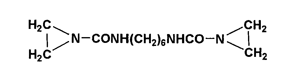
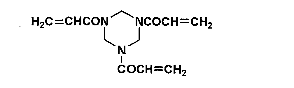
Substrate 2 was prepared similarly to the foregoing
substrate 1, except that a 175 µm thick blue-tinted
transparent PET film used for radiographic material was used.
The transmission density of the substrate 2 was 0.17.
After the following composition was sufficiently
stirred using a homogenizer and filtered, sublayer coating
solutions were prepared.
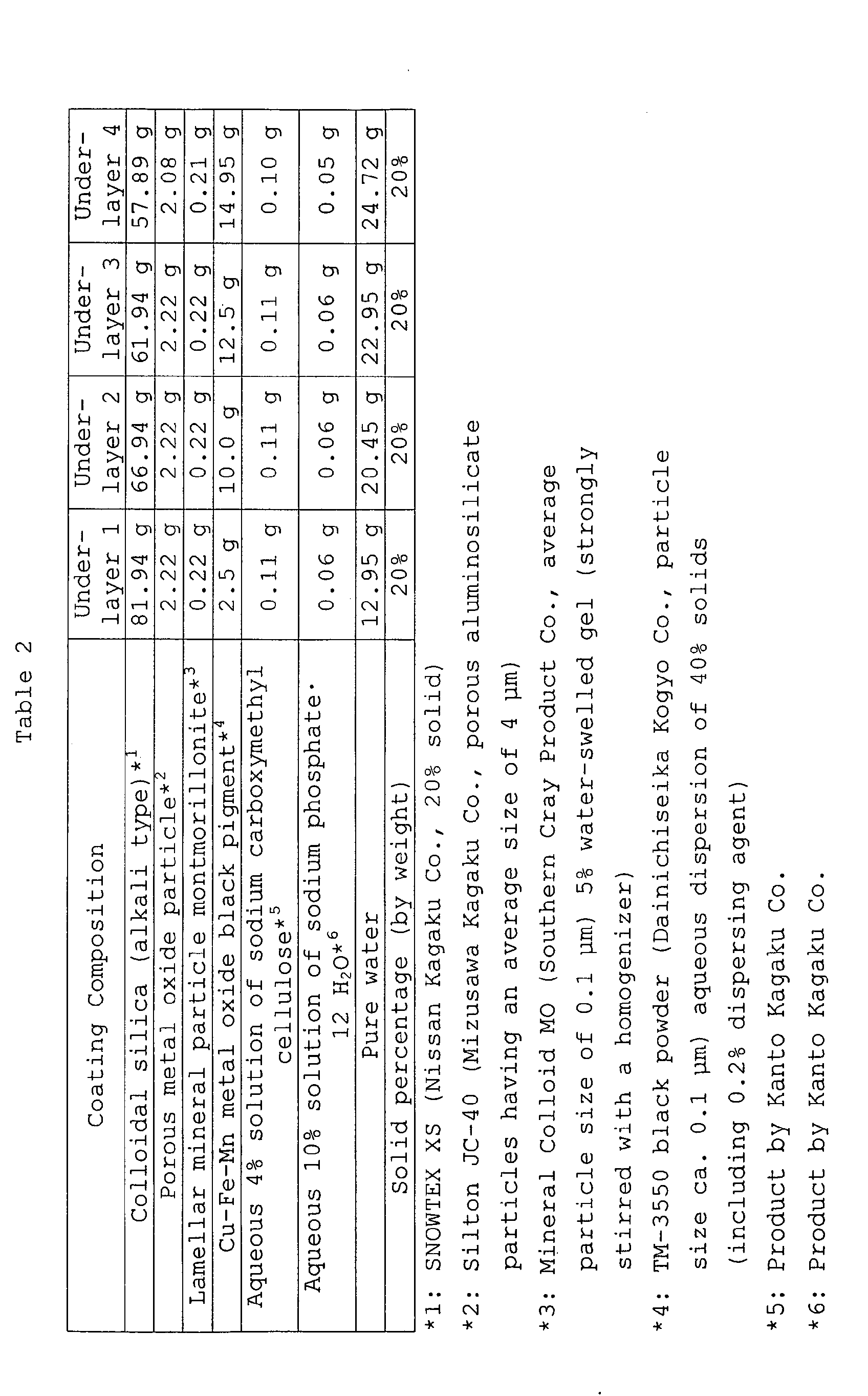 Preparation of hydrophilic layer coating solution
After the following composition was sufficiently
stirred using a homogenizer and filtered, hydrophilic layer
(1) coating solutions was prepared.
| Coating Composition | Hydrophilic Layer (1) |
| Colloidal silica (alkali type) | 10.4 g |
| Necklace-form colloidal silica (alkali type) | 23.4 g |
| Porous metal oxide particle | 1.2 g |
| Porous metal oxide particle | 1.5 g |
| Lamellar mineral particle montmorillonite | 4.8 g |
| Cu-Fe-Mn metal oxide black pigment | 2.7 g |
| Aqueous 4% solution of sodium carboxymethyl cellulose | 3.0 g |
| Aqueous 10% solution of sodium phosphate·12 H2O | 0.6 g |
| Pure water | 52.4 g |
| Solid percentage (by weight) | 12% |
Each of the foregoing under-layer coating solutions was
coated on the substrate 1 or 2 using a #5 wire-bar and
allowed to pass at a speed of 15 m/min through a 15 m long
drying zone set at 100 °C. Subsequently, further thereon,
the hydrophilic layer coating solution described above was
coated using a #4 wire-bar and allowed to pass at a speed of
15 m/min through a 30 m long drying zone set at 100 °C.
Coating amounts of the under-layer and hydrophilic layer were
3.0 g/m2 and 0.55 g/m2. After completion of coating, samples
were aged at 60 °C for one day.
To 5.21 g of pure water were added 0.474 g of EX Color
IR 14 (phthalocyanine dye, product by Nippon Shokubai Co.),
1.2 g of 10% aqueous solution of PVA (PVA 217, product by
KURARAY CO. LTD.) and 0.12 g of an aqueous 5% solution of
surfactant (SF 465, product by Nisshin Kagaku Co.), microbeads
were further added thereto and stirred using a
homogenizer at 8,000 rpm. After removing the microbeads,
9.14 g of pure water was added to obtain an aqueous
dispersion of light-to-heat conversion material (A).
An image forming layer having the composition shown in
Tables 4 and 5 was coated onto the hydrophilic layer using a
#5 wire-bar and allowed to pass at a speed of 15 m/min
through a 30 m long drying zone set at 60 °C. The coating
amount of the image forming layer was 0.5 g/m2.

| Coating Composition | Image Forming Layer | |
| 7 | 8 | |
| carnauba wax emulsion A118 | 9.84 g | 5.12 g |
| carnauba wax emulsion XD-147 | - | 11.81 g |
| PMMA particle: aqueous dispersion of MX 400 | 6.30 g | - |
| light-to-heat conversion material (A): aqueous 3.8% dispersion of IR14 | - | 4.97 g |
| High Micron L-271 | 1.89 g | 1.89 g |
| 10% aqueous solution of disaccharide trehalose powder | 12.6 g | 17.01 g |
| Pure water | 69.37 g | 59.2 g |
| Solid percentage (by weight) | 6.3% | 6.3% |
Printing plate material samples 001 through 011
obtained by combinations of the foregoing substrates, underlayers,
hydrophilic layers and image forming layers are shown
in Table 6, including physical properties thereof.
Using a Macbeth densitometer TD904, the transmission
density of the substrate having an under-layer and a
hydrophilic layer was determined, based on black-and-white
density (visual). Using a glossmeter, the glossiness of the
uppermost surface of the image forming layer of a printing
plate material was measured as the glossiness of the image
forming layer. The measuring angle was 60° with respect to
both incident light and reflection light.
| Sample No. | Undersubstrate layer | Hydrophilic Layer | Transmission Density | Image Forming Layer | Glossiness | Remark | |
| 001 | 1 | 1 | 1 | 0.33 | 1 | 15.0 | Comp. |
| 002 | 1 | 1 | 1 | 0.33 | 4 | 20.0 | Comp. |
| 003 | 2 | 1 | 1 | 0.55 | 3 | 3.2 | Inv. |
| 004 | 1 | 2 | 1 | 0.84 | 1 | 13.0 | Comp. |
| 005 | 2 | 2 | 1 | 0.91 | 2 | 8.4 | Inv. |
| 006 | 1 | 2 | 1 | 0.84 | 3 | 1.2 | Inv. |
| 007 | 1 | 2 | 1 | 0.84 | 5 | 5.6 | Inv. |
| 008 | 1 | 2 | 1 | 0.84 | 8 | 4.0 | Inv. |
| 009 | 1 | 3 | 1 | 0.94 | 3 | 0.8 | Inv. |
| 010 | 1 | 3 | 1 | 0.94 | 6 | 6.1 | Inv. |
| 011 | 1 | 3 | 1 | 0.94 | 7 | 11.2 | Comp. |
Printing plate material samples were each wound around
an exposing drum. Exposure was conducted using a laser beam
of an 18 µm spot diameter and an 830 nm wavelength. Image
formation was carried out at 2400 dpi (dot number per 2.54
cm) and 175 lines under the exposure energy of 100, 150, 200,
250 and 300 mj/cm2 to obtain printing plates 001 through 011.
Printing
The thus exposed printing plates were each set on a
plate cylinder of a printing machine DAIYA 1F-1 (Mitsubishi
Jukogyo Co., Ltd.) and printing was conducted using coated
paper and aqueous dampening liquid Astro Mark 3 (2 wt%,
available from Nikken Kagaku Kenkyusho) and ink (Toyo King
Highecho M magenta, available from Toyo Ink Seizo Co., Ltd.).
The sequence at the start of printing was carried out at a
printing sequence of a PS plate and specific development on
press was not done.
Using a Macbeth dot meter, a 100th print sample from
the start of printing was measured with respect to
reproduction of 50% dots of imaged areas and an energy value
at which a measured value of 49% to 51% was observed was
defined as proper sensitivity.
The exposed printing plate material was placed with the
image forming layer upward and evaluated visually or using a
magnifier with respect to image visibility after exposure,
while being illuminated with white light. Results are shown
in Table 7. Evaluation was made based on the following
criteria,
Using Gretag SPM100, the difference (ΔE) in Lab value
between exposed and unexposed areas was determined, which was
determined from the Lab values obtained in measurements on a
white background in the manner described earlier.
| No. | Sensitivity (mJ/cm2) | Image Visibility | ΔE | |
| Visual | Magnifier | |||
| 001 | 300 | C | C | 0.77 |
| 002 | 200 | D | D | 0.12 |
| 003 | 250 | B | B | 7.23 |
| 004 | 200 | D | D | 5.91 |
| 005 | 200 | B | B | 9.03 |
| 006 | 200 | A | A | 13.09 |
| 007 | 250 | B | B | 7.57 |
| 008 | 100 | B | B | 7.84 |
| 009 | 150 | A | A | 18.91 |
| 010 | 100 | A | A | 13.25 |
| 011 | 150 | C | D | 4.21 |
According to this invention, printing plate materials
exhibiting superior visibility were obtained even in a
printing plate material having a flexible support (PET).
Claims (20)
- A lithographic printing plate material comprising a flexible support having thereon a hydrophilic layer and an image forming layer, wherein the flexible support having the hydrophilic layer exhibits a transmission density of 0.5 to 1.2, and the outermost surface of an unexposed area of the image forming layer exhibiting a glossiness of 0.1 to 10.
- The material as claimed in claim 1, wherein the image forming layer contains a heat-melting material exhibiting a melting point of 40 to 300 °C.
- The material as claimed in claim 2, wherein the heat-melting material is at least one selected from the group consisting of a paraffin, a polyolefin, a polyethylene wax, a microcrystalline wax and a fatty acid wax.
- The material as claimed in claim 2 or 3, wherein the heat-melting material is comprised of particles having an average particle size of 0.4 to 3.0 µm.
- The material as claimed in any of claims 1 to 4, wherein the image forming layer contains thermoplastic polymer particles.
- The material as claimed in any of claims 1 to 5, wherein the support is colored.
- The material as claimed in any of claims 1 to 6, wherein the material exhibits a difference in La*b* value obtained in white backing between exposed and unexposed areas (ΔE) of 6 to 20.
- The material as claimed in any of claims 1 to 7, wherein the image forming layer contains an oligosaccharide.
- The material as claimed in any of claims 1 to 8, wherein the hydrophilic layer contains metal oxide particles.
- The material as claimed in any of claims 1 to 9, wherein the support further has an underlayer below the hydrophilic layer and at least one of the image forming layer, the hydrophilic layer and the underlayer contains a light-to-heat conversion material.
- A printing method comprising:wherein the printing plate material comprises a flexible support having thereon a hydrophilic layer and an image forming layer, and the flexible support having the hydrophilic layer exhibiting a transmission density of 0.5 to 1.2 and the outermost surface of an unexposed area of the image forming layer exhibiting a glossiness of 0.1 to 10.(a) exposing a printing plate material to a laser or an infrared ray based on image information and(b) performing printing with supplying an aqueous dampening liquid and an ink to the exposed printing plate material,
- The method as claimed in claim 11, wherein the image forming layer contains a heat-melting material exhibiting a melting point of 40 to 300 °C.
- The method as claimed in claim 12, wherein the heat-melting material is at least one selected from the group consisting of a paraffin, a polyolefin, a polyethylene wax, a microcrystalline wax and a fatty acid wax.
- The method as claimed in claim 12, wherein the heat-melting material is comprised of particles having an average particle size of 0.4 to 3.0 µm.
- The method as claimed in any of claims 11 to 14, wherein the image forming layer contains thermoplastic polymer particles.
- The method as claimed in any of claims 11 to 15, wherein the support is colored.
- The method as claimed in any of claims 11 to 16, wherein the material exhibits a difference in La*b* value obtained in white backing between exposed and unexposed areas (ΔE) of 6 to 20.
- The method as claimed in any of claims 11 to 17, wherein the image forming layer contains an oligosaccharide.
- The method as claimed in any of claims 11 to 18, wherein the hydrophilic layer contains metal oxide particles.
- The method as claimed in any of claims 11 to 19, wherein the support further has an underlayer below the hydrophilic layer and at least one of the image forming layer, the hydrophilic layer and the underlayer contains a light-to-heat conversion material.
Applications Claiming Priority (2)
| Application Number | Priority Date | Filing Date | Title |
|---|---|---|---|
| JP2003077663 | 2003-03-20 | ||
| JP2003077663A JP2004284142A (en) | 2003-03-20 | 2003-03-20 | Printing plate material and printing method |
Publications (1)
| Publication Number | Publication Date |
|---|---|
| EP1468821A1 true EP1468821A1 (en) | 2004-10-20 |
Family
ID=32905947
Family Applications (1)
| Application Number | Title | Priority Date | Filing Date |
|---|---|---|---|
| EP04006351A Withdrawn EP1468821A1 (en) | 2003-03-20 | 2004-03-17 | Lithographic printing plate material and printing method |
Country Status (3)
| Country | Link |
|---|---|
| US (1) | US7214468B2 (en) |
| EP (1) | EP1468821A1 (en) |
| JP (1) | JP2004284142A (en) |
Cited By (3)
| Publication number | Priority date | Publication date | Assignee | Title |
|---|---|---|---|---|
| EP1518711A3 (en) * | 2003-09-24 | 2005-10-12 | Konica Minolta Medical & Graphic Inc. | Planographic printing plate material and printing process |
| EP1619024A1 (en) * | 2004-07-21 | 2006-01-25 | Konica Minolta Medical & Graphic, Inc. | Planographic printing plate material, planographic printing plate, and printing process employing the same |
| EP1810836A4 (en) * | 2004-10-26 | 2008-01-23 | Mitsui Chemicals Inc | Lithographic printing plate |
Families Citing this family (9)
| Publication number | Priority date | Publication date | Assignee | Title |
|---|---|---|---|---|
| JP2008031414A (en) * | 2006-07-04 | 2008-02-14 | Fujifilm Corp | Laser decomposable resin composition and pattern forming material using the same |
| JP5238292B2 (en) * | 2007-03-23 | 2013-07-17 | 三菱製紙株式会社 | Water-developable photosensitive lithographic printing plate material |
| US8053162B2 (en) * | 2008-06-17 | 2011-11-08 | Eastman Kodak Company | Substrate and imageable element with hydrophilic interlayer |
| US20100075118A1 (en) * | 2008-09-24 | 2010-03-25 | Fujifilm Corporation | Resin composition for laser engraving, relief printing plate precursor for laser engraving, relief printing plate and method of producing the same |
| TWI523768B (en) | 2010-04-20 | 2016-03-01 | 米蘭集團公司 | Substrate for lithographic printing plate |
| US8758560B2 (en) * | 2011-03-04 | 2014-06-24 | The Procter & Gamble Company | Web substrates having wide color gamut indicia printed thereon |
| CN103818098B (en) * | 2014-01-28 | 2015-09-23 | 太仓丽盛制版有限公司 | The evaluation method of technique roller technological parameter |
| EP3747661A4 (en) * | 2018-01-31 | 2021-04-14 | FUJIFILM Corporation | Lithographic plate original plate, and method for producing lithographic plate |
| FR3102941B1 (en) * | 2019-11-08 | 2022-06-24 | Commissariat Energie Atomique | METHOD OF PROTECTING OBJECTS SENSITIVE TO AIR OR EVAPORATION |
Citations (3)
| Publication number | Priority date | Publication date | Assignee | Title |
|---|---|---|---|---|
| EP1266751A2 (en) * | 2001-06-14 | 2002-12-18 | Konica Corporation | Printing plate precursor, image forming method employing the same, and printing method |
| EP1334842A2 (en) * | 2002-02-12 | 2003-08-13 | Konica Corporation | Printing plate precursor and printing plate |
| EP1334841A2 (en) * | 2002-02-06 | 2003-08-13 | Konica Corporation | Planographic printing plate precursor and printing method employing the same |
Family Cites Families (5)
| Publication number | Priority date | Publication date | Assignee | Title |
|---|---|---|---|---|
| US6110644A (en) * | 1995-10-24 | 2000-08-29 | Agfa-Gevaert, N.V. | Method for making a lithographic printing plate involving on press development |
| JP4015344B2 (en) * | 2000-04-14 | 2007-11-28 | 富士フイルム株式会社 | Master for lithographic printing plate |
| JP2001334766A (en) * | 2000-05-30 | 2001-12-04 | Konica Corp | Planographic original plate and manufacturing method for the same |
| JP2004223833A (en) * | 2003-01-22 | 2004-08-12 | Konica Minolta Holdings Inc | Printing method for using lithographic printing plate material |
| JP2005096169A (en) * | 2003-09-24 | 2005-04-14 | Konica Minolta Medical & Graphic Inc | Lithographic printing plate material and printing method |
-
2003
- 2003-03-20 JP JP2003077663A patent/JP2004284142A/en active Pending
-
2004
- 2004-03-10 US US10/797,870 patent/US7214468B2/en not_active Expired - Fee Related
- 2004-03-17 EP EP04006351A patent/EP1468821A1/en not_active Withdrawn
Patent Citations (3)
| Publication number | Priority date | Publication date | Assignee | Title |
|---|---|---|---|---|
| EP1266751A2 (en) * | 2001-06-14 | 2002-12-18 | Konica Corporation | Printing plate precursor, image forming method employing the same, and printing method |
| EP1334841A2 (en) * | 2002-02-06 | 2003-08-13 | Konica Corporation | Planographic printing plate precursor and printing method employing the same |
| EP1334842A2 (en) * | 2002-02-12 | 2003-08-13 | Konica Corporation | Printing plate precursor and printing plate |
Cited By (3)
| Publication number | Priority date | Publication date | Assignee | Title |
|---|---|---|---|---|
| EP1518711A3 (en) * | 2003-09-24 | 2005-10-12 | Konica Minolta Medical & Graphic Inc. | Planographic printing plate material and printing process |
| EP1619024A1 (en) * | 2004-07-21 | 2006-01-25 | Konica Minolta Medical & Graphic, Inc. | Planographic printing plate material, planographic printing plate, and printing process employing the same |
| EP1810836A4 (en) * | 2004-10-26 | 2008-01-23 | Mitsui Chemicals Inc | Lithographic printing plate |
Also Published As
| Publication number | Publication date |
|---|---|
| US7214468B2 (en) | 2007-05-08 |
| US20040185377A1 (en) | 2004-09-23 |
| JP2004284142A (en) | 2004-10-14 |
Similar Documents
| Publication | Publication Date | Title |
|---|---|---|
| US6596462B2 (en) | Printing plate element and preparation method of printing plate | |
| US6737220B2 (en) | Printing method and printing press | |
| US20060019196A1 (en) | Planographic printing plate material, planographic printing plate, and printing process employing the same | |
| US7214468B2 (en) | Lithographic printing plate material and printing method | |
| EP1808292B1 (en) | Printing plate precursor, image forming method employing the same, and printing method | |
| EP1564020A1 (en) | Printing plate precursor material | |
| US6688228B2 (en) | Planographic printing plate precursor having a support with pits | |
| US20050064339A1 (en) | Planographic printing plate material and printing process | |
| EP1403040B1 (en) | Printing plate material and image formation method employing the same | |
| US7140297B2 (en) | Printing process and manufacturing process of printing plate material | |
| US7147988B2 (en) | Printing plate material, roll of a printing plate material and printing method | |
| JP2001232746A (en) | Method for manufacturing printing plate | |
| JP4048872B2 (en) | Plate inspection method for printing plate materials | |
| JP4168681B2 (en) | Printing plate material and printing plate | |
| JP4182713B2 (en) | Printing plate material | |
| JP2004167904A (en) | Printing plate material and printing plate | |
| US20080118859A1 (en) | Planographic Printing Plate Material and Planographic Printing Process | |
| JP2004050616A (en) | Printing plate material and printing method | |
| JP2003312157A (en) | Lithographic printing plate material | |
| JP2003159881A (en) | Printing plate material and method for manufacturing printing plate material | |
| JP2005088454A (en) | Printing method for lithographic printing plate | |
| JP2008149467A (en) | Lithographic printing plate material and printing method | |
| JP2005059460A (en) | Printing plate material and method for printing it | |
| JP2004034502A (en) | Image forming method and printing method with printing plate material | |
| JP2005067014A (en) | Lithographic printing plate material, image recording method, printing plate making method and printing method |
Legal Events
| Date | Code | Title | Description |
|---|---|---|---|
| PUAI | Public reference made under article 153(3) epc to a published international application that has entered the european phase |
Free format text: ORIGINAL CODE: 0009012 |
|
| AK | Designated contracting states |
Kind code of ref document: A1 Designated state(s): AT BE BG CH CY CZ DE DK EE ES FI FR GB GR HU IE IT LI LU MC NL PL PT RO SE SI SK TR |
|
| AX | Request for extension of the european patent |
Extension state: AL LT LV MK |
|
| 17P | Request for examination filed |
Effective date: 20050329 |
|
| AKX | Designation fees paid |
Designated state(s): DE FR GB IT |
|
| STAA | Information on the status of an ep patent application or granted ep patent |
Free format text: STATUS: THE APPLICATION HAS BEEN WITHDRAWN |
|
| 18W | Application withdrawn |
Effective date: 20080925 |