EP1468357B1 - Panel guide and impact separation system for a sliding door - Google Patents
Panel guide and impact separation system for a sliding door Download PDFInfo
- Publication number
- EP1468357B1 EP1468357B1 EP02805176A EP02805176A EP1468357B1 EP 1468357 B1 EP1468357 B1 EP 1468357B1 EP 02805176 A EP02805176 A EP 02805176A EP 02805176 A EP02805176 A EP 02805176A EP 1468357 B1 EP1468357 B1 EP 1468357B1
- Authority
- EP
- European Patent Office
- Prior art keywords
- door
- guide
- door panel
- elongate beam
- panel
- Prior art date
- Legal status (The legal status is an assumption and is not a legal conclusion. Google has not performed a legal analysis and makes no representation as to the accuracy of the status listed.)
- Expired - Lifetime
Links
- 238000000926 separation method Methods 0.000 title description 9
- 230000014759 maintenance of location Effects 0.000 claims description 36
- 239000006260 foam Substances 0.000 claims description 6
- 239000012858 resilient material Substances 0.000 claims description 4
- 238000004891 communication Methods 0.000 claims description 2
- 230000008878 coupling Effects 0.000 claims 1
- 238000010168 coupling process Methods 0.000 claims 1
- 238000005859 coupling reaction Methods 0.000 claims 1
- 239000000463 material Substances 0.000 description 10
- 230000007246 mechanism Effects 0.000 description 6
- 238000003860 storage Methods 0.000 description 3
- 238000009826 distribution Methods 0.000 description 2
- 238000007789 sealing Methods 0.000 description 2
- 230000000712 assembly Effects 0.000 description 1
- 238000000429 assembly Methods 0.000 description 1
- 230000006835 compression Effects 0.000 description 1
- 238000007906 compression Methods 0.000 description 1
- 238000010276 construction Methods 0.000 description 1
- 230000001186 cumulative effect Effects 0.000 description 1
- 230000007613 environmental effect Effects 0.000 description 1
- 238000009413 insulation Methods 0.000 description 1
- 238000004519 manufacturing process Methods 0.000 description 1
- 239000002184 metal Substances 0.000 description 1
- 230000004048 modification Effects 0.000 description 1
- 238000012986 modification Methods 0.000 description 1
- 238000005096 rolling process Methods 0.000 description 1
- 229920002994 synthetic fiber Polymers 0.000 description 1
- 239000002023 wood Substances 0.000 description 1
Images





Classifications
-
- E—FIXED CONSTRUCTIONS
- E05—LOCKS; KEYS; WINDOW OR DOOR FITTINGS; SAFES
- E05D—HINGES OR SUSPENSION DEVICES FOR DOORS, WINDOWS OR WINGS
- E05D15/00—Suspension arrangements for wings
- E05D15/06—Suspension arrangements for wings for wings sliding horizontally more or less in their own plane
- E05D15/0621—Details, e.g. suspension or supporting guides
- E05D15/0626—Details, e.g. suspension or supporting guides for wings suspended at the top
- E05D15/063—Details, e.g. suspension or supporting guides for wings suspended at the top on wheels with fixed axis
-
- E—FIXED CONSTRUCTIONS
- E05—LOCKS; KEYS; WINDOW OR DOOR FITTINGS; SAFES
- E05D—HINGES OR SUSPENSION DEVICES FOR DOORS, WINDOWS OR WINGS
- E05D15/00—Suspension arrangements for wings
- E05D15/06—Suspension arrangements for wings for wings sliding horizontally more or less in their own plane
- E05D15/0621—Details, e.g. suspension or supporting guides
- E05D15/0626—Details, e.g. suspension or supporting guides for wings suspended at the top
- E05D15/0656—Bottom guides
-
- E—FIXED CONSTRUCTIONS
- E06—DOORS, WINDOWS, SHUTTERS, OR ROLLER BLINDS IN GENERAL; LADDERS
- E06B—FIXED OR MOVABLE CLOSURES FOR OPENINGS IN BUILDINGS, VEHICLES, FENCES OR LIKE ENCLOSURES IN GENERAL, e.g. DOORS, WINDOWS, BLINDS, GATES
- E06B9/00—Screening or protective devices for wall or similar openings, with or without operating or securing mechanisms; Closures of similar construction
- E06B9/56—Operating, guiding or securing devices or arrangements for roll-type closures; Spring drums; Tape drums; Counterweighting arrangements therefor
- E06B9/58—Guiding devices
- E06B9/581—Means to prevent or induce disengagement of shutter from side rails
-
- E—FIXED CONSTRUCTIONS
- E05—LOCKS; KEYS; WINDOW OR DOOR FITTINGS; SAFES
- E05D—HINGES OR SUSPENSION DEVICES FOR DOORS, WINDOWS OR WINGS
- E05D15/00—Suspension arrangements for wings
- E05D15/06—Suspension arrangements for wings for wings sliding horizontally more or less in their own plane
- E05D15/0621—Details, e.g. suspension or supporting guides
- E05D15/0626—Details, e.g. suspension or supporting guides for wings suspended at the top
- E05D15/0647—Details, e.g. suspension or supporting guides for wings suspended at the top on sliding blocks
-
- E—FIXED CONSTRUCTIONS
- E05—LOCKS; KEYS; WINDOW OR DOOR FITTINGS; SAFES
- E05Y—INDEXING SCHEME ASSOCIATED WITH SUBCLASSES E05D AND E05F, RELATING TO CONSTRUCTION ELEMENTS, ELECTRIC CONTROL, POWER SUPPLY, POWER SIGNAL OR TRANSMISSION, USER INTERFACES, MOUNTING OR COUPLING, DETAILS, ACCESSORIES, AUXILIARY OPERATIONS NOT OTHERWISE PROVIDED FOR, APPLICATION THEREOF
- E05Y2900/00—Application of doors, windows, wings or fittings thereof
-
- E—FIXED CONSTRUCTIONS
- E05—LOCKS; KEYS; WINDOW OR DOOR FITTINGS; SAFES
- E05Y—INDEXING SCHEME ASSOCIATED WITH SUBCLASSES E05D AND E05F, RELATING TO CONSTRUCTION ELEMENTS, ELECTRIC CONTROL, POWER SUPPLY, POWER SIGNAL OR TRANSMISSION, USER INTERFACES, MOUNTING OR COUPLING, DETAILS, ACCESSORIES, AUXILIARY OPERATIONS NOT OTHERWISE PROVIDED FOR, APPLICATION THEREOF
- E05Y2900/00—Application of doors, windows, wings or fittings thereof
- E05Y2900/10—Application of doors, windows, wings or fittings thereof for buildings or parts thereof
- E05Y2900/102—Application of doors, windows, wings or fittings thereof for buildings or parts thereof for cold-rooms
-
- E—FIXED CONSTRUCTIONS
- E05—LOCKS; KEYS; WINDOW OR DOOR FITTINGS; SAFES
- E05Y—INDEXING SCHEME ASSOCIATED WITH SUBCLASSES E05D AND E05F, RELATING TO CONSTRUCTION ELEMENTS, ELECTRIC CONTROL, POWER SUPPLY, POWER SIGNAL OR TRANSMISSION, USER INTERFACES, MOUNTING OR COUPLING, DETAILS, ACCESSORIES, AUXILIARY OPERATIONS NOT OTHERWISE PROVIDED FOR, APPLICATION THEREOF
- E05Y2900/00—Application of doors, windows, wings or fittings thereof
- E05Y2900/10—Application of doors, windows, wings or fittings thereof for buildings or parts thereof
- E05Y2900/106—Application of doors, windows, wings or fittings thereof for buildings or parts thereof for garages
-
- E—FIXED CONSTRUCTIONS
- E05—LOCKS; KEYS; WINDOW OR DOOR FITTINGS; SAFES
- E05Y—INDEXING SCHEME ASSOCIATED WITH SUBCLASSES E05D AND E05F, RELATING TO CONSTRUCTION ELEMENTS, ELECTRIC CONTROL, POWER SUPPLY, POWER SIGNAL OR TRANSMISSION, USER INTERFACES, MOUNTING OR COUPLING, DETAILS, ACCESSORIES, AUXILIARY OPERATIONS NOT OTHERWISE PROVIDED FOR, APPLICATION THEREOF
- E05Y2900/00—Application of doors, windows, wings or fittings thereof
- E05Y2900/10—Application of doors, windows, wings or fittings thereof for buildings or parts thereof
- E05Y2900/13—Type of wing
- E05Y2900/132—Doors
-
- E—FIXED CONSTRUCTIONS
- E06—DOORS, WINDOWS, SHUTTERS, OR ROLLER BLINDS IN GENERAL; LADDERS
- E06B—FIXED OR MOVABLE CLOSURES FOR OPENINGS IN BUILDINGS, VEHICLES, FENCES OR LIKE ENCLOSURES IN GENERAL, e.g. DOORS, WINDOWS, BLINDS, GATES
- E06B9/00—Screening or protective devices for wall or similar openings, with or without operating or securing mechanisms; Closures of similar construction
- E06B9/56—Operating, guiding or securing devices or arrangements for roll-type closures; Spring drums; Tape drums; Counterweighting arrangements therefor
- E06B9/58—Guiding devices
- E06B2009/585—Emergency release to prevent damage of shutter or guiding device
Definitions
- the invention relates to a high-speed, sliding industrial door.
- Sliding doors have been used for many years to secure various enclosures, including those for cold storage facilities in manufacturing plants, warehouses, garages, and other industrial rooms. It is known in the art that door panels used in connection with such rooms are constructed from light-weight foam. The light-weight foam panels provide the insulation necessary to maintain the temperature objectives of such rooms. Such panels also permit the doors to be opened and closed at high speeds, thereby minimizing exposure of the contents of the room while the door is opened.
- DE 298 08 179 U discloses a sliding door with door panels each comprising a door leaf made from a flexible synthetic material a frame surrounding the door leaf.
- the door panels are guided at the top and at the bottom with the help of transverse struts.
- a stiffening rail engages with a guide which is attached to the wall. The stiffening rail ends immediately in front the trailing edges of the door panels.
- the present invention is provided so solve the problems discussed above and other problems, and to provide advantages not provided by prior doors of this type.
- FIG. 1 shows an automatic bi-parting sliding door 10 incorporating the guide system 12 of the present invention.
- the door 10 is generally installed about an opening.
- Opening generally refers to any passage or throughway defined in a general manner by a upper extent, a lower extent and one or more wall edges or other frame-like structures. It is contemplated that opening with which the present invention is employed be a doorway as typically found in a wall of a building or the like.
- the present door can also be installed in a vestibule, which extends away from a doorway. Such vestibules are typically used in applications where it is necessary to minimize the exposure of an interior space to rapid fluctuations in pressure, temperature or other environmental considerations.
- the door 10 with which the guide system 12 is used generally comprises at least one door panel 14. As seen in FIGS.1 , each door panel 14 has a leading edge 13 and a trailing edge 15, and is adapted to laterally translate along a plane relative to the opening between an open position and a closed position. According to the present invention, the door panels 14 have a substantially linear opening and closing direction of travel. However, it is contemplated that the travel of the door panels 14 between the open and closed positions may be slightly non-linear to compensate for seals on the leading edge 13 of the door 10 or for other reasons deemed necessary for operation of the door 10.
- Door panels 14 used in connection with the present invention may be designed in a variety of sizes and may be constructed from any number of materials.
- the door panels 14 may be made from foam or other materials suitable for maintaining cold and heat differentials on opposed sides of the panels.
- the present invention is not limited to use with foam door panels. Instead the present invention may be used with any door panel 14 of material suitable for a particular application, including wood, metal and various polymeric materials.
- Each door panel 14 should be approximately equal to one-half the width of the opening, and of a height approximately equal to the opening height. With a single sliding door panel design, the door panel 14 is preferably of the same approximate height and width of the opening. However, the use of greater than two door panels 14 is also contemplated, and the modification of the presently disclosed invention to accommodate such design variations would naturally be readily understood by those skilled in the art after studying this disclosure, without requiring undue experimentation. Where certain applications may require, it is contemplated by the present invention that the cumulative size of all door panels 14 in a single application could be significantly less than, or significantly more than the size of the opening.
- a motor 16 and a drive system 18 are employed in connection with the doors 10 described herein.
- a motor 16 is operably coupled to a drive system 18 for actuating the door panel 14 between the open and closed positions on an overhead track.
- the present invention may utilize drive motor 16 of the type manufactured by SEW-Eurodrive and marketed under the trade name a SEW-Eurodrive MOVIMOT ® .
- doors used in connection with the present system may employ any drive motor 16 that is capable of at least bi-directional, two-speed operation.
- the door of the present invention may also include a controller 19 that is in electronic communication with the motor 16.
- the controller 19 may be any type suitable for use with door assemblies, and which are adapted to control the starting, stopping, speed and direction of the motor 16. It is contemplated, however, that the present invention be employed in an application wherein the door panel 14 is manually moved between the opened and closed positions.
- the guide system 12 of the present invention provides several advantages over prior art systems.
- the guide system 12 disclosed herein acts to maintain the actuating door panel 14 in close proximity to the surrounding wall or mounting surface 20 throughout substantially its entire path of travel.
- the guide system 12 is adapted to accommodate and incorporate breakaway features, if so desired.
- the guide system 12 also provides a point at which forces applied to semi-flexible door panel 14 may be concentrated and thus provides predictability in the distribution of the forces in the door.
- the guide system 12 generally comprises a guide 22 and a guide follower 24.
- the guide 22 is mounted to a mounting surface 20 located between the upper and lower extent of the opening.
- the mounting surface 20 may be a wall surrounding a doorway, or a freestanding surface such as that used in connection with a vestibule.
- the guide 22 may be any surface suitable for accommodating generally linear travel of the door panel 14 between an open and closed position.
- the guide 22 may be a plate, a rod, a bar, a u-shaped track, a v-shaped track, or a c-shaped track.
- the present invention should not be limited to the geometric configurations specifically described or shown herein, as any geometric configuration that provides a generally linear guide path of travel for the door panel 14 may be employed without departing from the present invention.
- the guide follower 24 is pivotally attached to the door panel 14.
- the guide follower 24 may be attached to the door panel 14 by any suitable mechanism that allows for pivoting, including a pin or other fastener.
- the guide follower 24 is disposed in operable engagement with the guide 22 such that, as the door moves between the open and closed positions, the guide follower 24 translates along at least a portion of the guide 22.
- the guide follower 24 is comprised of a retention block 26 and a retention tab 28.
- the retention block 26 has a first end 26a, a second end 26b and a throughway 30 disposed proximate the first end 26a.
- the throughway 30 provides a pivot point for pivotable connection of the guide follower 24 to the door panel 14.
- the retention tab 28 has a first end 28a and a second end 28b.
- the first end 28a of the retention tab 28 is connected proximate the second end 26b of the retention block 26.
- the second end 28b of the retention tab 28 extends generally perpendicular to the retention block 26 and has a channel 32 formed proximate its distal end.
- the channel 32 engages the guide 22 so that there may exist relative sliding between the guide follower 24 and guide 22.
- at least the retention tab 28 is made from a low friction polymeric material to assist sliding engagement of the guide follower 24 and the guide 22.
- the guide follower 24 is pivotally biased around an axis parallel to the lateral translation of the door, thereby forcing the guide follower 24 into operable engagement with the guide 22. This allows for substantially continuous engagement between the guide follower 24 and the guide 22 throughout the entire linear path of travel of the door panel 14.
- the guide follower 24 can be biased by employing a means for biasing 34.
- the means for biasing 34 is preferably a torsion spring disposed in cooperative engagement with the guide follower 24 and is secured by a clamp 36 and stop mechanism 38. It is contemplated that other biasing mechanisms may be used to bias the guide follower 24, including cams, compression springs, leaf springs, helical springs, elastomeric materials or other suitable biasing mechanisms known to those skilled in the art.
- the guide follower 24 is adapted to disengage the guide 22 when sufficient force is applied to the door panel 14. If the guide follower 24 includes a biasing means 34, such as is described above, the guide follower 24 will disengage the guide 22 when sufficient force is transferred to biasing means 34 to overcome the force that biases the guide follower 24 into engagement with the guide 22.
- the guide follower 24 may be made from a semi-flexible polymeric material. According to one embodiment of the present invention, at least the second end of the retention tab 28 is sufficiently flexible to permit the guide follower 24 to disengage the guide 22 upon receiving an impact in excess of a predetermined force. As shown in FIGS.
- the second end of the retention tab 28 may also be tapered. By tapering the second end of the retention tab 28, less material surrounds the channel 32, thus assisting the retention tab 28 in flexing so that guide follower 24 may more easily disengage the guide 22 upon impact to the door panel 14.
- FIGS. 11-13 illustrate another embodiment of a guide follower 24' that may be used in connection with a guide system 12' of the present invention.
- the guide follower 24' comprises a trolley 40.
- the trolley 40 generally includes a retention block 42 and a roller assembly block 44.
- the retention block 42 is attached to the trailing edge 15 of the door and the roller assembly is coupled to the retention block 42.
- the roller assembly block 44 has at least one roller 46 operably disposed thereon.
- the roller assembly block 44 has a plurality of rollers 46, and at least two of the plurality of rollers 46 engage the guide 22' on opposed sides of the guide 22' so that a channel is formed between the rollers 46.
- the rollers 46 are preferably made from a low friction polymeric material to assist the guide follower 24' in rolling with on the guide 22'.
- the guide follower 24' may also include a resilient material (not shown) disposed between the block and roller assembly.
- a tensioning arm 48 having a pivoting end 50 and a locking end 52 is attached to either the retention block 42 or the roller assembly block 44.
- a clasp adapted to receive the locking end 52 of the tensioning arm 48 is attached to the other of the retention block 42 and the roller assembly block 44.
- the retention block 42 and roller assembly block 44 may be connected one to the other by the tensioning arm 48.
- the resilient material is of sufficient thickness and resiliency such that when it is compressed, the resilient material creates a resistant force between the retention block 42 and the roller assembly block 44.
- rollers 46 of this embodiment of the guide follower 24' may be press fit on their respective roller mounts such that when a force in excess of a predetermined force is applied to a door panel 14 to which this guide follower 24' is connected, the rollers 46 separate from the trolley 40.
- the guide follower 24' may be configured such that the rollers 46 remain attached upon application of a predetermined force to the door panel 14, but the retention block 42 separates from the roller assembly block 44.
- a magnet 56 is attached to either the guide follower 24" or the door panel 14.
- a magnet attracter 58 is attached to the other of the guide follower 24" and the door panel 14. The magnet 56 magnetically engages the attracter 58 and couples the guide follower 24" to the door panel 14. The magnet 56 is separable from the magnet attracter 58 upon an impact to the door panel 14 in excess of a predetermined force, thereby permitting the panel 14 to separate from the guide follower 24".
- the present invention can include an elongate beam 60 which is attached to the door panel 14 between the top and the bottom of the door panel 14.
- a first portion of the elongate beam 60 extends generally horizontally along a vertical plane of the door panel 14.
- a second portion of the elongate beam 60 extends away from the leading edge 13 of the door panel 14 and beyond the trailing edge 15 of the door panel 14.
- the second portion of the elongate beam 60 operably engages the guide 22, 22', 22". It is contemplated that the second portion of the elongate beam 60 engages the guide 22, 22', 22" directly or, as shown in FIGS.
- the elongate beam 60 may have any geometric cross-section without departing from the invention, including for example a cylindrical rod or a rectangular beam. Furthermore, it will be apparent to those of skill that the elongate beam 60 may be of any size suitable for the application with which the door 10 is being use.
- the elongate beam 60 extends across substantially the entire vertical plane of the door panel 14. However, it is contemplated by the present invention that the elongate beam 60 extend across less than the entire vertical plane of the door panel 14. The extent to which the elongate beam 60 extends across the door panel 14 will be dictated by the specific application with which the invention is being used, as well as by the size, material and construction of the door panel 14. It will be readily understood by those of skill in the art, however, that any configuration in which some portion of the beam extends across at least a portion of the vertical plane of the panel, and some portion of the elongate beam 60 extends beyond the trailing edge 15 of the door panel 14 will be suitable for the present invention.
- the first portion of the elongate beam 60 extends through the core of at least a portion of the door panel 14 and the second portion of the elongate beam 60 extends out of the trailing edge 15 of the door panel 14.
- the elongate beam 60 serves to provides stiffness to the door panel 14. Accordingly, the door panel 14 is not only imparted with a degree of stiffness to withstand impact, but the elongate beam 60 also provides improved stiffness to assist in aligning leading edge 13 seals or the like during opening and closing of the door panel 14.
- the elongate beam 60 as used in connection with flexible or semi-flexible door panels 14, also provides a point at which impact forces may be concentrated. This provides predictability in the distribution of the forces in the door, thereby allowing a reliable breakaway mechanism. Additionally, the elongate beam 60 acts to ameliorate stress at the connection between the door panel 14 and the guide system 12, 12', 12" by moving the stress point away from the panel edge to the breakaway mechanism associated with the guide system 12, 12', 12". In so doing, the elongate beam 60 provides integrity to the connection of the door panel 14 to the guide system 12, 12', 12". The elongate beam 60 also reduces damage to the overhead track and minimizes derailment of the door panels 14 from the overhead tracks.
Landscapes
- Engineering & Computer Science (AREA)
- Mechanical Engineering (AREA)
- Structural Engineering (AREA)
- Architecture (AREA)
- Civil Engineering (AREA)
- Wing Frames And Configurations (AREA)
- Power-Operated Mechanisms For Wings (AREA)
- Operating, Guiding And Securing Of Roll- Type Closing Members (AREA)
Description
- The invention relates to a high-speed, sliding industrial door.
- Sliding doors have been used for many years to secure various enclosures, including those for cold storage facilities in manufacturing plants, warehouses, garages, and other industrial rooms. It is known in the art that door panels used in connection with such rooms are constructed from light-weight foam. The light-weight foam panels provide the insulation necessary to maintain the temperature objectives of such rooms. Such panels also permit the doors to be opened and closed at high speeds, thereby minimizing exposure of the contents of the room while the door is opened.
- Inherent to doors used in connection with cold-storage applications are problems associated with air pressure differentials across opposite faces of the door. These differentials tend to push the door panels inward or outward and away from the walls surrounding the door. Air pressure differentials created by a rapidly actuated panel can displace a relatively light panel out of its normal plane of travel. This can result in improper positioning of the door when it reaches its closed position, thereby creating problems with properly sealing the doorway. This can also result in wear and ultimately damage to the hardware associated with the door, including the overhead track.
- Systems such as those in
U.S. Patent No. 6,330,763 to Kern et al. have been developed in an attempt to address some of the issues described above. However, there still exists limitations inherent to such systems. For example, the cord and ring system in Kern et al. does not provide sufficient rigidity to ensure proper sealing of the leading edge of the panels as the door moves to a closed position. Moreover, the system in Kern et al. does not hold the hold panel close to the wall through its entire path of travel. -
DE 298 08 179 U discloses a sliding door with door panels each comprising a door leaf made from a flexible synthetic material a frame surrounding the door leaf. The door panels are guided at the top and at the bottom with the help of transverse struts. Once the door is open, a stiffening rail engages with a guide which is attached to the wall. The stiffening rail ends immediately in front the trailing edges of the door panels. - The present invention is provided so solve the problems discussed above and other problems, and to provide advantages not provided by prior doors of this type.
- The above problems are solved by a sliding door comprising the features of claim 1.
-
-
FIG. 1 is a front view of a sliding door and panel guide and impact separation system according to the present invention; -
FIG. 2 is partial perspective view of a door and panel guide and impact separation system according to the present invention; -
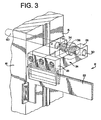
FIG. 3 is partial perspective view of a door and panel guide and impact separation system according to the present invention; -
FIG. 4 is a perspective view of a guide follower according to the present invention; -
FIG. 5 is a side view of the guide follower shown inFIG.4 ; -
FIG. 6 is an end view of the guide follower shown inFIG.4 ; -
FIG. 7 is a top view of the guide follower shown inFIG.4 ; -
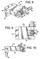
FIG. 8 is a perspective view of a guide follower in connection with a elongate beam according to the present invention; -
FIG. 9 is a top view of the guide follower and a elongate beam shown inFIG. 8 ; -
FIG. 10 is a top view of the guide follower and a elongate beam shown inFIG. 8 ; -
FIG. 11 is partial perspective view of a door and another embodiment of a panel guide and impact separation system according to the present invention; -
FIG. 12 is partial perspective view of another embodiment of a panel guide and impact separation system according to the present invention; -
FIG. 13 is partial perspective view of another embodiment of a panel guide and impact separation system according to the present invention; and, -
FIG. 14 is partial perspective view of a door and another embodiment of a panel guide and impact separation system according to the present invention. - While this invention is susceptible to embodiment in many different forms, there is shown in the drawings, and will herein be described in detail, preferred embodiments of the invention with the understanding that the present disclosure is to be considered as an exemplification of the principles of the invention and is not intended to limit the broad aspect of the invention to the embodiments illustrated.
- The present invention is generally directed to a sliding door 10 which incorporates a panel guide and impact separation system 12 (hereinafter, "the
guide system 12").FIG. 1 shows an automatic bi-parting sliding door 10 incorporating theguide system 12 of the present invention. As shown inFIG. 1 the door 10 is generally installed about an opening. "Opening" generally refers to any passage or throughway defined in a general manner by a upper extent, a lower extent and one or more wall edges or other frame-like structures. It is contemplated that opening with which the present invention is employed be a doorway as typically found in a wall of a building or the like. However, the present door can also be installed in a vestibule, which extends away from a doorway. Such vestibules are typically used in applications where it is necessary to minimize the exposure of an interior space to rapid fluctuations in pressure, temperature or other environmental considerations. - The door 10 with which the
guide system 12 is used generally comprises at least onedoor panel 14. As seen inFIGS.1 , eachdoor panel 14 has a leadingedge 13 and atrailing edge 15, and is adapted to laterally translate along a plane relative to the opening between an open position and a closed position. According to the present invention, thedoor panels 14 have a substantially linear opening and closing direction of travel. However, it is contemplated that the travel of thedoor panels 14 between the open and closed positions may be slightly non-linear to compensate for seals on the leadingedge 13 of the door 10 or for other reasons deemed necessary for operation of the door 10. -
Door panels 14 used in connection with the present invention may be designed in a variety of sizes and may be constructed from any number of materials. For example, in cold storage applications thedoor panels 14 may be made from foam or other materials suitable for maintaining cold and heat differentials on opposed sides of the panels. However, it would be readily understood by those of skill, that the present invention is not limited to use with foam door panels. Instead the present invention may be used with anydoor panel 14 of material suitable for a particular application, including wood, metal and various polymeric materials. - Each
door panel 14 should be approximately equal to one-half the width of the opening, and of a height approximately equal to the opening height. With a single sliding door panel design, thedoor panel 14 is preferably of the same approximate height and width of the opening. However, the use of greater than twodoor panels 14 is also contemplated, and the modification of the presently disclosed invention to accommodate such design variations would naturally be readily understood by those skilled in the art after studying this disclosure, without requiring undue experimentation. Where certain applications may require, it is contemplated by the present invention that the cumulative size of alldoor panels 14 in a single application could be significantly less than, or significantly more than the size of the opening. - All remaining discussions will be directed to a single sliding door panel design, but it is understood that such discussion will also be applicable to multi-panel sliding
door panels 14 and the particular design variations mentioned. These types of doors are well known in the art and application of the following discussion to such doors will be readily understood by those skilled in the art. - Typically, a
motor 16 and adrive system 18 are employed in connection with the doors 10 described herein. Specifically, as shown inFIG. 1 , amotor 16 is operably coupled to adrive system 18 for actuating thedoor panel 14 between the open and closed positions on an overhead track. For example, the present invention may utilizedrive motor 16 of the type manufactured by SEW-Eurodrive and marketed under the trade name a SEW-Eurodrive MOVIMOT®. However, doors used in connection with the present system may employ anydrive motor 16 that is capable of at least bi-directional, two-speed operation. The door of the present invention may also include acontroller 19 that is in electronic communication with themotor 16. Thecontroller 19 may be any type suitable for use with door assemblies, and which are adapted to control the starting, stopping, speed and direction of themotor 16. It is contemplated, however, that the present invention be employed in an application wherein thedoor panel 14 is manually moved between the opened and closed positions. - The
guide system 12 of the present invention provides several advantages over prior art systems. For example, theguide system 12 disclosed herein acts to maintain theactuating door panel 14 in close proximity to the surrounding wall or mountingsurface 20 throughout substantially its entire path of travel. Additionally, theguide system 12 is adapted to accommodate and incorporate breakaway features, if so desired. Theguide system 12 also provides a point at which forces applied tosemi-flexible door panel 14 may be concentrated and thus provides predictability in the distribution of the forces in the door. Theguide system 12 and its additional advantages will now be described below in further detail. - As may be seen in
FIGS. 1-14 , theguide system 12 generally comprises aguide 22 and aguide follower 24. Theguide 22 is mounted to a mountingsurface 20 located between the upper and lower extent of the opening. As discussed above, the mountingsurface 20 may be a wall surrounding a doorway, or a freestanding surface such as that used in connection with a vestibule. Theguide 22 may be any surface suitable for accommodating generally linear travel of thedoor panel 14 between an open and closed position. For example, theguide 22 may be a plate, a rod, a bar, a u-shaped track, a v-shaped track, or a c-shaped track. The present invention, however, should not be limited to the geometric configurations specifically described or shown herein, as any geometric configuration that provides a generally linear guide path of travel for thedoor panel 14 may be employed without departing from the present invention. - As may be seen in
FIGS. 2 and3 , theguide follower 24 is pivotally attached to thedoor panel 14. Theguide follower 24 may be attached to thedoor panel 14 by any suitable mechanism that allows for pivoting, including a pin or other fastener. Theguide follower 24 is disposed in operable engagement with theguide 22 such that, as the door moves between the open and closed positions, theguide follower 24 translates along at least a portion of theguide 22. - According to one embodiment of the present invention shown in
FIG. 2-10 , theguide follower 24 is comprised of aretention block 26 and aretention tab 28. Theretention block 26 has afirst end 26a, asecond end 26b and athroughway 30 disposed proximate thefirst end 26a. Thethroughway 30 provides a pivot point for pivotable connection of theguide follower 24 to thedoor panel 14. Theretention tab 28 has afirst end 28a and asecond end 28b. Thefirst end 28a of theretention tab 28 is connected proximate thesecond end 26b of theretention block 26. Thesecond end 28b of theretention tab 28 extends generally perpendicular to theretention block 26 and has achannel 32 formed proximate its distal end. Thechannel 32 engages theguide 22 so that there may exist relative sliding between theguide follower 24 andguide 22. Preferably, at least theretention tab 28 is made from a low friction polymeric material to assist sliding engagement of theguide follower 24 and theguide 22. - The
guide follower 24 is pivotally biased around an axis parallel to the lateral translation of the door, thereby forcing theguide follower 24 into operable engagement with theguide 22. This allows for substantially continuous engagement between theguide follower 24 and theguide 22 throughout the entire linear path of travel of thedoor panel 14. Theguide follower 24 can be biased by employing a means for biasing 34. As shown inFIGS. 8-10 , the means for biasing 34 is preferably a torsion spring disposed in cooperative engagement with theguide follower 24 and is secured by aclamp 36 and stopmechanism 38. It is contemplated that other biasing mechanisms may be used to bias theguide follower 24, including cams, compression springs, leaf springs, helical springs, elastomeric materials or other suitable biasing mechanisms known to those skilled in the art. - According to the present invention, the
guide follower 24 is adapted to disengage theguide 22 when sufficient force is applied to thedoor panel 14. If theguide follower 24 includes a biasing means 34, such as is described above, theguide follower 24 will disengage theguide 22 when sufficient force is transferred to biasing means 34 to overcome the force that biases theguide follower 24 into engagement with theguide 22. To assist theguide follower 24 in releasing from theguide 22, theguide follower 24 may be made from a semi-flexible polymeric material. According to one embodiment of the present invention, at least the second end of theretention tab 28 is sufficiently flexible to permit theguide follower 24 to disengage theguide 22 upon receiving an impact in excess of a predetermined force. As shown inFIGS. 5 and10 , the second end of theretention tab 28 may also be tapered. By tapering the second end of theretention tab 28, less material surrounds thechannel 32, thus assisting theretention tab 28 in flexing so thatguide follower 24 may more easily disengage theguide 22 upon impact to thedoor panel 14. -
FIGS. 11-13 illustrate another embodiment of a guide follower 24' that may be used in connection with a guide system 12' of the present invention. As shown inFIGS. 11-13 , the guide follower 24' comprises a trolley 40. The trolley 40 generally includes aretention block 42 and aroller assembly block 44. Theretention block 42 is attached to the trailingedge 15 of the door and the roller assembly is coupled to theretention block 42. According to the present invention, theroller assembly block 44 has at least oneroller 46 operably disposed thereon. In one embodiment shown inFIG. 13 , theroller assembly block 44 has a plurality ofrollers 46, and at least two of the plurality ofrollers 46 engage the guide 22' on opposed sides of the guide 22' so that a channel is formed between therollers 46. Therollers 46 are preferably made from a low friction polymeric material to assist the guide follower 24' in rolling with on the guide 22'. - The guide follower 24' may also include a resilient material (not shown) disposed between the block and roller assembly. In one embodiment, a
tensioning arm 48 having a pivotingend 50 and a lockingend 52 is attached to either theretention block 42 or theroller assembly block 44. A clasp adapted to receive the lockingend 52 of thetensioning arm 48 is attached to the other of theretention block 42 and theroller assembly block 44. According to this configuration, theretention block 42 androller assembly block 44 may be connected one to the other by thetensioning arm 48. When the lockingend 52 of thetensioning arm 48 is fastened to the clasp, theroller assembly block 44 is drawn closer to theretention block 42. The resilient material, however, is of sufficient thickness and resiliency such that when it is compressed, the resilient material creates a resistant force between theretention block 42 and theroller assembly block 44. - The
rollers 46 of this embodiment of the guide follower 24' may be press fit on their respective roller mounts such that when a force in excess of a predetermined force is applied to adoor panel 14 to which this guide follower 24' is connected, therollers 46 separate from the trolley 40. Alternatively, the guide follower 24' may be configured such that therollers 46 remain attached upon application of a predetermined force to thedoor panel 14, but theretention block 42 separates from theroller assembly block 44. - According to another embodiment of the
guide system 12" shown inFIG. 14 , amagnet 56 is attached to either theguide follower 24" or thedoor panel 14. Amagnet attracter 58 is attached to the other of theguide follower 24" and thedoor panel 14. Themagnet 56 magnetically engages theattracter 58 and couples theguide follower 24" to thedoor panel 14. Themagnet 56 is separable from themagnet attracter 58 upon an impact to thedoor panel 14 in excess of a predetermined force, thereby permitting thepanel 14 to separate from theguide follower 24". - As shown in
FIGS. 2 ,3 and11 , the present invention can include anelongate beam 60 which is attached to thedoor panel 14 between the top and the bottom of thedoor panel 14. A first portion of theelongate beam 60 extends generally horizontally along a vertical plane of thedoor panel 14. A second portion of theelongate beam 60 extends away from the leadingedge 13 of thedoor panel 14 and beyond the trailingedge 15 of thedoor panel 14. Thus, theelongate beam 60 effectively functions as an "outrigger" for thedoor panel 14. The second portion of theelongate beam 60 operably engages theguide elongate beam 60 engages theguide FIGS. 3 and11 , by attaching one of the above describedguide followers elongate beam 60. Theelongate beam 60 may have any geometric cross-section without departing from the invention, including for example a cylindrical rod or a rectangular beam. Furthermore, it will be apparent to those of skill that theelongate beam 60 may be of any size suitable for the application with which the door 10 is being use. - In one embodiment, the
elongate beam 60 extends across substantially the entire vertical plane of thedoor panel 14. However, it is contemplated by the present invention that theelongate beam 60 extend across less than the entire vertical plane of thedoor panel 14. The extent to which theelongate beam 60 extends across thedoor panel 14 will be dictated by the specific application with which the invention is being used, as well as by the size, material and construction of thedoor panel 14. It will be readily understood by those of skill in the art, however, that any configuration in which some portion of the beam extends across at least a portion of the vertical plane of the panel, and some portion of theelongate beam 60 extends beyond the trailingedge 15 of thedoor panel 14 will be suitable for the present invention. - According to one embodiment of the present invention shown in
FIGS. 2 ,3 and11 , the first portion of theelongate beam 60 extends through the core of at least a portion of thedoor panel 14 and the second portion of theelongate beam 60 extends out of the trailingedge 15 of thedoor panel 14. For example, in door systems which employsemi-flexible door panels 14 such as those formed of foam, theelongate beam 60 serves to provides stiffness to thedoor panel 14. Accordingly, thedoor panel 14 is not only imparted with a degree of stiffness to withstand impact, but theelongate beam 60 also provides improved stiffness to assist in aligning leadingedge 13 seals or the like during opening and closing of thedoor panel 14. - The
elongate beam 60, as used in connection with flexible orsemi-flexible door panels 14, also provides a point at which impact forces may be concentrated. This provides predictability in the distribution of the forces in the door, thereby allowing a reliable breakaway mechanism. Additionally, theelongate beam 60 acts to ameliorate stress at the connection between thedoor panel 14 and theguide system guide system elongate beam 60 provides integrity to the connection of thedoor panel 14 to theguide system elongate beam 60 also reduces damage to the overhead track and minimizes derailment of thedoor panels 14 from the overhead tracks.
Claims (18)
- A sliding door for selectively opening and closing an opening, the opening having an upper and lower extent, the door comprising:a door panel (14) having a top, a bottom, a leading edge (13) and a trailing edge (15), the door panel (14) being adapted to translate laterally relative to the opening between a closed position and an open position;a guide (22) located proximate the opening and between the upper and lower extent of the opening; anda elongate beam (60) attached to the door panel (14) between the top and the bottom, a first portion of the elongate beam (60) extending generally horizontally along a vertical plane of the door panel (14) and a second portion of the elongate beam (60) extending away from the leading edge (13) of the door panel (14), beyond the trailing edge (15) of the door panel (14) and operably engaging the guide (22).
- The door of claim 1, wherein the first portion of the elongate beam (60) extends into the trailing edge (15) of the door panel (14) and generally horizontally through at least a portion of the vertical plane of the door panel (14).
- The door of claim 1 or 2, wherein at least the core of the door panel (14) is made from semi-flexible foam.
- The door of any of claims 1 to 3, wherein the second portion of the elongate beam (60) operably engages the guide (22) by a guide follower (24), the guide follower (24) being attached proximate a distal end of the second portion of the elongate beam (60).
- The door of any of claims 1 to 4, further comprising:a magnet (56) attached to one of either the guide follower (24) and the door panel (14); anda magnetic attracter (58) attached to the other of the guide follower (24) and the door panel (14), the magnet (56) magnetically engaging the magnet attracter (58) and coupling the guide follower (24) to the door panel (14), the magnet (56) being separable from the magnet attracter (58) upon an impact to the panel (14) in excess of a predetermined force.
- The door of any of claims 1 to 5, further comprising
a means (34) for biasing the guide follower (24) into engagement with the guide (22), wherein the guide follower (24) is adapted to disengage the guide (22) upon application of a force sufficient to overcome the force applied by the means for biasing (34). - The door of claim 6, wherein the means for biasing (34) is disposed in cooperative engagement with the first end of the elongate beam (60) and with the guide follower (24).
- The door of claim 6 or 7, wherein the means for biasing (34) comprises a torsion spring (34).
- The door of any of claims 4 to 8, wherein the guide follower (24) comprises:a retention block (26) having a first end (26a) and a second end (26b), the retention block (26) having a throughway (30) disposed proximate the first end (26a) and along an axis parallel to the translational movement of the guide follower (24) relative to the guide (22), wherein the throughway (30) receives the elongate beam (60); anda retention tab (28) having a first end (28a) and a second end (28b), the first end (28a) of the retention tab (28) being connected proximate the second end (26b) of the retention block (26), the second end (28b) of the retention tab (28) extending generally perpendicular to the retention block (26) and having a channel (32) proximate a distal end for slidable engaging the guide (22).
- The door of claim 9, wherein at the second end (28b) of the retention tab (28) is sufficiently flexible to permit the guide follower (24) to disengage the guide upon receiving an impact in excess of a predetermined force.
- The door of any of claims 4 to 10, wherein the guide follower (24) comprises a trolley (40), the trolley (40) comprising at least one roller (46) adapted to rollingly engage the guide (22).
- The door of claim 11, wherein the trolley (40) comprises a plurality of rollers (46), wherein at least two of the plurality of rollers (46) engage the guide (22) on opposed sides of the guide (22).
- The door of claim 11 or 12, wherein the rollers (46) are separable from the trolley (40) when a force in excess of a predetermined force is applied.
- The door of any of claims 11 to 13, wherein the trolley (40) comprises a retention block (42) connected to the elongate beam (60) and a roller assembly block (44) coupled to the retention block (42), the rollers (46) being operably disposed on the roller assembly block (44).
- The door of claim 14, further comprising:a resilient material disposed between the retention block (42) and roller assembly block (44);a tensioning arm (48) having a pivoting end (50) and a locking end (52); anda clasp adapted to receive the locking end (52) of the tensioning arm (48), wherein the pivoting end (50) is pivotally connected to one of either the retention block (42) and the roller assembly (44) and the clasp being attached to the other of either the retention block (42) and the roller assembly block (44).
- The door of claim 14 or 15, wherein the retention block (42) is separable from the roller assembly block (44) when a force in excess of a predetermined force is applied.
- The door of any of claims 1 to 16, further comprising:a motor (16) operably coupled to a drive system (18), wherein the drive system (18) and motor (16) move the door panel (14) between the open and closed positions; anda controller (19) in electronic communication with the motor (16), the controller (19) for controlling the starting, stopping, speed and direction of the motor (16) .
- The door of any of claims 1 to 17, wherein the elongate beam (60) extends across substantially the entire vertical plane of the door panel (14).
Applications Claiming Priority (3)
| Application Number | Priority Date | Filing Date | Title |
|---|---|---|---|
| US34140801P | 2001-12-14 | 2001-12-14 | |
| US341408P | 2001-12-14 | ||
| PCT/US2002/040288 WO2003052226A2 (en) | 2001-12-14 | 2002-12-16 | Panel guide and impact separation system for a sliding door |
Publications (2)
| Publication Number | Publication Date |
|---|---|
| EP1468357A2 EP1468357A2 (en) | 2004-10-20 |
| EP1468357B1 true EP1468357B1 (en) | 2012-10-31 |
Family
ID=23337427
Family Applications (1)
| Application Number | Title | Priority Date | Filing Date |
|---|---|---|---|
| EP02805176A Expired - Lifetime EP1468357B1 (en) | 2001-12-14 | 2002-12-16 | Panel guide and impact separation system for a sliding door |
Country Status (8)
| Country | Link |
|---|---|
| US (2) | US7117637B2 (en) |
| EP (1) | EP1468357B1 (en) |
| CN (2) | CN101067361B (en) |
| AU (1) | AU2002364732A1 (en) |
| BR (1) | BR0214955A (en) |
| CA (3) | CA2640606C (en) |
| MX (1) | MXPA04005795A (en) |
| WO (1) | WO2003052226A2 (en) |
Families Citing this family (17)
| Publication number | Priority date | Publication date | Assignee | Title |
|---|---|---|---|---|
| US7222457B2 (en) | 2001-12-14 | 2007-05-29 | Rytec Corporation | Reset mechanism for a panel guide and impact separation system for a sliding door |
| US20060090401A1 (en) * | 2003-01-10 | 2006-05-04 | Jamison Door Company | Air heated, flexible door panel |
| US7757437B2 (en) * | 2004-01-09 | 2010-07-20 | Rite-Hite Holding Corporation | Resilient retention system for a door panel |
| US7484331B2 (en) * | 2004-08-17 | 2009-02-03 | El Jalkh Samir Aziz | Anti-tilting, pivotable, sliding panels |
| US8424330B2 (en) * | 2006-04-21 | 2013-04-23 | David A. Gill | Portable auxiliary refrigeration unit for temporary, emergency refrigeration of refrigerated trucks/trailers |
| US10487567B1 (en) * | 2007-06-28 | 2019-11-26 | Almon Blair | Apparatus and method for installing glass |
| US20090235589A1 (en) * | 2008-03-24 | 2009-09-24 | Daniel Davis | Breakaway elements for a horizontal side-moving door |
| IT1401674B1 (en) * | 2010-06-29 | 2013-08-02 | Ik Interklimat S P A | LOWER WALL GUIDE DEVICE FOR SLIDING DOOR |
| CA2752721C (en) | 2010-09-17 | 2018-12-04 | Stanley Black & Decker, Inc. | Slide door |
| US8627604B2 (en) | 2010-12-23 | 2014-01-14 | Stanley Black & Decker, Inc. | Bypass door |
| US8381443B2 (en) | 2011-04-07 | 2013-02-26 | Brian Smith | Sliding door |
| CN103837319B (en) * | 2014-03-31 | 2017-05-17 | 长城汽车股份有限公司 | Door assembly applied to wind tunnel laboratory and used for entrance and exit of vehicles |
| FR3025826B1 (en) * | 2014-09-11 | 2018-03-09 | Fermod | SLIDING DOOR GUIDING DEVICE AND ASSEMBLY COMPRISING SUCH A GUIDE DEVICE |
| US10494858B2 (en) | 2016-02-03 | 2019-12-03 | Rite-Hite Holding Corporation | Insulated doors with restorable breakaway sections |
| US11371285B2 (en) | 2018-05-25 | 2022-06-28 | Overhead Door Corporation | Rolling door guide area heating method and system |
| DE102019003805A1 (en) * | 2019-05-31 | 2020-12-03 | Knorr-Bremse Gesellschaft Mit Beschränkter Haftung | Vehicle door device with currentless emergency opening function |
| US12241295B1 (en) * | 2023-09-07 | 2025-03-04 | Schlage Lock Company Llc | Breakaway sliding door system |
Family Cites Families (51)
| Publication number | Priority date | Publication date | Assignee | Title |
|---|---|---|---|---|
| US1205707A (en) * | 1910-06-25 | 1916-11-21 | John Cahill | Fireproof folding door or shutter. |
| US1960860A (en) * | 1931-08-05 | 1934-05-29 | Allen Drew Company | Sliding door |
| US2373023A (en) * | 1940-04-01 | 1945-04-03 | Eugene W Goodwin | Sectional sliding door |
| US2425016A (en) * | 1944-12-19 | 1947-08-05 | Edgar R Weaver | Hangar door operating mechanism |
| US2658571A (en) * | 1950-03-10 | 1953-11-10 | Frederick A Guth | Folding door construction for wide doorways |
| US2912236A (en) * | 1957-05-27 | 1959-11-10 | Jr Olof A Hallstrom | Door control mechanism |
| US3197817A (en) * | 1963-06-05 | 1965-08-03 | Donald R Voris | Sliding door assembly |
| US3348337A (en) * | 1965-02-04 | 1967-10-24 | Outboard Marine Corp | Sliding door |
| GB1410461A (en) | 1971-06-22 | 1975-10-15 | Mackie J | Curtain closure for cold stores |
| US3802480A (en) * | 1972-04-12 | 1974-04-09 | American Standard Inc | System for movable panels |
| FR2191010B3 (en) | 1972-06-29 | 1975-08-29 | Sterner Bernard | |
| US3805450A (en) * | 1972-10-25 | 1974-04-23 | Victor Metal Mfg Corp | Three section gravity door |
| US3810656A (en) * | 1973-02-26 | 1974-05-14 | Gen Motors Corp | Vehicle body energy absorbing panel |
| US3834081A (en) * | 1973-03-30 | 1974-09-10 | Gyro Tech Inc | Automatic sliding door system |
| US4030246A (en) * | 1975-07-30 | 1977-06-21 | Naylor Donald B | Sliding barn door |
| US4058191A (en) * | 1976-10-06 | 1977-11-15 | Westinghouse Electric Corporation | Elevator system including an elevator car having door operated sealing devices adjacent door opening |
| DE2745611C2 (en) * | 1977-10-11 | 1984-08-16 | Daimler-Benz Ag, 7000 Stuttgart | Device for guiding a sliding door on the side wall of motor vehicles |
| US4134178A (en) * | 1977-10-25 | 1979-01-16 | Amerock Corporation | Adjustable roller assembly for sliding doors and the like |
| US4427049A (en) * | 1980-12-03 | 1984-01-24 | Belanger, Inc. | Power operated bi-fold strip curtain door assembly |
| US4646471A (en) * | 1984-01-25 | 1987-03-03 | Shaiu Fuei Tzong | Recovering apparatus for doors and the like |
| US4619075A (en) * | 1984-09-19 | 1986-10-28 | Jamison Door Company | Horizontal sliding door |
| FR2582343B1 (en) | 1985-05-21 | 1987-06-26 | Leichle Sa | SLIDING DOOR WITH SUSPENSION RAIL |
| US4800946A (en) * | 1986-05-27 | 1989-01-31 | Frommelt Industries, Inc. | Windstrap for pliable roll-type overhead door |
| US4961454A (en) * | 1986-06-11 | 1990-10-09 | Reilly Jr Paul J | Insulated folding door |
| FR2631072B1 (en) * | 1988-05-04 | 1991-03-29 | Fermod | SLIDING DOOR SUSPENSION DEVICE |
| US4882876A (en) * | 1988-06-21 | 1989-11-28 | Vapor Corporation | Door operator with locking mechanism |
| US4887659A (en) * | 1988-07-07 | 1989-12-19 | Frommelt Industries, Inc. | High speed folding door |
| US5143137A (en) * | 1990-03-08 | 1992-09-01 | Rite-Hite Corporation | Overlapping seal for insulated folding door |
| JPH0552072A (en) * | 1991-08-16 | 1993-03-02 | Masaaki Kamezaki | Sliding door for large refrigerator and the like |
| ES2066637B1 (en) * | 1992-03-11 | 1996-12-16 | Hernando M Del Rosario Garcia | GUIDED AND BEARING DEVICE FOR OFFSET LOADS OF SLIDING DOORS. |
| JPH0632572A (en) | 1992-07-15 | 1994-02-08 | Toshiba Corp | Elevator car door |
| US5305855A (en) * | 1993-03-25 | 1994-04-26 | Otis Elevator Company | Sealed elevator cab entrance assembly |
| SE502420C2 (en) | 1994-01-17 | 1995-10-16 | Nomafa Ab | Impact resistant door leaf |
| US5535805A (en) * | 1994-02-18 | 1996-07-16 | Hpd International, Inc. | Overhead door |
| US5469661A (en) * | 1994-08-31 | 1995-11-28 | Kason Industries, Inc. | Sliding door foot treadle |
| US5542738A (en) * | 1994-12-23 | 1996-08-06 | Ford Motor Company | Energy absorbing vehicle door with guard beam load distributor |
| US5638883A (en) * | 1995-02-10 | 1997-06-17 | Rite-Hite Corporation | Breakaway guide assembly for a roller door |
| CA2212628C (en) * | 1995-02-10 | 2001-07-24 | Rite-Hite Corporation | Curtain bottom tensioning assembly |
| US6089305A (en) * | 1995-02-10 | 2000-07-18 | Rite-Hite Holding Corporation | Curtain guiding assembly for a soft edge door with a selectively tensioned leading edge |
| US5598606A (en) * | 1996-02-15 | 1997-02-04 | The Stanley Works | Bottom slide for doors |
| CN2254940Y (en) * | 1996-04-09 | 1997-05-28 | 李嘉禾 | Hanging guiding rail type sliding door, and mechanism for adjusting same |
| IT240619Y1 (en) * | 1996-04-23 | 2001-04-02 | Molteni & C | LINEAR GUIDE DEVICE FOR SLIDING DOORS |
| US5887385A (en) * | 1996-05-28 | 1999-03-30 | Rite-Hite Holding Corporation | Release mechanism for industrial doors |
| DE29807556U1 (en) * | 1998-04-30 | 1999-06-02 | Automatik-Tür-Systeme GmbH, 33378 Rheda-Wiedenbrück | Sliding door system |
| DE29808179U1 (en) * | 1998-05-06 | 1998-07-23 | Heinrich Niederberger Kg, 83661 Lenggries | Sliding door |
| DE29906582U1 (en) * | 1999-04-14 | 2000-09-21 | Langenbach, Guido, 37191 Katlenburg-Lindau | Crash protection device |
| US6330763B1 (en) | 1999-09-10 | 2001-12-18 | Rite-Hite Holding Corporation | Translating door with disengageable seals |
| US6336248B1 (en) * | 2000-05-05 | 2002-01-08 | Kason Industries, Inc. | Suspension system for sliding door |
| US6615898B2 (en) * | 2001-05-30 | 2003-09-09 | Rite-Hite Holding Corporation | Release mechanism for a sectional door |
| US20040261318A1 (en) * | 2003-06-20 | 2004-12-30 | Jamison Door Company | Sliding door having lateral keeper |
| US7757437B2 (en) * | 2004-01-09 | 2010-07-20 | Rite-Hite Holding Corporation | Resilient retention system for a door panel |
-
2002
- 2002-12-16 MX MXPA04005795A patent/MXPA04005795A/en active IP Right Grant
- 2002-12-16 EP EP02805176A patent/EP1468357B1/en not_active Expired - Lifetime
- 2002-12-16 CN CN200710086293XA patent/CN101067361B/en not_active Expired - Fee Related
- 2002-12-16 CA CA2640606A patent/CA2640606C/en not_active Expired - Lifetime
- 2002-12-16 US US10/320,323 patent/US7117637B2/en not_active Expired - Lifetime
- 2002-12-16 CN CNB02827444XA patent/CN1311344C/en not_active Expired - Fee Related
- 2002-12-16 WO PCT/US2002/040288 patent/WO2003052226A2/en not_active Ceased
- 2002-12-16 CA CA002469814A patent/CA2469814C/en not_active Expired - Lifetime
- 2002-12-16 BR BR0214955-9A patent/BR0214955A/en not_active IP Right Cessation
- 2002-12-16 AU AU2002364732A patent/AU2002364732A1/en not_active Abandoned
- 2002-12-16 CA CA2716380A patent/CA2716380C/en not_active Expired - Lifetime
-
2006
- 2006-06-12 US US11/451,135 patent/US20070144070A1/en not_active Abandoned
Also Published As
| Publication number | Publication date |
|---|---|
| WO2003052226A2 (en) | 2003-06-26 |
| AU2002364732A1 (en) | 2003-06-30 |
| WO2003052226A3 (en) | 2003-12-24 |
| US7117637B2 (en) | 2006-10-10 |
| US20070144070A1 (en) | 2007-06-28 |
| CA2469814C (en) | 2008-12-09 |
| HK1111450A1 (en) | 2008-08-08 |
| CA2716380A1 (en) | 2003-06-26 |
| US20030140564A1 (en) | 2003-07-31 |
| MXPA04005795A (en) | 2004-09-10 |
| CA2716380C (en) | 2011-08-02 |
| CA2640606A1 (en) | 2003-06-26 |
| CA2469814A1 (en) | 2003-06-26 |
| CN101067361A (en) | 2007-11-07 |
| CA2640606C (en) | 2010-12-14 |
| CN1615469A (en) | 2005-05-11 |
| EP1468357A2 (en) | 2004-10-20 |
| CN1311344C (en) | 2007-04-18 |
| BR0214955A (en) | 2004-12-14 |
| CN101067361B (en) | 2011-02-23 |
| AU2002364732A8 (en) | 2003-06-30 |
Similar Documents
| Publication | Publication Date | Title |
|---|---|---|
| US7565770B2 (en) | Reset mechanism for a panel guide and impact separation system for a sliding door | |
| CA2716380C (en) | Sliding door | |
| CN1930356B (en) | Elastic retention system for door panels | |
| US7367159B2 (en) | Dual overhead track for a sliding door | |
| US6330763B1 (en) | Translating door with disengageable seals | |
| US6321822B1 (en) | Release mechanism for industrial doors | |
| US20050005524A1 (en) | Sliding door having lateral keeper | |
| US7152713B2 (en) | Door track for an elevator door system | |
| HK1111450B (en) | Panel guide and impact separation system for a sliding door | |
| CN217712256U (en) | Multi-leaf sliding door | |
| CN216641807U (en) | Smooth door actuating mechanism and translation floodgate | |
| EP2402534B1 (en) | Wall lower guide device for sliding door | |
| SU1036934A2 (en) | Mine ventilation door | |
| CA2372021C (en) | Door track for an elevator door system | |
| JPH0729287U (en) | Shutter structure |
Legal Events
| Date | Code | Title | Description |
|---|---|---|---|
| PUAI | Public reference made under article 153(3) epc to a published international application that has entered the european phase |
Free format text: ORIGINAL CODE: 0009012 |
|
| 17P | Request for examination filed |
Effective date: 20040713 |
|
| AK | Designated contracting states |
Kind code of ref document: A2 Designated state(s): AT BE BG CH CY CZ DE DK EE ES FI FR GB GR IE IT LI LU MC NL PT SE SI SK TR |
|
| AX | Request for extension of the european patent |
Extension state: AL LT LV MK RO |
|
| RIN1 | Information on inventor provided before grant (corrected) |
Inventor name: KLEIN, ARNO Inventor name: MUELLER, LOUIS, B. Inventor name: SEMMANN, MARK Inventor name: DELGADO, JOE, M. |
|
| 17Q | First examination report despatched |
Effective date: 20100219 |
|
| REG | Reference to a national code |
Ref country code: DE Ref legal event code: R079 Ref document number: 60243976 Country of ref document: DE Free format text: PREVIOUS MAIN CLASS: G06F0009455000 Ipc: E06B0009580000 |
|
| RIC1 | Information provided on ipc code assigned before grant |
Ipc: E06B 9/58 20060101AFI20120326BHEP Ipc: E05D 15/06 20060101ALI20120326BHEP |
|
| GRAP | Despatch of communication of intention to grant a patent |
Free format text: ORIGINAL CODE: EPIDOSNIGR1 |
|
| GRAS | Grant fee paid |
Free format text: ORIGINAL CODE: EPIDOSNIGR3 |
|
| GRAP | Despatch of communication of intention to grant a patent |
Free format text: ORIGINAL CODE: EPIDOSNIGR1 |
|
| GRAA | (expected) grant |
Free format text: ORIGINAL CODE: 0009210 |
|
| AK | Designated contracting states |
Kind code of ref document: B1 Designated state(s): AT BE BG CH CY CZ DE DK EE ES FI FR GB GR IE IT LI LU MC NL PT SE SI SK TR |
|
| REG | Reference to a national code |
Ref country code: GB Ref legal event code: FG4D Ref country code: CH Ref legal event code: EP |
|
| REG | Reference to a national code |
Ref country code: AT Ref legal event code: REF Ref document number: 582135 Country of ref document: AT Kind code of ref document: T Effective date: 20121115 |
|
| REG | Reference to a national code |
Ref country code: IE Ref legal event code: FG4D |
|
| REG | Reference to a national code |
Ref country code: DE Ref legal event code: R096 Ref document number: 60243976 Country of ref document: DE Effective date: 20121227 |
|
| REG | Reference to a national code |
Ref country code: NL Ref legal event code: T3 |
|
| REG | Reference to a national code |
Ref country code: SE Ref legal event code: TRGR |
|
| REG | Reference to a national code |
Ref country code: AT Ref legal event code: MK05 Ref document number: 582135 Country of ref document: AT Kind code of ref document: T Effective date: 20121031 |
|
| PGFP | Annual fee paid to national office [announced via postgrant information from national office to epo] |
Ref country code: NL Payment date: 20121208 Year of fee payment: 11 Ref country code: FR Payment date: 20130107 Year of fee payment: 11 |
|
| PG25 | Lapsed in a contracting state [announced via postgrant information from national office to epo] |
Ref country code: FI Free format text: LAPSE BECAUSE OF FAILURE TO SUBMIT A TRANSLATION OF THE DESCRIPTION OR TO PAY THE FEE WITHIN THE PRESCRIBED TIME-LIMIT Effective date: 20121031 Ref country code: ES Free format text: LAPSE BECAUSE OF FAILURE TO SUBMIT A TRANSLATION OF THE DESCRIPTION OR TO PAY THE FEE WITHIN THE PRESCRIBED TIME-LIMIT Effective date: 20130211 |
|
| PG25 | Lapsed in a contracting state [announced via postgrant information from national office to epo] |
Ref country code: PT Free format text: LAPSE BECAUSE OF FAILURE TO SUBMIT A TRANSLATION OF THE DESCRIPTION OR TO PAY THE FEE WITHIN THE PRESCRIBED TIME-LIMIT Effective date: 20130228 Ref country code: CY Free format text: LAPSE BECAUSE OF FAILURE TO SUBMIT A TRANSLATION OF THE DESCRIPTION OR TO PAY THE FEE WITHIN THE PRESCRIBED TIME-LIMIT Effective date: 20121031 Ref country code: GR Free format text: LAPSE BECAUSE OF FAILURE TO SUBMIT A TRANSLATION OF THE DESCRIPTION OR TO PAY THE FEE WITHIN THE PRESCRIBED TIME-LIMIT Effective date: 20130201 Ref country code: SI Free format text: LAPSE BECAUSE OF FAILURE TO SUBMIT A TRANSLATION OF THE DESCRIPTION OR TO PAY THE FEE WITHIN THE PRESCRIBED TIME-LIMIT Effective date: 20121031 |
|
| PG25 | Lapsed in a contracting state [announced via postgrant information from national office to epo] |
Ref country code: AT Free format text: LAPSE BECAUSE OF FAILURE TO SUBMIT A TRANSLATION OF THE DESCRIPTION OR TO PAY THE FEE WITHIN THE PRESCRIBED TIME-LIMIT Effective date: 20121031 |
|
| PG25 | Lapsed in a contracting state [announced via postgrant information from national office to epo] |
Ref country code: SK Free format text: LAPSE BECAUSE OF FAILURE TO SUBMIT A TRANSLATION OF THE DESCRIPTION OR TO PAY THE FEE WITHIN THE PRESCRIBED TIME-LIMIT Effective date: 20121031 Ref country code: EE Free format text: LAPSE BECAUSE OF FAILURE TO SUBMIT A TRANSLATION OF THE DESCRIPTION OR TO PAY THE FEE WITHIN THE PRESCRIBED TIME-LIMIT Effective date: 20121031 Ref country code: BG Free format text: LAPSE BECAUSE OF FAILURE TO SUBMIT A TRANSLATION OF THE DESCRIPTION OR TO PAY THE FEE WITHIN THE PRESCRIBED TIME-LIMIT Effective date: 20130131 Ref country code: DK Free format text: LAPSE BECAUSE OF FAILURE TO SUBMIT A TRANSLATION OF THE DESCRIPTION OR TO PAY THE FEE WITHIN THE PRESCRIBED TIME-LIMIT Effective date: 20121031 Ref country code: MC Free format text: LAPSE BECAUSE OF NON-PAYMENT OF DUE FEES Effective date: 20121231 |
|
| REG | Reference to a national code |
Ref country code: CH Ref legal event code: PL |
|
| PG25 | Lapsed in a contracting state [announced via postgrant information from national office to epo] |
Ref country code: IT Free format text: LAPSE BECAUSE OF FAILURE TO SUBMIT A TRANSLATION OF THE DESCRIPTION OR TO PAY THE FEE WITHIN THE PRESCRIBED TIME-LIMIT Effective date: 20121031 |
|
| PLBE | No opposition filed within time limit |
Free format text: ORIGINAL CODE: 0009261 |
|
| STAA | Information on the status of an ep patent application or granted ep patent |
Free format text: STATUS: NO OPPOSITION FILED WITHIN TIME LIMIT |
|
| GBPC | Gb: european patent ceased through non-payment of renewal fee |
Effective date: 20130131 |
|
| REG | Reference to a national code |
Ref country code: IE Ref legal event code: MM4A |
|
| 26N | No opposition filed |
Effective date: 20130801 |
|
| PG25 | Lapsed in a contracting state [announced via postgrant information from national office to epo] |
Ref country code: CH Free format text: LAPSE BECAUSE OF NON-PAYMENT OF DUE FEES Effective date: 20121231 Ref country code: IE Free format text: LAPSE BECAUSE OF NON-PAYMENT OF DUE FEES Effective date: 20121216 Ref country code: LI Free format text: LAPSE BECAUSE OF NON-PAYMENT OF DUE FEES Effective date: 20121231 |
|
| REG | Reference to a national code |
Ref country code: DE Ref legal event code: R097 Ref document number: 60243976 Country of ref document: DE Effective date: 20130801 |
|
| PG25 | Lapsed in a contracting state [announced via postgrant information from national office to epo] |
Ref country code: GB Free format text: LAPSE BECAUSE OF NON-PAYMENT OF DUE FEES Effective date: 20130131 |
|
| PG25 | Lapsed in a contracting state [announced via postgrant information from national office to epo] |
Ref country code: TR Free format text: LAPSE BECAUSE OF FAILURE TO SUBMIT A TRANSLATION OF THE DESCRIPTION OR TO PAY THE FEE WITHIN THE PRESCRIBED TIME-LIMIT Effective date: 20121031 |
|
| PG25 | Lapsed in a contracting state [announced via postgrant information from national office to epo] |
Ref country code: LU Free format text: LAPSE BECAUSE OF NON-PAYMENT OF DUE FEES Effective date: 20121216 |
|
| REG | Reference to a national code |
Ref country code: NL Ref legal event code: V1 Effective date: 20140701 |
|
| REG | Reference to a national code |
Ref country code: FR Ref legal event code: ST Effective date: 20140829 |
|
| PG25 | Lapsed in a contracting state [announced via postgrant information from national office to epo] |
Ref country code: NL Free format text: LAPSE BECAUSE OF NON-PAYMENT OF DUE FEES Effective date: 20140701 |
|
| PG25 | Lapsed in a contracting state [announced via postgrant information from national office to epo] |
Ref country code: FR Free format text: LAPSE BECAUSE OF NON-PAYMENT OF DUE FEES Effective date: 20131231 |
|
| PGFP | Annual fee paid to national office [announced via postgrant information from national office to epo] |
Ref country code: SE Payment date: 20141211 Year of fee payment: 13 |
|
| PGFP | Annual fee paid to national office [announced via postgrant information from national office to epo] |
Ref country code: BE Payment date: 20141211 Year of fee payment: 13 |
|
| PG25 | Lapsed in a contracting state [announced via postgrant information from national office to epo] |
Ref country code: BE Free format text: LAPSE BECAUSE OF NON-PAYMENT OF DUE FEES Effective date: 20151231 |
|
| REG | Reference to a national code |
Ref country code: SE Ref legal event code: EUG |
|
| PG25 | Lapsed in a contracting state [announced via postgrant information from national office to epo] |
Ref country code: SE Free format text: LAPSE BECAUSE OF NON-PAYMENT OF DUE FEES Effective date: 20151217 |
|
| PGFP | Annual fee paid to national office [announced via postgrant information from national office to epo] |
Ref country code: DE Payment date: 20211210 Year of fee payment: 20 |
|
| PGFP | Annual fee paid to national office [announced via postgrant information from national office to epo] |
Ref country code: CZ Payment date: 20211216 Year of fee payment: 20 |
|
| REG | Reference to a national code |
Ref country code: DE Ref legal event code: R071 Ref document number: 60243976 Country of ref document: DE |
|
| PG25 | Lapsed in a contracting state [announced via postgrant information from national office to epo] |
Ref country code: CZ Free format text: LAPSE BECAUSE OF EXPIRATION OF PROTECTION Effective date: 20221216 |