EP1467427A2 - Fuel cell device - Google Patents
Fuel cell device Download PDFInfo
- Publication number
- EP1467427A2 EP1467427A2 EP04252048A EP04252048A EP1467427A2 EP 1467427 A2 EP1467427 A2 EP 1467427A2 EP 04252048 A EP04252048 A EP 04252048A EP 04252048 A EP04252048 A EP 04252048A EP 1467427 A2 EP1467427 A2 EP 1467427A2
- Authority
- EP
- European Patent Office
- Prior art keywords
- fuel cell
- fuel
- space
- fuel cells
- cell device
- Prior art date
- Legal status (The legal status is an assumption and is not a legal conclusion. Google has not performed a legal analysis and makes no representation as to the accuracy of the status listed.)
- Withdrawn
Links
Images


Classifications
-
- H—ELECTRICITY
- H01—ELECTRIC ELEMENTS
- H01M—PROCESSES OR MEANS, e.g. BATTERIES, FOR THE DIRECT CONVERSION OF CHEMICAL ENERGY INTO ELECTRICAL ENERGY
- H01M4/00—Electrodes
- H01M4/86—Inert electrodes with catalytic activity, e.g. for fuel cells
- H01M4/90—Selection of catalytic material
- H01M4/9016—Oxides, hydroxides or oxygenated metallic salts
- H01M4/9025—Oxides specially used in fuel cell operating at high temperature, e.g. SOFC
-
- H—ELECTRICITY
- H01—ELECTRIC ELEMENTS
- H01M—PROCESSES OR MEANS, e.g. BATTERIES, FOR THE DIRECT CONVERSION OF CHEMICAL ENERGY INTO ELECTRICAL ENERGY
- H01M8/00—Fuel cells; Manufacture thereof
- H01M8/002—Shape, form of a fuel cell
- H01M8/004—Cylindrical, tubular or wound
-
- H—ELECTRICITY
- H01—ELECTRIC ELEMENTS
- H01M—PROCESSES OR MEANS, e.g. BATTERIES, FOR THE DIRECT CONVERSION OF CHEMICAL ENERGY INTO ELECTRICAL ENERGY
- H01M8/00—Fuel cells; Manufacture thereof
- H01M8/24—Grouping of fuel cells, e.g. stacking of fuel cells
- H01M8/241—Grouping of fuel cells, e.g. stacking of fuel cells with solid or matrix-supported electrolytes
- H01M8/2425—High-temperature cells with solid electrolytes
- H01M8/243—Grouping of unit cells of tubular or cylindrical configuration
-
- H—ELECTRICITY
- H01—ELECTRIC ELEMENTS
- H01M—PROCESSES OR MEANS, e.g. BATTERIES, FOR THE DIRECT CONVERSION OF CHEMICAL ENERGY INTO ELECTRICAL ENERGY
- H01M8/00—Fuel cells; Manufacture thereof
- H01M8/24—Grouping of fuel cells, e.g. stacking of fuel cells
- H01M8/241—Grouping of fuel cells, e.g. stacking of fuel cells with solid or matrix-supported electrolytes
- H01M8/2425—High-temperature cells with solid electrolytes
- H01M8/2432—Grouping of unit cells of planar configuration
-
- H—ELECTRICITY
- H01—ELECTRIC ELEMENTS
- H01M—PROCESSES OR MEANS, e.g. BATTERIES, FOR THE DIRECT CONVERSION OF CHEMICAL ENERGY INTO ELECTRICAL ENERGY
- H01M8/00—Fuel cells; Manufacture thereof
- H01M8/10—Fuel cells with solid electrolytes
- H01M8/12—Fuel cells with solid electrolytes operating at high temperature, e.g. with stabilised ZrO2 electrolyte
- H01M2008/1293—Fuel cells with solid oxide electrolytes
-
- H—ELECTRICITY
- H01—ELECTRIC ELEMENTS
- H01M—PROCESSES OR MEANS, e.g. BATTERIES, FOR THE DIRECT CONVERSION OF CHEMICAL ENERGY INTO ELECTRICAL ENERGY
- H01M8/00—Fuel cells; Manufacture thereof
- H01M8/04—Auxiliary arrangements, e.g. for control of pressure or for circulation of fluids
- H01M8/04007—Auxiliary arrangements, e.g. for control of pressure or for circulation of fluids related to heat exchange
- H01M8/04014—Heat exchange using gaseous fluids; Heat exchange by combustion of reactants
-
- H—ELECTRICITY
- H01—ELECTRIC ELEMENTS
- H01M—PROCESSES OR MEANS, e.g. BATTERIES, FOR THE DIRECT CONVERSION OF CHEMICAL ENERGY INTO ELECTRICAL ENERGY
- H01M8/00—Fuel cells; Manufacture thereof
- H01M8/04—Auxiliary arrangements, e.g. for control of pressure or for circulation of fluids
- H01M8/04082—Arrangements for control of reactant parameters, e.g. pressure or concentration
-
- H—ELECTRICITY
- H01—ELECTRIC ELEMENTS
- H01M—PROCESSES OR MEANS, e.g. BATTERIES, FOR THE DIRECT CONVERSION OF CHEMICAL ENERGY INTO ELECTRICAL ENERGY
- H01M8/00—Fuel cells; Manufacture thereof
- H01M8/10—Fuel cells with solid electrolytes
- H01M8/12—Fuel cells with solid electrolytes operating at high temperature, e.g. with stabilised ZrO2 electrolyte
- H01M8/124—Fuel cells with solid electrolytes operating at high temperature, e.g. with stabilised ZrO2 electrolyte characterised by the process of manufacturing or by the material of the electrolyte
- H01M8/1246—Fuel cells with solid electrolytes operating at high temperature, e.g. with stabilised ZrO2 electrolyte characterised by the process of manufacturing or by the material of the electrolyte the electrolyte consisting of oxides
- H01M8/1253—Fuel cells with solid electrolytes operating at high temperature, e.g. with stabilised ZrO2 electrolyte characterised by the process of manufacturing or by the material of the electrolyte the electrolyte consisting of oxides the electrolyte containing zirconium oxide
-
- Y—GENERAL TAGGING OF NEW TECHNOLOGICAL DEVELOPMENTS; GENERAL TAGGING OF CROSS-SECTIONAL TECHNOLOGIES SPANNING OVER SEVERAL SECTIONS OF THE IPC; TECHNICAL SUBJECTS COVERED BY FORMER USPC CROSS-REFERENCE ART COLLECTIONS [XRACs] AND DIGESTS
- Y02—TECHNOLOGIES OR APPLICATIONS FOR MITIGATION OR ADAPTATION AGAINST CLIMATE CHANGE
- Y02E—REDUCTION OF GREENHOUSE GAS [GHG] EMISSIONS, RELATED TO ENERGY GENERATION, TRANSMISSION OR DISTRIBUTION
- Y02E60/00—Enabling technologies; Technologies with a potential or indirect contribution to GHG emissions mitigation
- Y02E60/30—Hydrogen technology
- Y02E60/50—Fuel cells
-
- Y—GENERAL TAGGING OF NEW TECHNOLOGICAL DEVELOPMENTS; GENERAL TAGGING OF CROSS-SECTIONAL TECHNOLOGIES SPANNING OVER SEVERAL SECTIONS OF THE IPC; TECHNICAL SUBJECTS COVERED BY FORMER USPC CROSS-REFERENCE ART COLLECTIONS [XRACs] AND DIGESTS
- Y02—TECHNOLOGIES OR APPLICATIONS FOR MITIGATION OR ADAPTATION AGAINST CLIMATE CHANGE
- Y02P—CLIMATE CHANGE MITIGATION TECHNOLOGIES IN THE PRODUCTION OR PROCESSING OF GOODS
- Y02P70/00—Climate change mitigation technologies in the production process for final industrial or consumer products
- Y02P70/50—Manufacturing or production processes characterised by the final manufactured product
Definitions
- the present invention relates to a fuel cell device and, particularly, to a fuel cell device including at least two fuel cells, each having an anode layer on one side of a solid-electrolyte layer and a cathode layer on the other side of the solid-electrolyte layer.
- a fuel cell device for generating electric power having a fuel cell disposing in a flame has been proposed, for example, in Japanese Unexamined Patent Publication (Kokai) No. 6-196176.
- the fuel cell device shown in Fig. 10 includes a cylindrical fuel cell 100 having a cylindrical solid-electrolyte layer of zirconia, on the inner circumference of which is formed with a cathode layer and on the outer circumference of which is formed with an anode layer.
- the fuel cell 100 is disposed so that the anode layer is located in a reducing flame area 106 of a fire flame 104 ignited by a burner 102.
- the fuel cell device shown in Fig. 10 needs no external electric power for heating the fuel cell component 100 and, therefore, it is possible for it to deal with an unexpected breakdown of electric power facilities or other problems.
- the fuel cell device shown in Fig. 10 uses the reducing flame 106 of the flame 104, it is necessary to bring the outer circumference of the fuel cell 100 into contact with the reducing flame 106 as widely as possible.
- the fuel cell 100 is disposed to be orthogonal to the flame 104.
- the burner 102 becomes larger in size.
- the burner 102 becomes furthermore larger, resulting in a further enlargement of the size of the fuel cell device.
- the heat efficiency for heating the fuel cell 100 becomes low.
- a problem to be solved by, and an object of, the present invention is to provide a fuel cell device using a flame capable of effectively using the heat of the flame and capable of feeding sufficient air to a cathode layer.
- the present inventors have studied to solve the above-mentioned problems in the prior art, and found that if a cylindrical fuel cell section consists of two cylindrical fuel cells different from each other in inner diameter and arranged concentric with each other so that an anode layer forming one fuel cell is located opposite to an anode layer forming the other fuel cell, it is possible to feed a sufficient amount of air to cathode layers formed in the respective cylindrical fuel cells by the convection due to the flame.
- the present invention has been achieved by these inventors.
- a fuel cell device comprising: at least two fuel cells, each comprising a solid-electrolyte layer having first and second surfaces, an anode layer formed on the first surface of the solid-electrolyte layer, and a cathode layer formed on the other surface of the solid-electrolyte layer; the at least two fuel cells being mutually arranged in such a manner the anode layer of one of the fuel cells faces the anode layer of the other fuel cell with a predetermined space between them and the space extends from a lower position to an upper position; and a fuel supply unit for supplying fuel into the space at the lower position thereof so that a flame is formed in the space in a direction in which the space extends.
- the at least two fuel cells may preferably have respective cylindrical-shapes, which are concentrically arranged in such a manner that the space defines an annular-shaped space between the anode layers of the adjacent two fuel cells.
- the at least two fuel cells have respective flat-shapes, which are arranged in parallel to each other in such a manner that the space defines a flat space having a predetermined width between the anode layers of the adjacent two fuel cells arranged in parallel.
- the fuel supply unit may be a gaseous fuel supply unit. Otherwise, the fuel supply unit is a liquid fuel supply unit.
- the anode layer is preferably made of a fired material mainly composed of NiO in which Li is contained in a solid solution.
- the fuel supply unit is provided at a lower end of the space in which the anode layer forming one fuel cell of a fuel cell section is located opposite to the anode layer forming the other fuel cell thereof, so that the flame is formed upward in the extending direction of the anode layers.
- the burner can be formed small in size because it is unnecessary to form the flame along the fuel cell, as in the device known in the prior art.
- the flame is formed in the extending direction of the anode layer and the convection of air due to the flame also occurs in the flame-generating direction, it is possible to feed a sufficient amount of air to the cathode layer solely by the convection, and to eliminate the blower or the like for forcibly supplying air.
- the flame is formed in a space in which the anode layers are located opposite to each other, it is possible to effectively use the heat of the flame for heating the fuel cells without providing additional means for heating the fuel cells.
- the burner becomes smaller in size and means for forcibly feeding air such as a blower and means for heating the fuel cells are eliminated, it is possible to form the fuel cell device smaller in size and simpler in production.
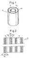
- FIG. 1 One embodiment of a fuel cell section constituting the inventive fuel cell device is shown in Fig. 1.
- the fuel cell section 10 shown in Fig. 1 two vertically arranged cylindrical fuel cells 10a and 10b different in inner diameter from each other are disposed concentric with each other with a space 14 between the two.
- each of the fuel cells 10a and 10b constituting the fuel cell section 10 is formed by laminating a solid-electrolyte layer 12a, an anode layer 12b and a cathode layer 12c concentrically with each other.
- the anode layer 12b is formed on the outer circumference of the solid-electrolyte layer 12a and the cathode layer thereof is formed on the inner circumference of the solid-electrolyte layer 12a.
- the anode layer 12b is formed on the inner circumference of the solid-electrolyte layer 12a and the cathode layer 12c is formed on the outer circumference of the solid-electrolyte layer 12a.
- the anode layer 12b is formed on the outer circumference of the fuel cell 10a, and the anode layer 12b is formed on the inner circumference of the fuel cell 10b. Accordingly, in the fuel cell section 10 formed by inserting the fuel cell 10a having a smaller inner diameter into the fuel cell 10b having a larger inner diameter, a space 14 is obtained in which the anode layer 12b formed on the outer circumference of the fuel cell 10a is located opposite to the anode layer 12b formed on the inner circumference of the fuel cell 10b.
- the solid-electrolyte layers 12a forming the fuel cells 10a and 10b are preferably made of zirconium oxide partially stabilized by a third group element (in the Periodic Table) such as yttrium (Y) or scandium (Sc), or cerium oxide doped with samarium (Sm) or gadolinium (Gd).
- a third group element in the Periodic Table
- Y yttrium
- Sc scandium
- Ce cerium oxide doped with samarium (Sm) or gadolinium (Gd).
- the anode layer 12b is preferably made of a fired material mainly composed of NiO in which Li is contained as a solid solution.
- This fired material is an-electro-conductive ceramic obtained by adding a Li compound, in a range from 1 to 15 mol% converted into Li 2 O equivalent, to NiO and firing the mixture.
- a metal such as rhodium, platinum, ruthenium, palladium, rhenium or iridium or oxide thereof is blended.
- the fuel cell device constituted by the fuel cells 10a and 10b having the anode layers 12b blended with such metal or oxide thereof it is possible to exhibit a higher performance for generating electric power than a fuel cell device constituted by the anode layers 12b blended with no metal such as rhodium or others or oxide thereof.
- the metal such as rhodium, platinum, ruthenium, palladium, rhenium or iridium or oxide thereof is preferably blended in the anode layer 12b in a range from 1 to 50 wt% interms of the metal.
- a contact area of the metal such as rhodium, platinum, ruthenium, palladium, rhenium or iridium or oxide thereof with a mixed fuel gas by blending 50 vol% or less of either one of samaria-doped ceria, scandia-stabilized zirconia and yttria-stabilized zirconia as an accessary constituent for the anode layer 12b.
- the cathode layer 12c is formed of manganese, gallium or cobalt oxide of lanthanum added with a third group element (in the Periodic Table) such as strontium (Sr).
- the anode layer 12b and the cathode layer 12c are porous layers having a porosity of 20% or more, preferably in a range from 30 to 70%, more preferably from 40 to 50%.
- the fuel cell 10a shown in Figs. 1 and 2 is obtained by using a shape-retaining tubular core of the same material as the cathode layer 12c on which are wrapped a solid-electrolyte cell material to be the solid-electrolyte layer 12a and an anode cell material to be the anode layer 12b or coated with pastes of these materials in this order, which layers are then fired at a predetermined temperature.
- the fuel cell 10b having a desired inner diameter is obtained by using a shape-retaining tubular core of the same material as the anode layer 12b on which are wrapped a solid-electrolyte cell material to be the solid-electrolyte layer 12a and a cathode cell material to be the cathode layer 12c or coated with pastes of these materials in this order, which layers are then fired at a predetermined temperature.
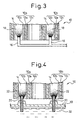
- nozzles 16, 16, ... for supplying gaseous fuel such as butane or propane are provided at a lower end of the space 14 in which the anode layers 12b and 12b are opposite to each other as shown in Fig. 3 in a standing-up state.
- hydrocarbon, hydrogen or various radicals are usable for the generation of electric power by the anode layers 12b, 12b encircling the flames 18, 18, ....
- the fuel cell 10a and 10b having the anode layers 12b formed of the fired material mainly composed of NiO in which Li is contained as a solid solution not only the reducing flame portions of the flames 18, 18, ... but also the oxidizing flame portions are usable for the generation of electric power.
- liquid fuel can also be supplied.
- Fig. 4 is a sectional view of the fuel supply means for supplying liquid fuel such as ethanol provided at a lower end of the space 14 in which the anode layers 12b and 12b are opposite to each other while the fuel cell section 10 is in the standing-up state.
- liquid fuel such as ethanol
- the means for supplying liquid fuel such as ethanol shown in Fig. 4 is constituted by a tank 30 for storing the liquid fuel 32 such as ethanol and supplying members 20, one ends of which are dipped in the liquid fuel 32 in the tank 30 and the other ends are inserted into a lower end of the space 14 in which the anode layers 12b and 12b are located opposite to each other.
- the supplying member 20 may be composed of heat-durable fibers collected to convey the liquid fuel upward due to the capillarity thereof.
- the supplying member 20 may be provided to be movable upward and downward.
- the fuel cells 10a and 10b can be heated to generate the electric power while using heat, hydrocarbon, hydrogen or various radicals generated from the flames 22, 22, ... .
- the fuel cell section 10 shown in Figs. 1 to 4 includes the two fuel cells 10a and 10b.
- the electric power generated from the fuel cells 10a and 10b may be individually taken out.
- the fuel cells 10a and 10b may be preferably connected in parallel to each other by wires 24, 24, ..., or as shown in Fig. 6, the fuel cells 10a and 10b may be preferably connected in series to each other by wires 24, 24, ..., so that the electric power is collectively taken out.
- Figs. 7 and 8 are illustrations of another embodiment of a fuel cell section according to this invention.
- this embodiment there are arranged, vertically, four cylindrical fuel cells 10a, 10b, 10c and 10d different in diameter to each other and are arranged in concentric with each other. Therefore, in this embodiment, two annular spaces 14, i.e., inner and outer annular spaces 14, 14, each having a predetermined gap, are defined between the anode layers 12b, 12b of the adjacent cylindrical fuel cells 10a and 10b, and between the anode layers of the adjacent cylindrical fuel cells 10c and 10d, respectively.
- the fuel cell section 10 shown in Figs. 1 to 8 is formed by disposing the a plurality of cylindrical fuel cells 10a, 10b, ... concentric with each other, it may be possible as shown in Fig. 9 to provide a fuel cell section 40 formed of a plurality of flat-plate type fuel cells.
- Each of the fuel cells 40a, 40b, 40c and 40d has an anode layer 42b on one surface of a solid-electrolyte layer 42a and a cathode layer 42c on the other surface of the solid-electrolyte layer 42a.
- the fuel cells 40a and 40b and the fuel cells 40c and 40d are disposed so that the anode layers 42b and 42b thereof are opposite to each other.
- the fuel cells 40a, 40b, 40c and 40d constituting the fuel cell section 40 shown in Fig. 9 are formed of the same material as the fuel cells 10a and 10b shown in Figs. 1 to 6 and, therefore, a detailed description thereof will be eliminated.
- the fuel cells 40a, 40b, 40c and 40d are obtainable by laminating green sheets of predetermined shapes suitable for the respective layers on a solid-electrolyte layer 42a preliminarily formed by the firing, or coating pastes for the respective layers thereon, and thereafter firing the same again.
- While the electric power generated from the fuel cells 40a, 40b, 40c and 40d may be individually taken out from the respective fuel cells, it may be taken out in a collective manner by connecting the fuel cells 40a, 40b, 40c and 40d in parallel or series to each other.
- the inventive fuel cell device it is possible to effectively use heat of the flame to supply sufficient amount of air to the cathode layer. Therefore, it is possible to generate the electric power by effectively using hydrocarbon, hydrogen or various radicals formed in the flame and oxygen in air on the anode layer while heating the fuel cells by the flames on the anode layer.
- the fuel cell device according to the present invention is applicable to the outdoor use in camping or for emergency use.
- heat generated from the fuel cell device may be used for room heating to save energy.
Landscapes
- Chemical & Material Sciences (AREA)
- Engineering & Computer Science (AREA)
- Chemical Kinetics & Catalysis (AREA)
- Electrochemistry (AREA)
- General Chemical & Material Sciences (AREA)
- Life Sciences & Earth Sciences (AREA)
- Manufacturing & Machinery (AREA)
- Sustainable Development (AREA)
- Sustainable Energy (AREA)
- Materials Engineering (AREA)
- Fuel Cell (AREA)
- Inert Electrodes (AREA)
Abstract
Description
Claims (6)
- A fuel cell device comprising:at least two fuel cells, each comprising a solid-electrolyte layer having first and second surfaces, an anode layer formed on the first surface of the solid-electrolyte layer, and a cathode layer formed on the other surface of the solid-electrolyte layer;said at least two fuel cells being mutually arranged in such a manner that said anode layer of one of said fuel cells faces said anode layer of another, adjacent fuel cell with a predetermined space between them and said space extends from a lower position to an upper position; anda fuel supply unit for supplying fuel into said space at the lower position thereof so that a flame is formed in said space in a direction in which said space extends.
- A fuel cell device as set forth in claim 1, wherein said at least two fuel cells have respective cylindrical shapes, which are concentrically arranged in such a manner that said space defines an annular-shaped space between said anode layers of the two adjacent fuel cells.
- A fuel cell device as set forth in claim 1, wherein said at least two fuel cells have respective flat-shapes, which are arranged in parallel to each other in such a manner that said space defines a flat space having a predetermined width between said anode layers of the adjacent two fuel cells arranged in parallel.
- A fuel cell device as set forth in any preceding claim, wherein said fuel supply unit is a gaseous fuel supply unit.
- A fuel cell device as set forth in any one of claims 1 to 3, wherein said fuel supply unit is a liquid fuel supply unit.
- A fuel cell device as set forth in any preceding claim, wherein said anode layer is made of a fired material mainly composed of NiO in which Li is contained in a solid solution.
Applications Claiming Priority (2)
| Application Number | Priority Date | Filing Date | Title |
|---|---|---|---|
| JP2003104333 | 2003-04-08 | ||
| JP2003104333A JP4319852B2 (en) | 2003-04-08 | 2003-04-08 | Fuel cell |
Publications (2)
| Publication Number | Publication Date |
|---|---|
| EP1467427A2 true EP1467427A2 (en) | 2004-10-13 |
| EP1467427A3 EP1467427A3 (en) | 2005-06-29 |
Family
ID=32866727
Family Applications (1)
| Application Number | Title | Priority Date | Filing Date |
|---|---|---|---|
| EP04252048A Withdrawn EP1467427A3 (en) | 2003-04-08 | 2004-04-06 | Fuel cell device |
Country Status (5)
| Country | Link |
|---|---|
| US (1) | US20040202910A1 (en) |
| EP (1) | EP1467427A3 (en) |
| JP (1) | JP4319852B2 (en) |
| CN (1) | CN100386913C (en) |
| CA (1) | CA2463265A1 (en) |
Cited By (6)
| Publication number | Priority date | Publication date | Assignee | Title |
|---|---|---|---|---|
| EP1507305A3 (en) * | 2003-08-11 | 2006-01-04 | Shinko Electric Industries Co., Ltd. | Solid electrolyte fuel-cell device |
| EP1675202A1 (en) * | 2004-12-21 | 2006-06-28 | Shinko Electric Industries Co., Ltd. | Solid oxide fuel cell with internal combustion chamber |
| EP1675203A1 (en) * | 2004-12-22 | 2006-06-28 | Shinko Electric Industries Co., Ltd. | Solid oxide fuel cell with internal combustion chamber |
| EP1675204A3 (en) * | 2004-12-22 | 2007-05-09 | Shinko Electric Industries Co., Ltd. | Fuel battery |
| EP1837943A1 (en) * | 2006-03-24 | 2007-09-26 | Institute of Nuclear Energy Research Atomic Energy Council, Executive Yuan | Solid oxide fuel cell of multiple tabular electrodes |
| US7674543B2 (en) | 2005-11-08 | 2010-03-09 | Institute Of Nuclear Energy Research Atomic Energy Council | Solid oxide fuel cell of multiple tubular electrodes |
Families Citing this family (6)
| Publication number | Priority date | Publication date | Assignee | Title |
|---|---|---|---|---|
| JP2007042354A (en) * | 2005-08-02 | 2007-02-15 | Paloma Ind Ltd | FUEL CELL POWER GENERATION METHOD, GAS BURNER USED FOR THE METHOD, AND GAS EQUIPMENT HAVING THE GAS BURNER |
| US20070154759A1 (en) * | 2005-11-30 | 2007-07-05 | Shinko Electric Industries Co., Ltd. | Solid oxide fuel cell electric power generation apparatus |
| JP2007157336A (en) * | 2005-11-30 | 2007-06-21 | Shinko Electric Ind Co Ltd | Power generation device using solid oxide fuel cell |
| JP4999436B2 (en) * | 2006-12-01 | 2012-08-15 | 新光電気工業株式会社 | Direct flame fuel cell |
| US8738058B2 (en) * | 2009-04-06 | 2014-05-27 | Qualcomm Incorporated | High-priority communications sessions within a wireless communications system |
| KR101255890B1 (en) | 2010-09-03 | 2013-04-17 | 삼성전기주식회사 | Solid Oxide Fuel Cell |
Family Cites Families (7)
| Publication number | Priority date | Publication date | Assignee | Title |
|---|---|---|---|---|
| US3492162A (en) * | 1965-07-27 | 1970-01-27 | Gen Electric | Fuel cell and method for generating electrical energy by burning a portion of the fuel |
| SE311678B (en) * | 1966-03-25 | 1969-06-23 | Asea Ab | |
| JPH07118327B2 (en) * | 1990-07-07 | 1995-12-18 | 日本碍子株式会社 | Solid oxide fuel cell and porous electrode body used therefor |
| JPH06196176A (en) * | 1992-12-22 | 1994-07-15 | Matsushita Electric Ind Co Ltd | Combustion equipment |
| DE19618220A1 (en) * | 1996-05-07 | 1997-11-13 | Bosch Gmbh Robert | Device for generating heat and for generating electrochemical electricity |
| US6766817B2 (en) * | 2001-07-25 | 2004-07-27 | Tubarc Technologies, Llc | Fluid conduction utilizing a reversible unsaturated siphon with tubarc porosity action |
| US20040237529A1 (en) * | 2002-02-25 | 2004-12-02 | Da Silva Elson Dias | Methods and systems for reversibly exchanging energy between inertial and rotating forces |
-
2003
- 2003-04-08 JP JP2003104333A patent/JP4319852B2/en not_active Expired - Fee Related
-
2004
- 2004-04-05 CA CA002463265A patent/CA2463265A1/en not_active Abandoned
- 2004-04-05 US US10/816,879 patent/US20040202910A1/en not_active Abandoned
- 2004-04-06 EP EP04252048A patent/EP1467427A3/en not_active Withdrawn
- 2004-04-08 CN CNB2004100337100A patent/CN100386913C/en not_active Expired - Fee Related
Cited By (7)
| Publication number | Priority date | Publication date | Assignee | Title |
|---|---|---|---|---|
| EP1507305A3 (en) * | 2003-08-11 | 2006-01-04 | Shinko Electric Industries Co., Ltd. | Solid electrolyte fuel-cell device |
| US7470480B2 (en) | 2003-08-11 | 2008-12-30 | Shinko Electric Industries Co., Ltd. | Solid electrolyte fuel-cell device |
| EP1675202A1 (en) * | 2004-12-21 | 2006-06-28 | Shinko Electric Industries Co., Ltd. | Solid oxide fuel cell with internal combustion chamber |
| EP1675203A1 (en) * | 2004-12-22 | 2006-06-28 | Shinko Electric Industries Co., Ltd. | Solid oxide fuel cell with internal combustion chamber |
| EP1675204A3 (en) * | 2004-12-22 | 2007-05-09 | Shinko Electric Industries Co., Ltd. | Fuel battery |
| US7674543B2 (en) | 2005-11-08 | 2010-03-09 | Institute Of Nuclear Energy Research Atomic Energy Council | Solid oxide fuel cell of multiple tubular electrodes |
| EP1837943A1 (en) * | 2006-03-24 | 2007-09-26 | Institute of Nuclear Energy Research Atomic Energy Council, Executive Yuan | Solid oxide fuel cell of multiple tabular electrodes |
Also Published As
| Publication number | Publication date |
|---|---|
| EP1467427A3 (en) | 2005-06-29 |
| JP2004311249A (en) | 2004-11-04 |
| CA2463265A1 (en) | 2004-10-08 |
| CN100386913C (en) | 2008-05-07 |
| JP4319852B2 (en) | 2009-08-26 |
| CN1536697A (en) | 2004-10-13 |
| US20040202910A1 (en) | 2004-10-14 |
Similar Documents
| Publication | Publication Date | Title |
|---|---|---|
| US7157169B2 (en) | Fuel cell | |
| EP1596457B1 (en) | Solid electrolyte fuel cell configuration | |
| EP1467427A2 (en) | Fuel cell device | |
| JP5882857B2 (en) | Solid oxide fuel cell, cell stack device, and fuel cell module | |
| US20080152983A1 (en) | Solid oxide fuel cell power generator | |
| US8361671B2 (en) | Solid electrolyte fuel-cell device | |
| KR101299935B1 (en) | Uniform gas distribution through channels of sofc | |
| EP1394885B1 (en) | Fuel cell | |
| CA2314907A1 (en) | Fuel cell unit | |
| US6599654B2 (en) | Fuel cell and multi-element stack therefor | |
| US20060134486A1 (en) | Solid oxide fuel cells | |
| EP1675204A2 (en) | Fuel battery | |
| JP2017033653A (en) | Solid oxide type fuel battery stack, solid oxide type fuel battery module and solid oxide type fuel battery system | |
| US20070190381A1 (en) | Solid oxide fuel cell electric power generation apparatus | |
| US20050048352A1 (en) | Fuel-cell device utilizing surface-migration on solid oxide | |
| US20070020494A1 (en) | Solid-oxide fuel-cell power generating apparatus | |
| US20070020495A1 (en) | Power generating apparatus using solid oxide fuel cell | |
| KR101940712B1 (en) | Solid oxide fuel cell and method for manufacturing the same | |
| JP6110524B2 (en) | Solid oxide fuel cell, cell stack device, and fuel cell module | |
| US20070154759A1 (en) | Solid oxide fuel cell electric power generation apparatus | |
| JP2017103251A (en) | Solid oxide fuel cell, cell stack device, and fuel cell module | |
| KR20160068205A (en) | Solid oxide fuel cell and method for manufacturing the same |
Legal Events
| Date | Code | Title | Description |
|---|---|---|---|
| PUAI | Public reference made under article 153(3) epc to a published international application that has entered the european phase |
Free format text: ORIGINAL CODE: 0009012 |
|
| AK | Designated contracting states |
Kind code of ref document: A2 Designated state(s): AT BE BG CH CY CZ DE DK EE ES FI FR GB GR HU IE IT LI LU MC NL PL PT RO SE SI SK TR |
|
| AX | Request for extension of the european patent |
Extension state: AL HR LT LV MK |
|
| PUAL | Search report despatched |
Free format text: ORIGINAL CODE: 0009013 |
|
| AK | Designated contracting states |
Kind code of ref document: A3 Designated state(s): AT BE BG CH CY CZ DE DK EE ES FI FR GB GR HU IE IT LI LU MC NL PL PT RO SE SI SK TR |
|
| AX | Request for extension of the european patent |
Extension state: AL HR LT LV MK |
|
| RIC1 | Information provided on ipc code assigned before grant |
Ipc: 7H 01M 8/06 B Ipc: 7H 01M 8/12 B Ipc: 7H 01M 8/24 B Ipc: 7H 01M 8/04 A |
|
| 17P | Request for examination filed |
Effective date: 20051213 |
|
| AKX | Designation fees paid |
Designated state(s): CH DE FR GB LI |
|
| STAA | Information on the status of an ep patent application or granted ep patent |
Free format text: STATUS: THE APPLICATION IS DEEMED TO BE WITHDRAWN |
|
| 18D | Application deemed to be withdrawn |
Effective date: 20101102 |