EP1467392A2 - Depression responsive switch unit - Google Patents
Depression responsive switch unit Download PDFInfo
- Publication number
- EP1467392A2 EP1467392A2 EP04008389A EP04008389A EP1467392A2 EP 1467392 A2 EP1467392 A2 EP 1467392A2 EP 04008389 A EP04008389 A EP 04008389A EP 04008389 A EP04008389 A EP 04008389A EP 1467392 A2 EP1467392 A2 EP 1467392A2
- Authority
- EP
- European Patent Office
- Prior art keywords
- depression
- knob
- elastic sheet
- switch
- case
- Prior art date
- Legal status (The legal status is an assumption and is not a legal conclusion. Google has not performed a legal analysis and makes no representation as to the accuracy of the status listed.)
- Withdrawn
Links
Images
















Classifications
-
- H—ELECTRICITY
- H01—ELECTRIC ELEMENTS
- H01H—ELECTRIC SWITCHES; RELAYS; SELECTORS; EMERGENCY PROTECTIVE DEVICES
- H01H13/00—Switches having rectilinearly-movable operating part or parts adapted for pushing or pulling in one direction only, e.g. push-button switch
- H01H13/70—Switches having rectilinearly-movable operating part or parts adapted for pushing or pulling in one direction only, e.g. push-button switch having a plurality of operating members associated with different sets of contacts, e.g. keyboard
- H01H13/78—Switches having rectilinearly-movable operating part or parts adapted for pushing or pulling in one direction only, e.g. push-button switch having a plurality of operating members associated with different sets of contacts, e.g. keyboard characterised by the contacts or the contact sites
- H01H13/807—Switches having rectilinearly-movable operating part or parts adapted for pushing or pulling in one direction only, e.g. push-button switch having a plurality of operating members associated with different sets of contacts, e.g. keyboard characterised by the contacts or the contact sites characterised by the spatial arrangement of the contact sites, e.g. superimposed sites
-
- H—ELECTRICITY
- H01—ELECTRIC ELEMENTS
- H01H—ELECTRIC SWITCHES; RELAYS; SELECTORS; EMERGENCY PROTECTIVE DEVICES
- H01H13/00—Switches having rectilinearly-movable operating part or parts adapted for pushing or pulling in one direction only, e.g. push-button switch
- H01H13/70—Switches having rectilinearly-movable operating part or parts adapted for pushing or pulling in one direction only, e.g. push-button switch having a plurality of operating members associated with different sets of contacts, e.g. keyboard
- H01H13/702—Switches having rectilinearly-movable operating part or parts adapted for pushing or pulling in one direction only, e.g. push-button switch having a plurality of operating members associated with different sets of contacts, e.g. keyboard with contacts carried by or formed from layers in a multilayer structure, e.g. membrane switches
-
- H—ELECTRICITY
- H01—ELECTRIC ELEMENTS
- H01H—ELECTRIC SWITCHES; RELAYS; SELECTORS; EMERGENCY PROTECTIVE DEVICES
- H01H25/00—Switches with compound movement of handle or other operating part
- H01H25/04—Operating part movable angularly in more than one plane, e.g. joystick
- H01H25/041—Operating part movable angularly in more than one plane, e.g. joystick having a generally flat operating member depressible at different locations to operate different controls
-
- H—ELECTRICITY
- H01—ELECTRIC ELEMENTS
- H01H—ELECTRIC SWITCHES; RELAYS; SELECTORS; EMERGENCY PROTECTIVE DEVICES
- H01H2221/00—Actuators
- H01H2221/058—Actuators to avoid tilting or skewing of contact area or actuator
-
- H—ELECTRICITY
- H01—ELECTRIC ELEMENTS
- H01H—ELECTRIC SWITCHES; RELAYS; SELECTORS; EMERGENCY PROTECTIVE DEVICES
- H01H2225/00—Switch site location
- H01H2225/002—Switch site location superimposed
-
- H—ELECTRICITY
- H01—ELECTRIC ELEMENTS
- H01H—ELECTRIC SWITCHES; RELAYS; SELECTORS; EMERGENCY PROTECTIVE DEVICES
- H01H2225/00—Switch site location
- H01H2225/018—Consecutive operations
-
- H—ELECTRICITY
- H01—ELECTRIC ELEMENTS
- H01H—ELECTRIC SWITCHES; RELAYS; SELECTORS; EMERGENCY PROTECTIVE DEVICES
- H01H2235/00—Springs
Definitions
- the present invention relates to a depression responsive switch unit which is turned on in response to the depression of a knob.
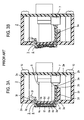
- a conventional depression responsive two-step switch unit which is disclosed in Japanese Laid-Open Patent Application No. 315,682/96 (laid open November 29, 1996) will be briefly described with reference to Figs. 1, 2, 3A and 3B.
- a rectangular case 2 includes a surface plate 2a, in which a rectangular opening 2-1 is formed, and a key top 3 is disposed to substantially block the opening 2-1.
- the key top 3 includes an elongate frame-shaped sidewall 3g, on the inner surface of which a reinforcing plate 3c is fitted and is secured in position by claws 3d.
- a membrane sheet 6 is held in overlapping relationship with the front side of the reinforcing plate 3c, and a surface sheet 3e is disposed on the front side of the membrane sheet 6 and is adhesively bonded to the end face of the sidewall 3g of the key top 3.
- a plurality of depression regions 3p are defined in an array on the surface sheet 3e, and are designated by key identification characters, which are numbers “1", “2", ⁇ , "8” in the example shown. Regions on the membrane sheet 6 which are located opposite to the depression regions 3p are each designated as a membrane switch 6s.
- a pair of flexible films 6a and 6b as may be formed by polyethylene films, are stacked together with a spacer 6c therebetween to define a switch assembly for each depression region 3p.
- fixed contacts 6d and 6e are formed on the film 6a while a movable contact 6f is formed on the film 6b so as to be located opposite to the contacts 6d and 6e, thus completing the membrane switch 6s.
- Rotary shafts 3f project externally from the opposite ends of the sidewall 3g of the key top 3 and are rotatably engaged with bearings 2f which are formed in the internal surface of the surface plate 2a of the case.
- the membrane switch 6s which is located opposite thereto has its movable contact 6f moved into contact with the both fixed contacts 6d and 6e, thus turning the switch on.
- the key top 3 moves angularly as shown in Fig. 3B and a pusher 3a extending form one side of the sidewall 3g of the key top 3 presses against a tact switch 7 which is mounted on the internal surface of a rear plate 2b of the case 2, thus turning it on.
- a two-step switch which is constructed in the manner mentioned above finds its use in an application where a temporary input is selectively made initially and a true input is made after confirmation of the temporary input.
- an on-load is relatively high when an input is to be made to the first step switch, there is a likelihood that the second step switch may be turned on inadvertently.
- a menu is displayed on a display screen, one of items in the menu is selected by a corresponding key, and on the basis of this selection, the display screen displays what item has been selected, and a user confirms this display, and if the display is proper, the user performs a key entry in order for that item to be truly selected.
- a user it is possible for a user to try an entry by gently depressing a suitable key (depression region 3p) without recognizing a key operation surface, which may be the display of switch identifications on the surface sheet 3e in the example of Fig. 1, to know that one color among the menu items which corresponds to the display of the switch identification for the depressed key (depression region 3p) has changed to red or that that item has been selected without requiring the visual recognition of the display of the switch identifications. If the selected item is different from an item which the user desires to select, the user may then depress another depression region 3p gently. On the contrary, if the selected item were the item which the user intended to select, an entry for that item can be accomplished by further depressing the key.
- a suitable key depression region 3p
- a selection from the menu can properly be accomplished without viewing the key operation surface, but while viewing only the display screen.
- an operation of an onboard air conditioner, a control over CD player or DVD player, a selection of a radio channel to be received, a display of TV channel to be received or a display of an automatic road guide can be made while driving an automobile.
- the use of a two-step switch unit is greatly convenient in making a selection or exercising a control without a visual recognition of a key display surface or while performing a different task such as driving an automobile.
- a pressure that is required to make a temporary entry through the first step switch be small in magnitude. It is desirable that the first step switch can be operated with a pressure which is as weak as "tangibly feeling" the key display surface with a fingertip or "slipping" the fingertip along the key display surface.
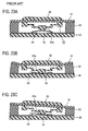
- FIG. 23 An example of a conventional depression responsive single step switch unit will be described below with reference to Fig. 23.
- This switch unit is disclosed in Japanese Patent No. 3,306,311 (issued July 24, 2002).
- a depressing piece 60 is depressed, a flexible sheet 61 becomes flexed, and a frame-shaped cushion member 62 as may be formed of urethane foam and on which the flexible sheet 61 is applied is increasingly squeezed, and a driving piece 63a of a driver 63 which is formed of a synthetic resin material and which is mounted on the internal surface of the flexible sheet 61 comes into contact with a click plate 64.
- a load applied to the click plate 64 exceeds a given value, there occurs a reversal in the central portion of the click plate 64 as shown in Fig. 23B, whereby a membrane switch 6s is depressed to turn the switch on.
- a baseplate 65 is mounted on the surface of the frame-shaped cushion member 62 which is opposite from the flexible sheet 61 with the interposition of a sheet which defines the membrane switch 6s. In other words, the membrane switch 6s and the click plate 64 are secured to the baseplate 6s within an extent defined by the frame-shaped cushion member 62.
- a switch having a lower peak of on-load has a long useful life because the stresses to which the switch is subject in order to provide the clicking sensation and because the stresses to which the switch is subject from a return spring during the reversal are both small.
- the return spring will be subject to correspondingly higher stresses, thus shortening the useful life.
- a depressing piece 72 faces externally through an opening 71b formed in a surface plate 71a of a case 71.
- a rib 72a formed on the peripheral surface of the depressing piece 72 is guided by a guide groove 71d of a tubular guide 71c which is integrally formed inside the case 71, thus moving toward a rear plate 71e of the case 71 in a direction perpendicular thereto.
- an actuator 73f of a tact switch 73 which is mounted centrally on the internal surface of the rear plate 71e is driven into a switch case 73b by a projection 72c which is formed centrally on the internal surface of a top plate of the depressing piece 72, whereupon an internal spring is reversed to turn the tact switch 73 on.
- the depressing piece 72 is released from the depression, the original configuration is restored due to the resilient restoring force of the spring within the tact switch 73, and the depressing piece 72 is returned to its original position.
- the rear plate 71e of the case 71 is detachable, and a screw 74 is passed through a bore 71 f formed in the rear plate 71e and is screwed into a bore 71g formed in the end face of a sidewall 71i of the case 71, whereby the rear plate 71e is secured to the sidewall 71i.
- the depressing piece 71 moves in a direction perpendicular to the rear plate 71e if the depression is directed obliquely and if the depression is applied to one end of the depressing piece 71.
- a friction acting between the rib 72 and the guide groove 71d increases, and it becomes necessary to increase the depressing force.
- a switch operation may be prohibited for a depressing force of an equal magnitude.
- a problem relating to the sensation of operation remains in a similar manner as in the arrangement of Fig. 23.
- the arrangement may become larger in size because of a guide construction for the depressing piece 72.
- the present invention relates to a two step depression responsive switch unit in which a second step switch is interposed between a movable reinforcing plate and a case surface plate within a case and in which a plurality of first step switches are disposed on a case front side of the reinforcing plate.
- a knob which depresses the second step switch.
- the knob includes depressing pieces, each corresponding to the first step switch and formed on an elastic sheet which is extremely pliable as formed by a thermoplasitc elastomer or silicone rubber.
- Each depressing piece has a depressed surface and also has a small projection which projects in the opposite direction from the depressed surface so as to move close to or into contact with a corresponding one of the first step switches.
- Each depressing piece is located in an opening which is formed in a key operation base so as to receive a depressing piece.
- Each depressed surface is located outside the surface of the key operation base, and the reinforcing plate, the elastic sheet and the key operation base are held within the case so as to be simultaneously movable toward the rear plate of the case, and the marginal portion of the elastic sheet is secured to either one of the case, the key operation base and the reinforcing plate.
- the elastic sheet when one of the depressing pieces is selected to be depressed gently, the elastic sheet is deformed (flexed) to turn one of the first step switches on. If the depression is further continued, the reinforcing plate moves to turn the second step switch on.
- the on-load of the first step switch principally comprises a reaction from only the elastic sheet which is extremely pliable. Since the elastic sheet is constructed with a thermoplastic elastomer or a silicone rubber, its reaction is considerably smaller as compared with the reaction of a single surface sheet which comprises polyethylene sheet or polycarbonate sheet used in the prior art.
- an operation of the first step switch can be made without any particular attention to a distinction between the operation of the first step switch and the operation for the second step switch, or without any need to be conscious not to operate the second step switch when the first step switch is to be operated.
- the first step switch can be turned on by tangibly feeling the key display surface with a finger or slipping the finger along the key display surface, for example.
- a depression responsive switch unit in which a depression of a knob turns a switch on.
- the knob is disposed within an opening formed in a surface plate of a rigid body, and a switch is disposed between the knob and the case rear plate.
- the knob is retained in the case by a resilient member such that it is readily displaceable in the direction of a normal depression, but is hardly displaceable in a direction perpendicular to the direction of the normal depression.
- the case comprises a rigid body, and even though there is no guide means for the knob, the retaining function of the resilient member is such that if the direction of depression deviates from the normal direction, and if one end of the knob is depressed, the switch can be reliably turned on.
- a return spring has an increased useful life and could be constructed in a compact manner.
- a first mode of carrying out the present invention is a depression responsive two-step switch unit in which the marginal portion of the elastic sheet is carried by a case.
- a second step switch 36 is disposed on a rear plate 39h within a case 39 and a reinforcing plate 35 is disposed on top of the second step switch 36.
- a plurality of first step switches 34s are disposed on the reinforcing plate 35.
- a key operation base 33 is disposed on the side of the reinforcing plate 35 which is located toward the first step switch 34s. At locations corresponding to each of the first step switches 34s, the key operation base 33 is formed with depression openings 33a extending therethrough.
- a knob 32 is disposed on the front side of the key operation base 33.
- the knob 32 includes depressing pieces 32a which are formed on an extremely pliable elastic sheet 32c which comprises a thermoplastic elastomer or a silicone rubber at locations corresponding to one of the first step switches 34s, and each depressing piece 32a has a depressed surface 32a2 which is located forwardly of the elastic sheet 32c.
- Each depressing piece 32a is at least partly located within the depression opening 33a formed in the key operation base 33 and includes a small projection 32b which projects from the surface opposite from the depressed surface 32a2.
- Each small projection 32b is located close to or is in contact with a corresponding one of the first step switches 34s.
- the marginal portion 32d of the elastic sheet 32c is retained by the case 39.
- the case 39 comprises a rear plate 39h, sidewalls 39a and 39d which are integral therewith, and a cover 31 which abuts against and which is secured to the end faces of the sidewalls 39a and 39d to serve as a front plate.
- the marginal portion 32d of the elastic sheet 32c is held sandwiched between the cover (front plate) 31 and the sidewall 39a to be retained by the case 39.
- the knob 32 and the key operation base 33 are secured together as are the first step switches 34s and the reinforcing plate 35, whereby they are simultaneously reciprocable with respect to the rear plate 39h.
- the second step switch 36 is constructed to be automatically reset when it is released from the depression or assumes a turn-off condition while desirably providing a clicking sensation or a sensation that a switch operation has been made.
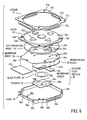
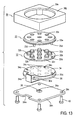
- FIG. 4 A cross section of the first embodiment taken along the line IV-IV shown in Fig. 5 is shown in Fig. 4, a plan view is shown in Fig. 5, and the exploded perspective view is shown in Fig. 6.
- a cover (front plate) 31 comprises a metal sheet which is machined as required, and includes a square portion 31a in which a circular opening 31b is formed. Each side of the square portion 31a has a U-shaped detent 31c having short limbs which is bent in a direction perpendicular to the square portion 31a to extend toward the rear plate 39h.
- a knob 32 comprises a square-shaped elastic sheet 32c, which extends outside the opening 31b formed in the cover 31 except for its marginal portion 32d to define a circular top surface on which five depressing pieces 32a are formed as projections in this example.
- One of the depressing pieces 32a which is located centrally has a circular configuration, while the depressing pieces 32a which are located laterally on the opposite sides of the central depressing piece 32a are triangular in configuration.
- the internal surface of each depressing piece 32a projects beyond the elastic sheet 32c toward the rear plate 39h as shown in Fig. 4, and a small projection 32b is formed centrally on the end face of the projection.
- the depressing piece 32a, the small projection 32b and the elastic sheet 32c are integrally molded with a thermoplastic elastomer, and thus is constructed with an extremely pliable material.
- the key operation base 33 is molded from a hard resin such as ABS resin or polycarbonate and is in the form of a disc which corresponds to the circular top surface of the knob 32.
- the key operation base 33 is formed with depression openings 33a which extend therethrough at locations corresponding to each depressing piece 32a of the knob 32 and which are larger than the depressing piece 32a.
- the centrally disposed depression opening 33a is circular in the similar manner as the depressing piece 32a which corresponds thereto while the remaining depression openings 33a are triangular in configuration. While the key operation base 33 and the knob 32 are shown separately in Fig. 6, in the present example, they are integrally molded, and the elastic sheet 32c is secured to the key operation base 33 without any slack therebetween.
- the first step switch 34s uses a membrane sheet 34 which is constructed in the similar manner as the membrane sheet 6 of the prior art described above in connection with Figs. 1 to 3. While not specifically shown in Figs. 4 to 7, the five membrane switches acting as first step switches 34s are formed, each constructed in the similar manner as the membrane switch 6s shown in Fig. 3A and having fixed contacts 6d and 6e and the movable contact 6f. In Fig. 4, such first step switches (membrane switches) 34s are indicated by blank areas (the same is true for a corresponding membrane switch). A tail 34a which is used to take out the lead wire for each of the fist step switches 34s is connected to part of the peripheral edge of the membrane sheet 34.
- a reinforcing plate 35 comprises a stainless steel sheet, for example, and has substantially similar configuration as the membrane sheet 34.
- the second step switch 36 shown in this example comprises a switch body 36s which is constructed in the similar manner as the membrane switch 36s shown in Fig. 3, for example, a click plate 37 and a pusher 38.
- the membrane sheet 40 on which the membrane switch 36s acting as a switch body is constructed is shown in Fig. 6 as being separate from the membrane sheets 34, but they are integrally formed through a connector 40a as shown in Fig. 4, and the connector 40a is folded to place the membrane sheets 34 and 40 on the opposite sides of the reinforcing plate 35.
- the membrane sheet 36s acting as the switch body is also shown as a blank area in Fig. 4 (the same applies for a similar switch).
- an arrangement is made to provide a clicking sensation from a switch operation of the second step switch 36 in a manner mentioned previously, and the click plate 37 is disposed in the region of the membrane switch (switch body) 36s of the membrane sheet 40 on the opposite side of the reinforcing plate 35.
- the click plate 37 comprises a dish-shaped springy metal sheet.
- a pusher 38 is interposed between the click plate 37 and the rear plate 39h so that a restoring force acts automatically when the second step switch 36 is released from the depression.
- the pusher 38 may be formed of rubber, for example, and has a square-shaped flat plate 38a which is centrally formed with a dome 38b which projects toward the rear plate 39h.
- a projection 38c is formed centrally on the internal surface of the dome 38b so as to project toward the click plate 37.
- the case 39 is formed of a hard resin such as ABS resin or polycarbonate and is open toward the front, and is in the form of a shallow square, with each comer being rounded.
- the sidewall 39a which forms one side of the square is somewhat extended externally, and a notch 39b is formed in its end face which is disposed toward the front side. This illustrates an arrangement to allow the tail 34a to be guided externally.
- a pair of small detent tabs 39c are formed on the external surface of the sidewall 39a while the external surface of the sidewalls 39d, which form the remaining three sides of the square, is formed with a detent projection 39e of a substantial length which extends along the respective side.
- a boss 39f is fixedly mounted on the rear plate 39h at a location close to the internal surface of each rounded comer of the case 39.
- the marginal portion 32d of the knob 32 and the top plate 31 a of the cover 31 are formed with openings 32f and 31e, respectively, through which the bosses 39f can be passed.
- a boss 39g is formed centrally on the notch 39b of the case 39 on its front side, and an opening 34b is formed in an end of the membrane sheet 34 which is located toward the tail 34a for passing the boss 39g. It is to be noted that openings 31f, which are formed radially outward of the four openings 31 e in the cover 31 are used for purpose of mounting the two-step switch unit.
- a pair of bosses are formed on the key operation base 33 on the side which faces the rear plate 39h in this example, even though such bosses are hidden from sight in Fig. 6, and the membrane sheet 34 and the reinforcing plate 35 are formed with a pair of openings 34c and 35a, respectively, for passing these bosses.
- the flat plate 38a of the pusher 38 is formed with a pair of bosses 38d, and openings which pass these bosses 38 d are formed in the reinforcing plate 35, the membrane sheet 34 and the key operation base 33.
- Numerals 34d and 33b shown in Fig. 6 shows such openings. It should be noted that the openings formed in the reinforcing plate 35 for passing the bosses 38d are hidden from sight.
- the knob assembly is assembled into the case 39.
- This assembling operation takes place by passing the bosses 39f on the case 39 through the four openings 32f formed in the marginal portion 32d of the knob 32 and passing the boss 39g on the case 39 through the opening 34b formed in the membrane sheet 34. In this manner, the knob assembly is positioned and received within the case 39.
- Fig. 7 shows this condition.
- cover 31 is attached to complete the two-step switch unit.
- the cover 31 is attached by engaging four detents 31c with the detent projections 39c and 39e of the case 39.
- Fig. 8 shows, to an enlarged scale, one location where the marginal portion 32d of the knob 32 and the square portion 31a of the cover 31 are positioned by the bosses 39f on the case 39.
- the cover 31 is positioned by passing the opening 31e thereof over the boss 39f, and the periphery of the knob 32 or the marginal portion 32d of the elastic sheet 32c is held sandwiched between the case 39 and the surface plate or the cover 31 to be retained by the case 39.
- a ring-shaped rib 32g is formed around the opening 32f in the periphery of the knob 32 (or the marginal portion of the elastic sheet) 32d on the side which faces the cover 31, and the square portion 31a of the cover 31 abuts against the marginal portion 32d of the knob 32 only at this ring-shaped rib 32g while a small clearance is maintained with respect to the marginal portion 32d in the remainder.
- the two-step switch unit which is assembled in the manner mentioned above has a construction as shown in Fig. 4 where the pusher 38 is located centrally on the internal surface of the rear plate 39h of the case 39, and the click plate 37, the reinforcing plate 35 which carries membrane sheets 34 and 36 on the opposite sides and the key operation base 33 which is integral with the knob 32 are sequentially mounted thereon.
- the knob 32 or the elastic sheet 32c thereof is disposed on the front side of the key operation base 33 and its marginal portion 32d is supported by the case 39, substantially blocking the opening in the case 39 by the knob 32. In this example, it is secured to the case 39 at a plurality of locations (which are four locations as shown), and other non-anchored portions remain to be free ends.
- the dome 38b of the depressed pusher 38 is squeezed to deform in a manner shown in Fig. 9B, whereby the projection 38c of the pusher 38 presses against the click plate 37.
- the click plate 37 which is pressed in this manner has its central portion reversed in position relative to the peripheral surface of the click plate 37 (hereafter such phenomenon will be simply referred to as a reversal) with a click sensation, thus pressing against the membrane switch 36s which serves as the switch body of the second step switch.
- the contacts (not shown) which are located opposite thereto contact each other to turn the second step switch 36 on.
- the membrane switch 34s which serves as the first step switch is disposed within the switch unit, and accordingly, contacts can be formed on a very thin film, for example, a polyethylene film by a printed circuit technology, allowing the reaction thereof to be minimized.
- the first step switch is turned on by a flexure of only the elastic sheet 32c which comprises a pliable thermoplastic elastomer, the on-load of the first step switch can be minimized.
- the key operation surface is constructed by the key operation base 33 which retains the knob 32, and accordingly, the first step switch can be turned on with a contact of the finger with the depressing piece which is on the order of tangibly feeling the key operation surface with the finger.
- the profile of the knob 32 is maintained by the key operation base 33 without any likelihood of being damaged upon contact with an external member while maintaining the key operation surface.
- the switch bodies of the first and the second step switch are both formed by the membrane sheets 34 and 40, respectively, in the present example, allowing a thin and compact construction while reducing the number of steps of assembly to permit the switch unit to be constructed inexpensively.
- the peripheral portion of the elastic sheet 32c or the marginal portion 32d of the knob 32 is not secured to the case 39 along the full perimeter thereof, but is secured by being positioned at a plurality of points which are four points representing the bosses 39f of the case 39 in this example, whereby a construction is achieved which allows an elastic deformation of the marginal portion 32d to occur readily in the direction of depression while making an elastic deformation in a direction perpendicular to the direction of depression or in a direction parallel to the rear plate 39h hardly occurring.
- the knob 32, the key operation base 33 and the reinforcing plate 35 are readily displaceable in the direction of a normal depression, but are hardly displaceable in a direction perpendicular to the direction of a normal depression.
- an adequate degree of tension occurs in the marginal portion 32d as a result of securing at a plurality of points which are four points in the present example, and if another depressing piece 32a is depressed, or if the knob 32 is edgewise depressed, a rotation of the key operation base 33 about the point of contact between the pusher 38 and the rear plate 39h is unlikely to occur.
- the second step switch can be depressed under a condition that the key operation base 33 assumes a small inclination, affording a good touch and an evenly stroking sensation at this point.
- the key operation surface is defined by the knob 32 of an elastic material which comprises a thermoplastic elastomer, additional effects are obtained that it is comfortable to touch and there is a high grade leather-like appearance.
- a sidewall 39a is molded integrally with a knob 32 as shown in Fig. 10, and the marginal portion 32d of the elastic sheet 32c (knob 32) is secured to the end face of the sidewall 39a along the full perimeter as by an integral molding.
- a redundant portion 32h which is U-shaped in section is formed in the marginal portion 32d of the elastic sheet 32c (knob 32) to extend along the inner periphery of the sidewall 39a. This facilitates an elastic deformation of the marginal portion 32d in a direction toward the rear plate and also makes an elastic deformation in a direction parallel to the rear plate more difficult to occur.
- the knob 32, the key operation base 33 and the reinforcing plate 35 are readily displaceable in the direction of a normal depression and are hardly displaceable in a direction perpendicular to the direction of a normal depression. Accordingly, if the knob 32 is edgewise depressed, there occurs no inclination of the knob 32 (the key operating base 33 and the reinforcing plate 35), allowing the second step switch to be operated with a good touch and an evenly stroking sensation.
- the rear plate 39h of the case 39 is formed by a metal sheet in order to reduce the thickness. Securing the marginal portion 32d of the elastic sheet 32 to the case 39 over the full perimeter may take place in the example shown in Figs. 4 to 8 by omitting the ring-shaped rib 32g shown in Fig. 8 and holding the marginal portion 32d sandwiched between the case 39 and the cover 31 over the full perimeter.
- Fig. 10 illustrates that the depressing piece 32a and the small projection 32b of the knob 32 are integrally constructed with a resin material.
- the elastic sheet 32c is formed with a passing opening 32i in a manner corresponding to each depressing piece 32a, and each depressing piece 32a is formed by a hard resin such as ABS resin or polycarbonate, with a flange 32a1 integrally formed with the depressing piece 32a toward a depressed surface 32a2 and each depressing piece 32a is passed through the corresponding passing opening 32i and the flange 32a1 is brought into abutment against the elastic sheet 32c around the edge of the passing opening 32i.
- a hard resin such as ABS resin or polycarbonate
- a surface opposite from the surface against which the flange 32a1 around the edge of the passing opening 32i abuts is integrally molded with a ring-shaped rib 32c1.
- the elastic sheet 32c which comprises a thermoplastic elastomer, and the depressing piece 32a and the small projection 32b which comprise a hard resin are integrally molded to be secured together.
- the pusher 38 shown in Fig. 4 is omitted, and a projection 39i is integrally formed at the center of the internal surface of the rear plate 39h, with the projecting end face of the projection abutting against the central portion of the convex side of the click plate 37. It will be seen that in this instance also, as one of the depressing pieces 32a is depressed, the click plate 37 is pressed by the projection 39i to reverse, whereby the switch body 36s of the second step switch is turned on.
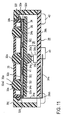
- the second mode of carrying out the present invention is distinct from the first mode of carrying out the invention in that a key operation base 33 is disposed on the front side of an elastic sheet 32c and that the elastic sheet 32c is retained not by the case, but by the key operation base 33 and a reinforcing plate 35, as indicated in Fig. 11, for example, which illustrates a cross section corresponding to Fig. 4.
- the key operation base 33 is formed with a depression opening 33c in a manner corresponding to each depressing piece 32a, and the depressing piece 32a faces the front side from within the case 39 through the respective depression opening 33c.
- a depressed surface 32a2 which is configured to be similar to a part of a spherical surface projects externally from the surface of the key operation base 33.
- the key operation surface is formed by the surface of the key operation base 33 and the depressed surface 32a2 which substantially blocks the depression opening 33c.
- An operator of the two-step switch unit touches the key operation surface with a finger of his hand to operate it for depression. It is not the key operation base 33, but the elastic sheet 32c that contacts the reinforcing plate 35 or the membrane sheet 34.
- the second mode of carrying out the invention may be fundamentally same as in the first mode of carrying out the invention.
- a specific example of the second mode of carrying out the invention will now be described as a third embodiment.
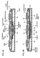
- the third embodiment is shown in Figs. 11 to 16.
- a case 39 is formed with a surface plate 39j in an integral manner with its sidewall, and a large circular opening 39k is formed in the surface plate 39j.
- a key operation base 33 is disposed to substantially block the opening 39k, and the key operation base 33 is formed with a depression opening 33c in a manner corresponding to each depressing piece 32a.
- the depressing piece 32a and the small projection 32b are integrally molded with a hard resin, and this is adhesively secured to or integrally molded with the elastic sheet 32c which comprises a thermoplastic elastomer 32.
- Each depressing piece 32a is disposed in the depression opening 33c in the key operation base 33 to face the exterior. Only a depressed surface 32a2, which forms a part of spherical surface, is slightly exposed from the surface of the key operation base 33 to permit a finger to contact and to slip along the key operation surface so that the existence of the depression piece 32a can be confirmed by tactile impression.
- the elastic sheet 32c is located on the reinforcing plate 35 through the membrane sheet 34 interposed in this instance, and has the small projection 32b as the only portion where it contacts a first step switch, which is a membrane switch 34s within a membrane sheet 34 in this example.
- an air gap formation 32j is formed as a projection on the side of the elastic sheet 32c which is disposed toward the reinforcing plate 35 in a manner corresponding to each adjacent small projection 32b or to the center position between adjacent membrane switches 34s, thus producing an air gap 41 between the elastic sheet 32c and the first step switch (membrane switch) 34s.
- the air gap formation 32j is located at a midpoint between adjacent depressing pieces 32a as viewed in the direction in which the depressing pieces 32a are arrayed.
- the marginal portion 32d of the elastic sheet 32c has an increased thickness and defines a ring-shaped air gap formation which is centered about the centrally located depressing piece 32a.
- the reinforcing plate 35 comprises a molding of a hard resin such as ABS resin or polycarbonate.
- the key operation base 33 is integrally formed with a plurality of bosses 33d as projections on the rear side thereof, and these bosses 33d are sequentially passed through openings 32k formed in the elastic sheet 32c, openings 34c formed in the membrane switches 34s and openings 35a formed in the reinforcing plate 35 in a manner shown in Fig. 15, and their projecting ends are caulked by heat.
- a spacing between the air gap formation on the marginal portion 32d of the elastic sheet 32c and the closest small projection 32b is substantially equal to a spacing between that smaller projection 32b and the air gap formation 32j which is located on the other side from the marginal portion 32d and which is closest thereto.
- a tact switch is used for the second step switch 36.
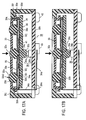
- the tact switch 36 includes an internal resilient member which is reversed in configuration when an actuator 36a is depressed into a switch case 36b by an external force to assume a switch-on condition. The reversal of the resilient member provides a tactile impression (clicking sensation) of a switch operation. When the actuator 36a is released from the external force, the resilient restoring force restores the configuration of the resilient member, thus resuming a switch-off position.
- the tact switch 36 is disclosed, for example, in Japanese Utility Model Registration No. 2,557,784 (issued December 17, 1997).
- the tact switch 36 is secured centrally on the internal surface of the case rear plate 39h, for example, at a predetermined position which is previously marked when the rear plate 39h is formed. As shown in Figs. 11, 15 and 16, the projecting end face of the actuator 36a of the tact switch 36 is abutted by the reinforcing plate 35, which is an integrally formed projection 35b in the present example.
- the resilient restoring force of the resilient member contained in the tact switch 36 acts through the actuator 36a to push back the reinforcing plate 35 toward the surface plate 39j of the case 39 until a flange 33e disposed around the outer periphery of the key operation base 33 abuts against the internal surface of the surface plate 39j.
- the peripheral edge of the disk-shaped key operation base 33 is folded toward the rear side to extend through a small distance, and the flange 33e is integrally formed around the outer periphery of such extension 33f.
- the case 39 is integrally molded with the sidewall of the surface plate 39j, as mentioned previously, allowing the rear plate 39h to be detachable. As shown in Figs 11, 13 and 14, a notch 39m is formed in one side of the rear plate 39h, allowing the membrane sheet tail 34a to be led out.
- the rear plate 39h is brought into abutment against the end face of the sidewall of the case 39 as illustrated in Fig. 11, screws 42 are inserted into openings 39n formed in the rear plate 39h as shown in Figs. 13, 14 and 16, and when the screws 42 are clamped into bores 39p which are formed in the case sidewall, the rear plate 39h is unified with the case.
- a printed circuit board is used for the rear plate 39h.
- a position marker (not shown) which is applied when forming the printed circuit may be utilized when mounting the tact switch 36 with a face bond.
- the tail 34a of the membrane sheet is taken out through the notch 39m and is connected to a connector 43 which is mounted on the outer surface of the rear plate 39h. While the connector 43 has not been shown in the first and the second embodiment, it is a general practice that the tail 34a of the membrane sheet is connected to a connector which is mounted on the outer surface of the case 39, as illustrated in Fig. 11.
- the reinforcing plate 35 moves toward the rear plate 39h against the reaction from the actuator 36a of the tact switch 36, as shown in Fig. 17B, whereby the actuator 36a is driven into the switch case 36b to turn the second step switch 36 on with a clicking sensation.
- the resilient restoring force of the resilient member within the tact switch 36 causes the reinforcing plate 35 to move toward the surface plate 39j, turning the second step switch 36 off, and the membrane switch 34s or the first step switch which has been turned on is turned off again by the restoring force of the elastic sheet 32c.
- the marginal portion 32d of the elastic sheet may be carried by the reinforcing plate 35 as by being adhesively bonded thereto, for example.
- the elastic sheet itself represents the surface of the case or the key operation surface, and the marginal portion of the elastic sheet is retained by the case and the key operation base.
- a knob 32 faces the exterior through an opening 39k in a surface plate 39j
- a key operation base 33 is disposed on the rear side of the knob
- a marginal portion 32d of the elastic sheet 32c is retained by a marginal portion of the key operation base 33.
- Disposed on the rear side of the key operation base 33 is a reinforcing plate 35 on which a first step switch 34s is disposed, and a second step switch means 36 is interposed between the reinforcing plate 35 and a rear plate 39h.
- the knob 32 and the key operation base 33 are interchanged in position.
- a fourth embodiment is shown in Fig. 18.
- a key operation base 33 which is configured in substantially the same manner as the key operation base 33 used in the third embodiment is employed, and a knob 32 is disposed in abutment against the front surface of the key operation base 33.
- the knob 32 which is shown in this example has a depressing piece 32a and a small projection 32b which are integrally molded from a hard resin in the similar manner as the knob shown in Fig. 10.
- Each depressing piece 32a is passed through a passing opening 32i formed in an elastic sheet 32c which comprises a thermoplastic elastomer, and a flange 32a1 which is formed around the periphery of the surface of the depressing piece 32a is adhesively bonded to the elastic sheet 32c.
- a depressed surface 32a2 inclusive of the flange 32a1 is in the form of part of a spherical surface.
- Each depressing piece 32a is passed through a depression opening 33c in the key operation base 33, and the elastic sheet 32c, while being in abutment against the front side of the key operation base 33 without any slack, extends along the outer peripheral surface of an extension 33f of the key operation base 33, and further extends along the front side of the flange 33e in its marginal portion 32f, which is in turn retained by the marginal portion of the key operation base 33 or the flange 33e in the present example.
- the knob 32 may be integrally molded with respect to the molded key operation base 33.
- the marginal portion 32f may be adhesively secured to the flange 33e.
- Each depressing piece 32a is passed through the depression opening 33c in the key operation base 33.
- the depression opening 33c is a concentric circle centered about the depressing piece 32a, and a spacing between an inner peripheral surface of the depression opening 33c and the peripheral surface of the depressing piece 32a is chosen to be a certain size so that a region of the elastic sheet 32c which is disposed therebetween can readily be flexed if the depression applied to the depressing piece 32a is very weak, and assumes substantially same value for the spacing.
- Each small projection 32b for each depressing piece 32a is in contact with or lies close to the first step switch, which is the membrane switch 34s in the present example, in the same manner as in the described embodiments.
- the fourth embodiment is distinct from the second embodiment principally in the manner of retaining the elastic sheet 32c. It should be understood that the unification of the key operation base 33 and the reinforcing plate 35 takes place in the similar manner as in the third embodiment.
- the membrane switch 36s is used for the second step switch means 36, and this is mounted on the internal surface of the rear plate 39h.
- the membrane switch 34s which serves as the first step switch is extended to form the membrane sheet 40 inclusive of the second step switch 36s, in the similar manner as in the first embodiment, but in the fourth embodiment, the connector 40a is not directly folded on the rear side of the reinforcing plate 35, but is folded on the internal surface of the rear plate 30h and is extended along the internal surface.
- the membrane switch 36s disposed within the extended membrane sheet 40 is positioned so as to be opposite to the center of the reinforcing plate 35.
- a click plate 37 is interposed between this portion for the membrane switch 36s and a projection 35b on the reinforcing plate 35. The click plate 37 is in contact with the projecting end face of the projection 35b at the center of the convex side thereof.
- the membrane switch 34s which serves as a corresponding first step switch can be turned on with a very weak force as in the second embodiment.
- the knob 32, the key operation base 33 and the reinforcing plate 35 move toward the rear plate 39h in an integral manner, whereby the projection 35b causes an elastic deformation of the click plate 37, the reversal of which turns the membrane switch 36s which serves as the second step switch on.
- the resilient restoring force of the click plate 37 urges the reinforcing plate 35 toward the surface plate 39j, thus turning the membrane switch 36s off and also turning the membrane switch 34s off.
- a clearance between the peripheral surface of the depressing piece 32a and the inner peripheral surface of the depression opening 33c be chosen to be narrow in order to prevent the ingress of dust, and in consideration of the maneuverability when moving the finger to select a depressing piece and a good appearance.
- the first step switch 34s it is necessary that the depressing piece 32a is displaced without interference with the depression opening 33c if the depressing piece is depressed with a very weak force.
- a reduction in the clearance between the peripheral surface of the depressing piece 32a and the inner peripheral surface of the depressing opening 33c is limited in view of the dimensional accuracy and the cost required.
- the spacing between the peripheral surface of the depressing piece 32a and the inner peripheral surface of the depression opening 33c becomes relatively large because of the necessity to make the on-load of the first step switch 34s as small as possible, and accordingly, it is possible to turn the first step switch 34s on reliably in response to a weak depression force without causing a problem of interference or contacting each other therebetween.
- the key operation surface is covered by the knobs 32 without leaving any clearance, thus precluding the likelihood of the ingress of dust and providing a good touch when selecting the depressing piece 32a by tangibly feeling it with a finger and also providing a good appearance.
- the marginal portion 32d of the elastic sheet 32c may be molded on or adhesively secured to the extension 33f of the key operation base 33.
- the depressing piece 32a and the small projection 32b of the knob 32 may be formed with a hard resin in the similar manner as the knob 32 shown in Fig. 10, while the remainder may be formed of a thermoplastic elastomer.
- a portion 32a3 of the depressing piece 32a which projects from the surface of the elastic sheet 32c may be formed with a hard resin while a remainder thereof 32a4 and the small projection 32b may be formed of a thermoplastic elastomer in an integral manner with the elastic sheet 32c.
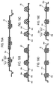
- the knob 32 may be entirely formed of a thermoplastic elastomer in the similar manner as the knob 32 shown in Fig. 4, or may be constructed in the manner shown in Fig. 19A.
- the depressing piece 32a, the small projection 32b, the elastic sheet 32c and the air gap formation 32j of the knob 32 may be entirely formed by an integral molding from a thermoplastic elastomer, as shown in Fig. 19B.
- the small projection 32b, the elastic sheet 32c and the air gap formation 32j may be formed by an integral molding from a thermoplastic elastomer while the depressing piece 32a may be molded from a hard resin and unified with the former by adhesion or by a molding operation, as shown in Fig. 19C.
- parts of the knob 32 may be entirely formed of a thermoplastic elastomer as shown in Fig. 19D.
- the elastic sheet 32c and the portion 32a3 which is exposed externally may be formed of a thermoplastic elastomer while the remainder 32a4 of the depressing piece 32a and the small projection 32b may be integrally formed with a hard resin, as shown in Fig. 19E.
- thermoplastic elastomer used in the knob 32 may be replaced by silicone rubber. It is also possible to form only the small projection 32b with a separate resin material.
- the membrane switch which serves as the first step switch 34s need not be limited to the three contact construction including a pair of fixed contacts and one movable contact as shown in Fig. 3A, but may be constructed by one fixed contact 6d and one movable contact 6f disposed opposite to each other as shown in section in Fig. 20A, for example.
- lead wires for externally connecting the contacts 6a and 6b may be formed on the flexible film 6a on which the fixed contacts are disposed, but in the construction shown in Fig. 20A, it is necessary to form lead wires for external connection of both the fixed contact 6b and the movable contact 6f on the flexible films 6a and 6b, respectively.
- a reinforcing plate 35 is formed by a printed circuit board and the fixed contacts 6d and 6e and their lead wires (not shown) may be printed on the front surface while a flexible film 46 such as a polyethylene film or the like is applied on top of the reinforcing plate 35 with spacers 45a and 45b interposed, and a movable contact 6f is printed on the flexible film 46 so as to be located opposite to the fixed contacts 6d and 6e.
- This flexible film 46 is depressed by the small projection 32b (not shown in Fig.
- a small projection 32b which comprises a conductive rubber or a metal material may be applied as an insert molding to the center of the surface of the depressing piece 32a which is opposite from a depressed surface 32a2, and the small projection 32b may have a planar projecting end face which serves as a movable contact while a pair of fixed contacts 6e and 6d and their associated lead wires may be printed on the reinforcing plate 35 as shown in Fig. 20B so that the fixed contacts 6d and 6e are located opposite to the small projection 32b acting as a movable contact, thus defining a first step switch 34s.
- the small projection 32b may be constructed to have a flat projecting end face, to which a conductive painting or a conductive paste may be applied and hardened to form a movable contact 32b1 which comprises a conductive layer, as shown in Fig. 20D.
- first step switch 34s is shown alone in Figs. 20C and 20D, it should be understood that such first step switch 34s is provided for each depressing piece 32a. While an application to the third embodiment has been illustrated, it may also be applied as each first step switch 34s in the first, the second and the fourth embodiment.
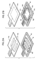
- each first step switch 34s in the first to the fourth embodiment may comprise a switch similar to a so-called touch panel which can be used as coordinate entry means, information entry means or menu selection means or the like.
- flexible films 47a and 47b as may be formed by polyethylene films are closely spaced by a spacer 48 and fixed relative to each other, and a plurality of strip-like electrodes 49a and 49b are formed so as to be parallel to each other on the opposing internal surfaces of the flexible films 47a and 47b.
- the electrodes 49a and 49b are orthogonal to each other.
- a small projection 32b of each depressing piece 32a is disposed in contact with the flexible film 47a at each point of intersection.
- electrodes 49a and 49b at a corresponding point of intersection contact each other to achieve a switch-on condition, and when the depression is released, the electrodes 49a and 49b which have been in contact with each other move away from each other to resume a switch-off condition. It is only necessary that the electrodes 49a and 49b intersect with each other as viewed in a direction perpendicular to the flexible film 47a or the key operation surface, and the plurality of electrodes 49a and 49b need not be parallel to each other, nor it is required that they are straight lines.
- a touch panel which uses resistive films is also known and can be used as the first step switch 34s.
- flexible films 47a and 47b are closely spaced by a spacer 48 and disposed opposite to each other.
- Resistive films 51a and 51b are formed on the opposing surfaces of the flexible films 47a and 47b. Electrodes 52a and 52b are formed at one end of one of the resistive films, 51b, while electrodes 52c and 52d are formed at remaining ends.
- small projections 32b of a plurality of depressing pieces 32a are disposed on the closely spaced resistive films 51a and 51b in contact with the flexible film 47a.
- the resistive films 51a may comprise a conductive film having a small resistance.
- Each of the second step switches 36 shown in the first to the fourth embodiment may be constructed as shown in Fig. 22A.
- a pair of fixed contacts 53a and 53b and their external connection lead wires are formed by printed circuit technology on the surface of the reinforcing plate 35 which is located opposite to the rear plate 39h.
- a click plate 37 is mounted on the reinforcing plate 35 in a manner to oppose the fixed contacts 53a and 53b with a ring-shaped spacer 54 interposed therebetween.
- the click plate 37 is convex toward the rear plate 39h, and a projection 39i is integrally formed on the rear plate 39h in contact with the center of the click plate 37.
- the click plate 37 undergoes an elastic deformation to reverse, whereupon the click plate 37 moves into contact with the both fixed contacts 53a and 53b to achieve an electrical conduction therebetween, thus turning the second step switch 36s on.
- the elastic deformation of the click plate 37 is removed to resume a switch-off condition.
- the second step switch 36 may also be constructed as shown in Fig. 22B.
- This switch is dome-shaped and includes a top 55a, the top surface of which is disposed in abutment against the rear surface of the reinforcing plate 35 at a central position while the end of the top 55a which is located opposite from the top surface is connected around its periphery with a ring-shaped base 55c through a skirt 55b.
- a projection 55d is formed on the inner surface of the top 55a, and a movable contact 53c is formed on the projecting end face of the projection 55d.
- the base 55c is disposed in abutment against the central portion of the rear plate 39h, and fixed contacts 53a and 53b are formed on the rear plate 39h inside the base 55c so as to be opposite to the movable contact 53c.
- the top 55a, the skirt 55b, the base 55c and the projection 55d are formed as an integral molding of rubber material.
- the fixed contacts 53a and 53b and their external connection lead wires are printed on the rear plate 39h.
- the top surface of the top 55a is secured to the reinforcing plate 35 or the base 55c is secured to the rear plate 39h as by adhesion.
- the skirt 55b undergoes an elastic deformation to reverse, whereby the movable contact 53c move into contact with the fixed contacts 53a and 53b, thus turning the switch on.
- the reversal of the skirt 55b provides a clicking sensation.
- each second step switch 36 shown in the first to the fourth embodiment may also be used in other embodiments.
- the second step switch 36 shown in the first embodiment may be used as the second step switch 36 in one of the second to the fourth embodiment.
- the second step switch 36 which has self-restoring force and which provides a clicking sensation has been illustrated.
- the presence of the clicking sensation is desired in the prior art in due of a reliable operation during a normal key entry, it is not essential.
- a switch be used which requires a certain stroke before a switch-on condition is reached or a switch which provides a stroking sensation.
- a switch with a reduced length of stroking can be used, allowing a thin switch unit to be constructed.
- the pusher 35b may be omitted if the actuator 36a can be directly driven by the reinforcing plate 35 to turn the switch on without any influence of such inclination upon a comer or shoulder of the switch case 36b which is disposed on the opposite side from the rear plate 39h.
- other corresponding pushers can be omitted.
- a case 71 is constructed as a rigid body, or constructed as a molding of a hard resin such as ABS resin, polycarbonate or the like, for example, and a knob 72 which is formed of a similar hard resin is disposed so as to block an opening 71b formed in the surface plate 71a of the case 71.
- the knob 72 is retained by the case 71 by using a thin-walled resilient member 76 such that it is readily deformable in the direction of a normal depression, but is hardly deformable in a direction perpendicular to the direction of a normal depression, or readily displaceable in a direction perpendicular to the rear plate 71, but is hardly displaceable in a direction parallel to the rear plate 71e.
- the resilient member 76 is formed of a thin-walled metal, fiber, paper, hard resin, elastomer, silicone rubber or the like which is hard to stretch, but is pliable to bend.
- the resilient member 76 is configured to be symmetrical with respect to the axis of the knob 72.
- a switch 73 having a self-restoring function is mounted centrally on the internal surface of the rear plate 71. When the knob 72 is depressed, the knob 72 drives the switch 73, turning it on. At this time, if the depression is applied to one point around the edge of the knob 72, the retaining function of the resilient member 76 causes the knob 72 to move in a direction perpendicular to the rear plate 71e. Accordingly, the switch 73 is always turned on with an even depressing force, allowing a long useful life of a return spring and providing a substantially constant tactile impression and stroking length.
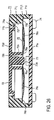
- Figs. 26 and 27 show an embodiment according to the fourth mode of carrying the invention.
- the case 71 is in the form of a square box, and the opening 71b in the surface plate 71a is circular and is substantially centered about the axis of the case 71.
- Screws 74 are inserted into openings 71f in the rear plate 71e, and are threadably engaged with bores 71g formed in the end face of the sidewall 71i of the case 71 at the comers thereof, thus securing the rear plate 71e to the sidewall 71i.
- the knob 72 has a circular top plate 72d which is positioned so as to substantially block the opening 71b.
- the top plate 72d is centrally formed with a projection 72c on its internal surface.
- a tubular portion 72e which is centered about the projection 72c is integrally formed with the internal surface of the top plate 72d.
- the tubular portion 72e has a length which is slightly less than the projection 72c.
- the top plate 72d is integrally formed with a flange 72f which has a step in a direction in which the projection 72c projects.
- a member connector 71j is formed on the internal surface of the case sidewall 71i, and has a connection surface 71j1 located toward the rear plate 71e which is substantially coplanar with the end face of the tubular portion 72e when the flange 72f abuts against the internal surface of the surface plate 71a.
- the member connector 71j is cylindrical about the axis of the opening 71b, and is unified with the internal surface of the sidewall 71i by contact therewith at four locations around the outer peripheral surface.
- the resilient member 76 has a configuration which is symmetrical with respect to the axis of the knob 72 and includes at least three linear portions which extend radially at an equi-angular interval from the tubular portion 72e to the member connector 71i to connect the case 71 and the knob 72 together. Specifically, it comprises a ring-shaped movable connector 76a, a ring-shaped case connector 76b having a greater diameter, and a body 76c including linear portions which connect between the both connectors 76a and 76b.
- the body 76c includes at least three linear portions, although sixth linear portions are shown in Fig. 7, in the form of ribbons which are disposed at an equi-angular interval. These ribbons of the body 76c are slightly curved to be convex toward the rear plate 71e.
- the connectors 76a and 76b and the body 76c are integrally formed by a resilient material such as thin metal sheet or hard resin.
- the knob connector 76a is secured to the end face of the tubular portion 72e of the knob 72 as by adhesion while the case connector 76b is secured to the connection surface 71j1 of the member connector of the case 71 as by adhesion.
- a tact switch is used as the switch 73.
- the tact switch 73 is secured to the rear plate 71e and has an actuator 73a, the projecting end face of which abuts against the end face of the projection 72c of the knob, and a reversal spring within the tact switch 73 causes the flange 72f of the knob 72 to abut against the internal surface of the surface plate 71a.
- the knob 72 is displaced toward the rear plate 71e against the reaction from an internal spring within the tact switch 73 and without producing an inclination, whereby the actuator 73a is driven into the switch case 73b, causing a reversal of the internal spring to turn the tact switch 73 on.
- the projection 72c urges the actuator 73a in a direction perpendicular to the rear plate 71e, and accordingly, the tact switch 73 operates reliably even with a weak force with a good clicking sensation and with an even stroking length.
- a stress which is applied to the reversal spring within the tact switch 73 is maintained relatively low, increasing the useful life of the reversal spring.
- a component of the depressing force which is parallel to the rear plate 71 e is suppressed by the resilient member 76, and accordingly, the knob 72 is readily displaced in a direction toward the rear plate 71e while maintaining its parallel relationship with respect to the rear plate 71e.
- the body 76c should preferably be as parallel to the rear plate 71e as possible from the standpoint of making the body 76c less susceptible to a force acting lengthwise thereof and in a direction parallel to the rear plate 71 to curve (or to deform).
- the knob connector 76a is readily displaceable with a weak force in a direction perpendicular to the rear plate 71e. Consequently, it is desirable to have a curvature of the body 76c relative to the rear plate 71e which allows the switch 73 to be reliably turned on and which is gentle enough to avoid tensioning the body 76c.
- knob 72 from the standpoint of making the knob 72 to be readily displaceable in a direction toward the rear plate 71e, it is preferred that a connection be made between a portion of the knob 72 which is located toward the center and a portion of the case 71 which is located toward the sidewall in order to increase the length of the linear body 76c.
- Fig. 30 shows a sixth embodiment as another example of the fourth mode of carrying out the invention.
- a ring-shaped resilient member 76 which is U-shaped in section has its outer periphery and inner periphery secured to the periphery of the opening 71b on the internal surface of the surface plate 71a of the case 71 and to the periphery of the knob 72 on its internal surface, respectively, as by adhesion.
- the resilient member 76 is constructed such that the body 76c extending between connectors 76b and 76a which are connected to the case 71 and the knob 72, respectively, be formed over the entire perimeter, and the resilient member 76 may be formed of a variety of materials as mentioned previously. However, in particular, a thermoplastic elastomer or a silicone rubber is suitable at this end.
- the peripheral surface portions 76c1 and 76c2 move toward each other while they move away from each other at the other end, and therefore, if this aspect is considered alone, it would appear that the knob 72 will be relatively readily displaced to the right, for example.
- the viewpoint is shifted to the center and considering opposite ends of a line which extends in a direction perpendicular to the plane of the drawing, there acts a force which causes the peripheral surface portions 76c 1 and 76c2 to be offset to the left and to the right, respectively. Because such action must be considered, it will be seen that a greater force will be required to offset the peripheral surface portion 76c1 relative to the peripheral surface portion 76c2.
- the action of the resilient member 76 is effective to cause the knob 72 to move relative to the rear plate 71e while maintaining its parallel relationship therewith.
- the ring-shaped resilient member 76 which is U-shaped in section is more effective when the both limbs of the U-shape or the both peripheral surface portions 76c1 and 76c2 are located closely relative to each other, and therefore should be connected to locations which are as close to the casing 71 and the knob 72, respectively, as possible.
- the resilient member 76 blocks a space between the surface plate 71a and the knob 72, thus providing a dust-proof effect. As indicated in broken lines in Fig. 30, when the resilient member 76 including the linear body 76c shown in Fig. 26 is also used in combination, the maneuverability against an edgewise depression is improved.
- a resilient member 76 may be constructed as shown in Figs. 31A and 31B, for example, where a body 76c disposed between a knob connector 76a and a case connector 76b is corrugated in the form of concentric circles with the both connectors 76a, 76b, thus connecting the both connectors 76a and 76b over the full perimeter.
- the material to form such an example should preferably be paper or fiber.
- a resilient member 76 comprises a single flat sheet, which is circular in this example.
- a circular opening 76d is formed at the center of the sheet, and the periphery of the circular opening 76d defines a knob connector 76a, which may be adhesively secured to the end face of the tubular portion 72e shown in Fig. 26, for example.
- Small openings 76e are formed in the outer periphery of the resilient member 76 at least three locations or at four locations as shown in Fig. 36C.
- the periphery of the small opening 76e defines the case connector 76b to be secured to the case 71. This securing operation may take place in the similar manner as securing the peripheral edge 32f shown in Fig. 8, for example.
- a construction material chosen in this instance should preferably be a thermoplastic elastomer or a silicone rubber. This makes the knob 72 to be readily displaceable in a direction toward the rear plate 71e, but hardly displaceable in a direction parallel to the rear plate 71e.
- the switch 73 is not limited to the tact switch. What is required is that the switch is turned on when the knob 72 is depressed and that when the depression is released, the resilient restoring force of the spring automatically returns the knob 72 to its original condition. The presence of the clicking sensation is not required.
- the second step switch 36 shown in Fig. 4 or switches shown in Figs. 22A and 22B may be used.
- the fifth mode of carrying out the invention is applied to a depression responsive two-step switch unit where the knob 72 which operates on the second-step switch 73 is retained by a resilient member 76.
- the second step switch 36 corresponds to the switch 73
- the associated knob 72 comprises the knob 32, the key operation base 33, the first step switch 34s and the reinforcing plate 35 which are unified.
- the marginal portion 32f is secured to the case 39 at a plurality of points while the remainder remains free, and this corresponds to a modification of the resilient member 76 shown in Fig. 31C.
- the second embodiment mentioned previously with reference to Fig. 10 is also equivalent to an embodiment of the fifth mode of carrying out the invention.
- the knob 72 remains similar to the first embodiment
- the second step switch 73 corresponds to the second step switch 36 shown in Fig. 10
- the resilient member 76 comprises the marginal portion 32f which is U-shaped in section, this corresponding to one shown in Fig. 30.
- a movable portion including each first step switch 34s which is used in the first to the third mode of carrying out the invention or the portion which drives the second step switch 36 is chosen as a knob 72 in another embodiment of the fifth mode of carrying out the invention which uses the resilient member 76 used in the fourth mode of carrying out the invention.
- Such an embodiment is illustrated by a combination of the first and the fifth embodiment, which is shown in section in Fig. 32 even though a duplicated description is omitted.
- a member connector 71j is formed on the internal surface of the sidewall 71i at a location toward the rear plate 71e, and has a connecting surface 71j2 toward the cover (surface plate) 31, to which the case connector 76b of the resilient member 76 is secured.
- the key operation base 33 and the surface plate 39j and/or the reinforcing plate 35 or the projection 35b thereon and the case sidewalls 39a, 39b are connected together by the resilient member 76.
- a first step switch used in the embodiment for the fifth mode of carrying out the invention is not limited to those mentioned above in connection with the first to the third mode of carrying out the invention as well as modifications thereof, but may be a membrane switch which is covered with the surface sheet shown in Figs. 1 to 3, for example, or may be a touch panel shown in Fig. 21A or 21B which is arranged to be directly depressed from the exterior.
- a knob 72 is retained by a case 71 through a resilient member 76 1 having a linear body which is used in the fifth embodiment and a resilient member 76 2 having a ring-shaped body which is U-shaped in section and which is used in the sixth embodiment.
- a portion of the knob 72 which is located close to the projecting end of the projection 72c and another portion thereof which is located close to the internal surface of the top plate 72d are retained by the case 71 through different kinds of resilient members 76 1 and 76 2 .
- the knob 72 is retained by the case 71 through two resilient members 76 1 and 76 2 which are spaced apart in a direction perpendicular to the rear plate 71e.
- a first step switch 79 such as a membrane switch or a touch panel is disposed on the top plate 72d of the knob 72. While not shown, whatever the construction of the first step switch 79, a band-shaped flexible cable (FBC) including external connection lead wires for respective switches in the first step switch assembly 79 is taken out from the interior of the case 71, as illustrated by FBC8 in Figs. 1 to 3, for example.
- FBC band-shaped flexible cable
- the second step switch 73 may comprise a variety of switches without being limited to the tact switch, in the similar manner as mentioned above.
Landscapes
- Push-Button Switches (AREA)
Abstract
Description
Claims (21)
- A depression responsive switch unit in which a switch is turned on in response to a depression operation; comprisinga case including a surface plate in which an opening is formed;a reinforcing plate disposed opposite to a rear plate of the case and disposed within the case so as to be reciprocable with respect to the rear plate;a second step switch interposed between the reinforcing plate and the rear plate and adapted to be operated on by a movement of the reinforcing plate toward the rear plate;a plurality of first step switches disposed on the reinforcing plate on the side located toward the surface plate;a key operation base disposed on the case in a manner to block the opening in the surface plate and formed with depression openings each located corresponding to each first step switch;and a knob disposed on the key operation base on the opposite side from the reinforcing plate;the knob including an elastic sheet which is formed of a thermoplastic elastomer or a silicone rubber and having a marginal portion which is retained by the case, depressing pieces formed on the elastic sheet in a manner corresponding to each first step switch and having a depressed surface on the front side of the elastic sheet and disposed in each depression opening, and a small projection projecting from each depressing piece in the opposite direction from the depressed surface to be located close to or in contact with the first step switch.
- A depression responsive switch unit according to Claim 1, in which the elastic sheet, the depressing pieces and the small projections are integrally formed with a thermoplastic elastomer or silicone rubber.
- A depression responsive switch unit according to Claim 1 in which the elastic sheet is formed with an opening in a manner corresponding to each depressing piece, the depressing piece being passed through a corresponding one of the openings, a depressing piece having a flange which is disposed in abutment against and secured to the elastic sheet, each depressing piece, its flange and corresponding small projection being integrally formed with a hard resin.
- A depression responsive switch unit according to Claim 1 in which each depressing piece comprises an external portion which is exposed externally of the elastic sheet and a remainder, the external portion being formed by a hard resin while the remainder of the depressing piece being integrally formed of a thermoplastic elastomer or silicone rubber together with the elastic sheet and the small projection.
- A depression responsive switch unit according to Claim 1 in which the marginal portion of the elastic sheet is held sandwiched by the case at only a plurality of locations to be secured.
- A depression responsive switch unit according to Claim 1 in which the marginal portion of the elastic sheet is formed with a ring which is U-shaped in section around the full perimeter of the knob at a location inside thereof which is retained by the case.
- A depression responsive switch unit in which a switch is turned on in response to a depression operation comprisinga case including a surface place in which an opening is formed;a reinforcing plate disposed opposite to a rear plate of the case and disposed within the case so as to be reciprocable relative to the rear plate;a second step switch interposed between the reinforcing plate and the rear plate and operated on by a movement of the reinforcing plate toward the rear plate;a plurality of first step switches disposed on the reinforcing plate on the side located toward the surface plate;a key operation base disposed on the case so as to block the opening in the surface plate and formed with depression openings corresponding to the location of each first step switch;and a knob disposed between the reinforcing plate and the key operation base;the knob including an elastic sheet which is formed of a thermoplastic elastomer or a silicone rubber and having a marginal portion which is held sandwiched between the key operation base and the reinforcing plate to be secured, depressing pieces formed on the elastic sheet so as to correspond to each first step switch, each depressing piece being disposed in a depression opening formed in the key operation base, and a small projection projecting from elastic sheet for each depressing piece to be located close to or in contact with the first step switch.
- A depression responsive switch unit according to Claim 7 in which the elastic sheet is formed with a plurality of air gap formations which project toward the reinforcing plate and which are located on the opposite sides of each small projection and spaced therefrom by an equal distance, the air gap formations being in contact with the reinforcing plate.
- A depression responsive switch unit according to Claim 7 in which the elastic sheet is formed with a small opening in a manner corresponding to each depressing piece, the depressing piece having a depressed surface and a mounting surface which is located on the opposite side from the depressed surface and which is disposed in abutment against and secured to the elastic sheet, the small projection being integrally formed centrally in the mounting surface, the small projection extending through the small opening to project toward the reinforcing plate from the elastic sheet, each depressing piece and small projection being integrally formed from a hard resin.
- A depression responsive switch unit according to Claim 7, in which the elastic sheet, the depressing piece and the small projection are integrally formed by a thermoplastic elastomer or a silicone rubber.
- A depression responsive switch unit according to Claim 7, in which the elastic sheet and the small projection are integrally formed of a thermoplastic elastomer or silicone rubber while the depressing piece is formed of a hard resin and is secured to the elastic sheet as is the corresponding small projection.
- A depression responsive switch unit in which a switch is turned on in response to a depression operation, comprisinga case including a surface plate in which an opening is formed;a reinforcing plate disposed opposite to a rear plate of the case and disposed within the case so as to be reciprocable with respect to the rear plate;a second step switch interposed between the reinforcing plate and the rear plate and operated on by a movement of the reinforcing plate toward the rear plate;a plurality of first step switches disposed on the reinforcing plate on the side located toward the surface plate;a key operation base disposed on the case in a manner to block the opening in the surface plate and having depression openings formed therein in a manner corresponding to the location of each first step switch;and a knob disposed on the key operation base on the opposite side from the reinforcing plate;the knob including an elastic sheet which is formed of a thermoplastic elastomer or silicone rubber and having a marginal portion which is secured by being held sandwiched between the key operation base and the reinforcing plate, depressing pieces formed on the elastic sheet in a manner corresponding to each first step switch and each having a depressed surface on the front side of the elastic sheet and each disposed in the depression opening, and a small projection projecting from each depressing piece in the opposite direction from the depressed surface to be located close to or in contact with the first step switch.
- A depression responsive switch unit according to Claim 12 in which the elastic sheet is formed with openings to receive each depressing piece, each depressing piece having a flange which is disposed in abutment against and secured to the elastic sheet, each depressing piece, its flange and associated small projection being integrally formed from a hard resin.
- A depression responsive switch unit according to Claim 12 in which the elastic sheet, the depressing piece and the small projection are integrally formed by a thermoplastic elastomer or a silicone rubber.
- A depression responsive switch unit according to Claim 12 in which each depressing piece has an external portion which is exposed externally of the elastic sheet and a remainder, the external portion being formed from a hard resin while the remainder of the depression piece, the elastic sheet and the small projection being integrally formed of a thermoplastic elastomer or silicone rubber.
- A depression responsive switch unit in which a switch is turned on in response to the depression of a knob, comprisinga case including a surface plate in which an opening is formed;a knob disposed in the case so as to block the opening;a resilient member connecting the knob to the case in a manner such that the knob is readily displaceable in the direction of a depression which is perpendicular to the surface plate and is hardly displaceable in a direction perpendicular to the direction of depression;and a switch disposed within the case on the case rear plate and operated on by a displacement of the knob as it is depressed.
- A depression responsive switch unit according to Claim 16 in which the resilient member comprises at least three linear members which are connected to the central portion of the knob and a sidewall of the case at an equi-angular interval.
- A depression responsive switch unit according to Claim 16 in which the resilient member is a ring which is U-shaped in section and connected to the marginal portion of the knob and to the opening around the full perimeter.
- A depression responsive switch unit according to Claim 16 in which the resilient member comprises a first and a second resilient member which connect between the knob and the case at locations which are spaced apart in a direction perpendicular to the rear plate.
- A depression responsive switch unit according to Claim 16 in which a first step switch is formed on the knob which can be turned on by a weak depression which cannot turn the switch on.
- A depression responsive switch unit according to Claim 20 in which the knob comprises a reinforcing plate, a plurality of first step switches disposed on the reinforcing plate, a key operation base secured to the reinforcing plate and having openings each corresponding to each first step switch, a depressing piece which is at least partly disposed within each opening, an elastic sheet carrying the depressing pieces and formed of a thermoplastic elastomer or silicone rubber, and a small projection projecting from each depressing piece in a direction opposite from the depressed surface to be located close to or in contact with the first step switch.
Applications Claiming Priority (4)
| Application Number | Priority Date | Filing Date | Title |
|---|---|---|---|
| JP2003108210 | 2003-04-11 | ||
| JP2003108210 | 2003-04-11 | ||
| JP2004095640 | 2004-03-29 | ||
| JP2004095640A JP4344639B2 (en) | 2003-04-11 | 2004-03-29 | Press operation type switch unit |
Publications (2)
| Publication Number | Publication Date |
|---|---|
| EP1467392A2 true EP1467392A2 (en) | 2004-10-13 |
| EP1467392A3 EP1467392A3 (en) | 2005-09-07 |
Family
ID=32871261
Family Applications (1)
| Application Number | Title | Priority Date | Filing Date |
|---|---|---|---|
| EP04008389A Withdrawn EP1467392A3 (en) | 2003-04-11 | 2004-04-07 | Depression responsive switch unit |
Country Status (3)
| Country | Link |
|---|---|
| US (1) | US7019225B2 (en) |
| EP (1) | EP1467392A3 (en) |
| JP (1) | JP4344639B2 (en) |
Cited By (22)
| Publication number | Priority date | Publication date | Assignee | Title |
|---|---|---|---|---|
| WO2008045833A1 (en) * | 2006-10-11 | 2008-04-17 | Apple Inc. | Gimballed scroll wheel |
| WO2008045830A1 (en) * | 2006-10-11 | 2008-04-17 | Apple Inc. | Method and apparatus for implementing multiple push buttons in a user input device |
| WO2008054955A3 (en) * | 2006-10-11 | 2008-09-18 | Apple Inc | Sensor configurations in a user input device |
| US7795553B2 (en) | 2006-09-11 | 2010-09-14 | Apple Inc. | Hybrid button |
| AU2007313960B2 (en) * | 2007-06-18 | 2010-09-30 | Apple Inc. | Sensor configurations in a user input device |
| US7880729B2 (en) | 2005-10-11 | 2011-02-01 | Apple Inc. | Center button isolation ring |
| CN102455802A (en) * | 2010-10-20 | 2012-05-16 | Nxp股份有限公司 | User-interface for controlling a data processing system using a joystick |
| US8330061B2 (en) | 2007-09-04 | 2012-12-11 | Apple Inc. | Compact input device |
| US8395590B2 (en) | 2008-12-17 | 2013-03-12 | Apple Inc. | Integrated contact switch and touch sensor elements |
| US8416198B2 (en) | 2007-12-03 | 2013-04-09 | Apple Inc. | Multi-dimensional scroll wheel |
| US8482530B2 (en) | 2006-11-13 | 2013-07-09 | Apple Inc. | Method of capacitively sensing finger position |
| CN103545136A (en) * | 2012-07-16 | 2014-01-29 | 富泰华工业(深圳)有限公司 | Electronic device and power button module |
| US8743060B2 (en) | 2006-07-06 | 2014-06-03 | Apple Inc. | Mutual capacitance touch sensing device |
| US8820133B2 (en) | 2008-02-01 | 2014-09-02 | Apple Inc. | Co-extruded materials and methods |
| US8872771B2 (en) | 2009-07-07 | 2014-10-28 | Apple Inc. | Touch sensing device having conductive nodes |
| US9367151B2 (en) | 2005-12-30 | 2016-06-14 | Apple Inc. | Touch pad with symbols based on mode |
| US9454256B2 (en) | 2008-03-14 | 2016-09-27 | Apple Inc. | Sensor configurations of an input device that are switchable based on mode |
| US9654104B2 (en) | 2007-07-17 | 2017-05-16 | Apple Inc. | Resistive force sensor with capacitive discrimination |
| US9977518B2 (en) | 2001-10-22 | 2018-05-22 | Apple Inc. | Scrolling based on rotational movement |
| US10139870B2 (en) | 2006-07-06 | 2018-11-27 | Apple Inc. | Capacitance sensing electrode with integrated I/O mechanism |
| US10353565B2 (en) | 2002-02-25 | 2019-07-16 | Apple Inc. | Input apparatus and button arrangement for handheld device |
| US10866718B2 (en) | 2007-09-04 | 2020-12-15 | Apple Inc. | Scrolling techniques for user interfaces |
Families Citing this family (40)
| Publication number | Priority date | Publication date | Assignee | Title |
|---|---|---|---|---|
| US7345671B2 (en) * | 2001-10-22 | 2008-03-18 | Apple Inc. | Method and apparatus for use of rotational user inputs |
| US7499040B2 (en) | 2003-08-18 | 2009-03-03 | Apple Inc. | Movable touch pad with added functionality |
| US20070152977A1 (en) | 2005-12-30 | 2007-07-05 | Apple Computer, Inc. | Illuminated touchpad |
| US8059099B2 (en) | 2006-06-02 | 2011-11-15 | Apple Inc. | Techniques for interactive input to portable electronic devices |
| US7495659B2 (en) | 2003-11-25 | 2009-02-24 | Apple Inc. | Touch pad for handheld device |
| CN101661357B (en) * | 2004-08-16 | 2013-07-03 | 苹果公司 | Touch sensitive device and method of increasing the spatial resolution of touch sensitive device |
| DE102005014935A1 (en) * | 2004-11-30 | 2006-06-14 | Diehl Ako Stiftung & Co. Kg | Operating device for a household electrical appliance |
| FR2879803B1 (en) * | 2004-12-20 | 2007-01-19 | Dav Sa | TOUCH SURFACE ACTIVATION DEVICE, IN PARTICULAR FOR CONTROLS OF A VEHICLE |
| US20070008305A1 (en) * | 2005-06-28 | 2007-01-11 | Visteon Global Technologies, Inc. | Multiple function radio bezel interface |
| US7378605B2 (en) * | 2005-07-19 | 2008-05-27 | Giga-Byte Communications Inc. | Input component |
| US7671837B2 (en) | 2005-09-06 | 2010-03-02 | Apple Inc. | Scrolling input arrangements using capacitive sensors on a flexible membrane |
| JP4946343B2 (en) * | 2005-10-24 | 2012-06-06 | パナソニック株式会社 | Switch device and input device using the same |
| DE202006004575U1 (en) * | 2006-03-22 | 2006-05-18 | Trw Automotive Electronics & Components Gmbh & Co. Kg | switch module |
| JP2008003714A (en) * | 2006-06-20 | 2008-01-10 | Toshiba Corp | Component coupling structure and electronic equipment |
| US9360967B2 (en) | 2006-07-06 | 2016-06-07 | Apple Inc. | Mutual capacitance touch sensing device |
| JP2008310971A (en) * | 2007-06-12 | 2008-12-25 | Mitsubishi Electric Corp | Button structure of electrical equipment |
| USD585842S1 (en) * | 2007-08-29 | 2009-02-03 | Mitsumi Electric Co., Ltd | Actuator |
| USD585843S1 (en) * | 2007-08-29 | 2009-02-03 | Mitsumi Electric Co., Ltd | Actuator |
| US8125461B2 (en) | 2008-01-11 | 2012-02-28 | Apple Inc. | Dynamic input graphic display |
| CN101599376B (en) * | 2008-06-06 | 2012-06-13 | 深圳富泰宏精密工业有限公司 | Press key structure |
| TWI410995B (en) * | 2008-07-04 | 2013-10-01 | Chi Mei Comm Systems Inc | Key mechanism |
| US20100058251A1 (en) * | 2008-08-27 | 2010-03-04 | Apple Inc. | Omnidirectional gesture detection |
| US20100060568A1 (en) * | 2008-09-05 | 2010-03-11 | Apple Inc. | Curved surface input device with normalized capacitive sensing |
| US8816967B2 (en) | 2008-09-25 | 2014-08-26 | Apple Inc. | Capacitive sensor having electrodes arranged on the substrate and the flex circuit |
| USD607852S1 (en) * | 2008-12-23 | 2010-01-12 | Magnadyne Corporation | Communication controller |
| US9354751B2 (en) | 2009-05-15 | 2016-05-31 | Apple Inc. | Input device with optimized capacitive sensing |
| JP4947179B2 (en) * | 2010-03-30 | 2012-06-06 | 株式会社デンソー | Portable transmitter |
| CN102387678A (en) * | 2010-09-03 | 2012-03-21 | 鸿富锦精密工业(深圳)有限公司 | Electronic device |
| US9373463B2 (en) * | 2012-09-11 | 2016-06-21 | Apple Inc. | Systems and methods for providing inputs to an electronic device with a button assembly |
| JP5615886B2 (en) * | 2012-10-17 | 2014-10-29 | 株式会社東海理化電機製作所 | Operating device |
| US9972459B1 (en) * | 2013-09-09 | 2018-05-15 | Apple Inc. | Tactile switch assembly in an electronic device |
| JP1527004S (en) * | 2014-01-02 | 2015-06-22 | ||
| CN104409263B (en) * | 2014-11-11 | 2017-05-24 | 青岛海信移动通信技术股份有限公司 | Expansion key and mobile terminal |
| JP6390970B2 (en) * | 2015-07-22 | 2018-09-19 | パナソニックIpマネジメント株式会社 | Input device and steering input device |
| KR102423148B1 (en) * | 2015-11-26 | 2022-07-21 | 삼성전자주식회사 | Methode for obtaining user input and electronic device thereof |
| JP6897800B2 (en) | 2018-01-12 | 2021-07-07 | 株式会社村田製作所 | Electronics |
| TWI702626B (en) * | 2018-03-30 | 2020-08-21 | 英屬開曼群島商康而富控股股份有限公司 | Touch button with better pressing feel |
| US11907016B2 (en) * | 2021-03-12 | 2024-02-20 | Apple Inc. | Electronic device |
| DE202021003830U1 (en) | 2021-12-20 | 2022-07-19 | Mfk Gmbh Klingelanlagen | How the anti-vandalism bell button works |
| JP7746561B2 (en) | 2022-05-18 | 2025-09-30 | アルプスアルパイン株式会社 | Input device and assembly method |
Family Cites Families (11)
| Publication number | Priority date | Publication date | Assignee | Title |
|---|---|---|---|---|
| FR1316747A (en) | 1962-02-01 | 1963-02-01 | Single and multiple contact (floating) contactor | |
| US5121091A (en) * | 1989-09-08 | 1992-06-09 | Matsushita Electric Industrial Co., Ltd. | Panel switch |
| JP3219353B2 (en) * | 1994-08-26 | 2001-10-15 | アルプス電気株式会社 | Rotary switch and multi-directional input device |
| US5508479A (en) * | 1994-11-17 | 1996-04-16 | Schooley; John L. | Elastomeric rocker switch assembly |
| JP3014604B2 (en) * | 1994-11-18 | 2000-02-28 | 株式会社東海理化電機製作所 | switch |
| JPH08315682A (en) | 1995-05-17 | 1996-11-29 | Japan Aviation Electron Ind Ltd | Switch unit with click feeling |
| US5744765A (en) * | 1995-06-19 | 1998-04-28 | Sumitomo Wiring Systems, Ltd. | Lever switch with support walls for supporting movable contact points and method of detecting an operating direction of a lever switch |
| JP3306311B2 (en) | 1996-08-29 | 2002-07-24 | アルプス電気株式会社 | Push type switch |
| JP3951493B2 (en) * | 1999-03-15 | 2007-08-01 | 松下電器産業株式会社 | Multi-directional operation switch and composite switch using the same |
| US6492602B2 (en) * | 2000-02-10 | 2002-12-10 | Alps Electric Co., Ltd. | Two-position pushbutton switch |
| JP2001357758A (en) * | 2000-06-12 | 2001-12-26 | Alps Electric Co Ltd | Multi-operation input device |
-
2004
- 2004-03-29 JP JP2004095640A patent/JP4344639B2/en not_active Expired - Fee Related
- 2004-04-06 US US10/819,568 patent/US7019225B2/en not_active Expired - Fee Related
- 2004-04-07 EP EP04008389A patent/EP1467392A3/en not_active Withdrawn
Cited By (29)
| Publication number | Priority date | Publication date | Assignee | Title |
|---|---|---|---|---|
| US9977518B2 (en) | 2001-10-22 | 2018-05-22 | Apple Inc. | Scrolling based on rotational movement |
| US10353565B2 (en) | 2002-02-25 | 2019-07-16 | Apple Inc. | Input apparatus and button arrangement for handheld device |
| US7880729B2 (en) | 2005-10-11 | 2011-02-01 | Apple Inc. | Center button isolation ring |
| US9367151B2 (en) | 2005-12-30 | 2016-06-14 | Apple Inc. | Touch pad with symbols based on mode |
| US8743060B2 (en) | 2006-07-06 | 2014-06-03 | Apple Inc. | Mutual capacitance touch sensing device |
| US10890953B2 (en) | 2006-07-06 | 2021-01-12 | Apple Inc. | Capacitance sensing electrode with integrated I/O mechanism |
| US10359813B2 (en) | 2006-07-06 | 2019-07-23 | Apple Inc. | Capacitance sensing electrode with integrated I/O mechanism |
| US10139870B2 (en) | 2006-07-06 | 2018-11-27 | Apple Inc. | Capacitance sensing electrode with integrated I/O mechanism |
| US7795553B2 (en) | 2006-09-11 | 2010-09-14 | Apple Inc. | Hybrid button |
| US8274479B2 (en) | 2006-10-11 | 2012-09-25 | Apple Inc. | Gimballed scroll wheel |
| WO2008045833A1 (en) * | 2006-10-11 | 2008-04-17 | Apple Inc. | Gimballed scroll wheel |
| WO2008045830A1 (en) * | 2006-10-11 | 2008-04-17 | Apple Inc. | Method and apparatus for implementing multiple push buttons in a user input device |
| WO2008054955A3 (en) * | 2006-10-11 | 2008-09-18 | Apple Inc | Sensor configurations in a user input device |
| US10180732B2 (en) | 2006-10-11 | 2019-01-15 | Apple Inc. | Gimballed scroll wheel |
| US8482530B2 (en) | 2006-11-13 | 2013-07-09 | Apple Inc. | Method of capacitively sensing finger position |
| AU2007313960B2 (en) * | 2007-06-18 | 2010-09-30 | Apple Inc. | Sensor configurations in a user input device |
| US9654104B2 (en) | 2007-07-17 | 2017-05-16 | Apple Inc. | Resistive force sensor with capacitive discrimination |
| US12159028B2 (en) | 2007-09-04 | 2024-12-03 | Apple Inc. | Scrolling techniques for user interfaces |
| US10866718B2 (en) | 2007-09-04 | 2020-12-15 | Apple Inc. | Scrolling techniques for user interfaces |
| US8330061B2 (en) | 2007-09-04 | 2012-12-11 | Apple Inc. | Compact input device |
| US8416198B2 (en) | 2007-12-03 | 2013-04-09 | Apple Inc. | Multi-dimensional scroll wheel |
| US8820133B2 (en) | 2008-02-01 | 2014-09-02 | Apple Inc. | Co-extruded materials and methods |
| US9454256B2 (en) | 2008-03-14 | 2016-09-27 | Apple Inc. | Sensor configurations of an input device that are switchable based on mode |
| US8395590B2 (en) | 2008-12-17 | 2013-03-12 | Apple Inc. | Integrated contact switch and touch sensor elements |
| US8872771B2 (en) | 2009-07-07 | 2014-10-28 | Apple Inc. | Touch sensing device having conductive nodes |
| CN102455802A (en) * | 2010-10-20 | 2012-05-16 | Nxp股份有限公司 | User-interface for controlling a data processing system using a joystick |
| US9019206B2 (en) | 2010-10-20 | 2015-04-28 | Nxp, B.V. | User-interface for controlling a data processing system using a joystick |
| CN103545136B (en) * | 2012-07-16 | 2015-12-16 | 富泰华工业(深圳)有限公司 | Electronic installation and power knob module thereof |
| CN103545136A (en) * | 2012-07-16 | 2014-01-29 | 富泰华工业(深圳)有限公司 | Electronic device and power button module |
Also Published As
| Publication number | Publication date |
|---|---|
| EP1467392A3 (en) | 2005-09-07 |
| JP4344639B2 (en) | 2009-10-14 |
| JP2004327430A (en) | 2004-11-18 |
| US20040200699A1 (en) | 2004-10-14 |
| US7019225B2 (en) | 2006-03-28 |
Similar Documents
| Publication | Publication Date | Title |
|---|---|---|
| US7019225B2 (en) | Depression responsive switch unit | |
| US5136131A (en) | Push-button switch including a sheet provided with a plurality of domed members | |
| US4839474A (en) | Switches and keyboards | |
| US20140090967A1 (en) | Two-step switch | |
| US20090015549A1 (en) | Accepting User Input | |
| JP6929352B2 (en) | Touch panel button structure, touch panel buttons, and electronic devices | |
| US11186176B2 (en) | Multifunctional switch device | |
| JP2007213964A (en) | Operation button device | |
| JP2003100170A (en) | Switch unit | |
| US20100032276A1 (en) | Key sheet | |
| JP2001155576A (en) | Illuminated pushbutton switch members | |
| JPH06275169A (en) | Keyboard switch | |
| JP2007188907A (en) | Press operation type switch unit | |
| JPH1139984A (en) | EL illuminated switch | |
| EP1164606B1 (en) | Laminate key sheet | |
| TWM583116U (en) | Rotary push switch with touch screen | |
| JPH11126536A (en) | Cover member for push button switch and push button switch | |
| JP2003323827A (en) | Member for push button switch and method of manufacturing the same | |
| JPH10188727A (en) | Membrane switch | |
| JP2003077366A (en) | Switch unit | |
| JP2002075116A (en) | Cover member for push button switch | |
| US20030137490A1 (en) | Computer mouse | |
| JP2020170682A (en) | Switch device | |
| JP3541317B2 (en) | Sliding pointing device | |
| JPH0451382Y2 (en) |
Legal Events
| Date | Code | Title | Description |
|---|---|---|---|
| PUAI | Public reference made under article 153(3) epc to a published international application that has entered the european phase |
Free format text: ORIGINAL CODE: 0009012 |
|
| 17P | Request for examination filed |
Effective date: 20040407 |
|
| AK | Designated contracting states |
Kind code of ref document: A2 Designated state(s): AT BE BG CH CY CZ DE DK EE ES FI FR GB GR HU IE IT LI LU MC NL PL PT RO SE SI SK TR |
|
| AX | Request for extension of the european patent |
Extension state: AL HR LT LV MK |
|
| PUAL | Search report despatched |
Free format text: ORIGINAL CODE: 0009013 |
|
| AK | Designated contracting states |
Kind code of ref document: A3 Designated state(s): AT BE BG CH CY CZ DE DK EE ES FI FR GB GR HU IE IT LI LU MC NL PL PT RO SE SI SK TR |
|
| AX | Request for extension of the european patent |
Extension state: AL HR LT LV MK |
|
| AKX | Designation fees paid |
Designated state(s): DE FI FR GB |
|
| STAA | Information on the status of an ep patent application or granted ep patent |
Free format text: STATUS: THE APPLICATION IS DEEMED TO BE WITHDRAWN |
|
| 18D | Application deemed to be withdrawn |
Effective date: 20091103 |