EP1467263A1 - Moving image holography reproducing device and color moving image holography reproducing device - Google Patents
Moving image holography reproducing device and color moving image holography reproducing device Download PDFInfo
- Publication number
- EP1467263A1 EP1467263A1 EP03701727A EP03701727A EP1467263A1 EP 1467263 A1 EP1467263 A1 EP 1467263A1 EP 03701727 A EP03701727 A EP 03701727A EP 03701727 A EP03701727 A EP 03701727A EP 1467263 A1 EP1467263 A1 EP 1467263A1
- Authority
- EP
- European Patent Office
- Prior art keywords
- image
- light
- reproducing device
- moving
- color
- Prior art date
- Legal status (The legal status is an assumption and is not a legal conclusion. Google has not performed a legal analysis and makes no representation as to the accuracy of the status listed.)
- Withdrawn
Links
Images



Classifications
-
- G—PHYSICS
- G03—PHOTOGRAPHY; CINEMATOGRAPHY; ANALOGOUS TECHNIQUES USING WAVES OTHER THAN OPTICAL WAVES; ELECTROGRAPHY; HOLOGRAPHY
- G03H—HOLOGRAPHIC PROCESSES OR APPARATUS
- G03H1/00—Holographic processes or apparatus using light, infrared or ultraviolet waves for obtaining holograms or for obtaining an image from them; Details peculiar thereto
- G03H1/22—Processes or apparatus for obtaining an optical image from holograms
- G03H1/2294—Addressing the hologram to an active spatial light modulator
-
- G—PHYSICS
- G03—PHOTOGRAPHY; CINEMATOGRAPHY; ANALOGOUS TECHNIQUES USING WAVES OTHER THAN OPTICAL WAVES; ELECTROGRAPHY; HOLOGRAPHY
- G03H—HOLOGRAPHIC PROCESSES OR APPARATUS
- G03H1/00—Holographic processes or apparatus using light, infrared or ultraviolet waves for obtaining holograms or for obtaining an image from them; Details peculiar thereto
- G03H1/22—Processes or apparatus for obtaining an optical image from holograms
- G03H1/2286—Particular reconstruction light ; Beam properties
-
- G—PHYSICS
- G03—PHOTOGRAPHY; CINEMATOGRAPHY; ANALOGOUS TECHNIQUES USING WAVES OTHER THAN OPTICAL WAVES; ELECTROGRAPHY; HOLOGRAPHY
- G03H—HOLOGRAPHIC PROCESSES OR APPARATUS
- G03H1/00—Holographic processes or apparatus using light, infrared or ultraviolet waves for obtaining holograms or for obtaining an image from them; Details peculiar thereto
- G03H1/04—Processes or apparatus for producing holograms
- G03H1/08—Synthesising holograms, i.e. holograms synthesized from objects or objects from holograms
- G03H1/0808—Methods of numerical synthesis, e.g. coherent ray tracing [CRT], diffraction specific
-
- G—PHYSICS
- G03—PHOTOGRAPHY; CINEMATOGRAPHY; ANALOGOUS TECHNIQUES USING WAVES OTHER THAN OPTICAL WAVES; ELECTROGRAPHY; HOLOGRAPHY
- G03H—HOLOGRAPHIC PROCESSES OR APPARATUS
- G03H1/00—Holographic processes or apparatus using light, infrared or ultraviolet waves for obtaining holograms or for obtaining an image from them; Details peculiar thereto
- G03H1/22—Processes or apparatus for obtaining an optical image from holograms
- G03H1/2249—Holobject properties
-
- G—PHYSICS
- G03—PHOTOGRAPHY; CINEMATOGRAPHY; ANALOGOUS TECHNIQUES USING WAVES OTHER THAN OPTICAL WAVES; ELECTROGRAPHY; HOLOGRAPHY
- G03H—HOLOGRAPHIC PROCESSES OR APPARATUS
- G03H1/00—Holographic processes or apparatus using light, infrared or ultraviolet waves for obtaining holograms or for obtaining an image from them; Details peculiar thereto
- G03H1/22—Processes or apparatus for obtaining an optical image from holograms
- G03H1/2202—Reconstruction geometries or arrangements
- G03H1/2205—Reconstruction geometries or arrangements using downstream optical component
- G03H2001/221—Element having optical power, e.g. field lens
-
- G—PHYSICS
- G03—PHOTOGRAPHY; CINEMATOGRAPHY; ANALOGOUS TECHNIQUES USING WAVES OTHER THAN OPTICAL WAVES; ELECTROGRAPHY; HOLOGRAPHY
- G03H—HOLOGRAPHIC PROCESSES OR APPARATUS
- G03H1/00—Holographic processes or apparatus using light, infrared or ultraviolet waves for obtaining holograms or for obtaining an image from them; Details peculiar thereto
- G03H1/22—Processes or apparatus for obtaining an optical image from holograms
- G03H1/2202—Reconstruction geometries or arrangements
- G03H2001/2223—Particular relationship between light source, hologram and observer
- G03H2001/2231—Reflection reconstruction
-
- G—PHYSICS
- G03—PHOTOGRAPHY; CINEMATOGRAPHY; ANALOGOUS TECHNIQUES USING WAVES OTHER THAN OPTICAL WAVES; ELECTROGRAPHY; HOLOGRAPHY
- G03H—HOLOGRAPHIC PROCESSES OR APPARATUS
- G03H1/00—Holographic processes or apparatus using light, infrared or ultraviolet waves for obtaining holograms or for obtaining an image from them; Details peculiar thereto
- G03H1/22—Processes or apparatus for obtaining an optical image from holograms
- G03H1/2249—Holobject properties
- G03H2001/2263—Multicoloured holobject
-
- G—PHYSICS
- G03—PHOTOGRAPHY; CINEMATOGRAPHY; ANALOGOUS TECHNIQUES USING WAVES OTHER THAN OPTICAL WAVES; ELECTROGRAPHY; HOLOGRAPHY
- G03H—HOLOGRAPHIC PROCESSES OR APPARATUS
- G03H1/00—Holographic processes or apparatus using light, infrared or ultraviolet waves for obtaining holograms or for obtaining an image from them; Details peculiar thereto
- G03H1/22—Processes or apparatus for obtaining an optical image from holograms
- G03H1/2249—Holobject properties
- G03H2001/2263—Multicoloured holobject
- G03H2001/2271—RGB holobject
-
- G—PHYSICS
- G03—PHOTOGRAPHY; CINEMATOGRAPHY; ANALOGOUS TECHNIQUES USING WAVES OTHER THAN OPTICAL WAVES; ELECTROGRAPHY; HOLOGRAPHY
- G03H—HOLOGRAPHIC PROCESSES OR APPARATUS
- G03H2210/00—Object characteristics
- G03H2210/30—3D object
-
- G—PHYSICS
- G03—PHOTOGRAPHY; CINEMATOGRAPHY; ANALOGOUS TECHNIQUES USING WAVES OTHER THAN OPTICAL WAVES; ELECTROGRAPHY; HOLOGRAPHY
- G03H—HOLOGRAPHIC PROCESSES OR APPARATUS
- G03H2222/00—Light sources or light beam properties
- G03H2222/10—Spectral composition
- G03H2222/17—White light
- G03H2222/18—RGB trichrome light
-
- G—PHYSICS
- G03—PHOTOGRAPHY; CINEMATOGRAPHY; ANALOGOUS TECHNIQUES USING WAVES OTHER THAN OPTICAL WAVES; ELECTROGRAPHY; HOLOGRAPHY
- G03H—HOLOGRAPHIC PROCESSES OR APPARATUS
- G03H2222/00—Light sources or light beam properties
- G03H2222/20—Coherence of the light source
- G03H2222/22—Spatial coherence
-
- G—PHYSICS
- G03—PHOTOGRAPHY; CINEMATOGRAPHY; ANALOGOUS TECHNIQUES USING WAVES OTHER THAN OPTICAL WAVES; ELECTROGRAPHY; HOLOGRAPHY
- G03H—HOLOGRAPHIC PROCESSES OR APPARATUS
- G03H2222/00—Light sources or light beam properties
- G03H2222/20—Coherence of the light source
- G03H2222/23—Temporal coherence
-
- G—PHYSICS
- G03—PHOTOGRAPHY; CINEMATOGRAPHY; ANALOGOUS TECHNIQUES USING WAVES OTHER THAN OPTICAL WAVES; ELECTROGRAPHY; HOLOGRAPHY
- G03H—HOLOGRAPHIC PROCESSES OR APPARATUS
- G03H2222/00—Light sources or light beam properties
- G03H2222/20—Coherence of the light source
- G03H2222/24—Low coherence light normally not allowing valuable record or reconstruction
-
- G—PHYSICS
- G03—PHOTOGRAPHY; CINEMATOGRAPHY; ANALOGOUS TECHNIQUES USING WAVES OTHER THAN OPTICAL WAVES; ELECTROGRAPHY; HOLOGRAPHY
- G03H—HOLOGRAPHIC PROCESSES OR APPARATUS
- G03H2222/00—Light sources or light beam properties
- G03H2222/34—Multiple light sources
-
- G—PHYSICS
- G03—PHOTOGRAPHY; CINEMATOGRAPHY; ANALOGOUS TECHNIQUES USING WAVES OTHER THAN OPTICAL WAVES; ELECTROGRAPHY; HOLOGRAPHY
- G03H—HOLOGRAPHIC PROCESSES OR APPARATUS
- G03H2225/00—Active addressable light modulator
- G03H2225/52—Reflective modulator
-
- G—PHYSICS
- G03—PHOTOGRAPHY; CINEMATOGRAPHY; ANALOGOUS TECHNIQUES USING WAVES OTHER THAN OPTICAL WAVES; ELECTROGRAPHY; HOLOGRAPHY
- G03H—HOLOGRAPHIC PROCESSES OR APPARATUS
- G03H2225/00—Active addressable light modulator
- G03H2225/60—Multiple SLMs
-
- G—PHYSICS
- G03—PHOTOGRAPHY; CINEMATOGRAPHY; ANALOGOUS TECHNIQUES USING WAVES OTHER THAN OPTICAL WAVES; ELECTROGRAPHY; HOLOGRAPHY
- G03H—HOLOGRAPHIC PROCESSES OR APPARATUS
- G03H2225/00—Active addressable light modulator
- G03H2225/60—Multiple SLMs
- G03H2225/61—Multiple SLMs for multicolour processing
-
- G—PHYSICS
- G03—PHOTOGRAPHY; CINEMATOGRAPHY; ANALOGOUS TECHNIQUES USING WAVES OTHER THAN OPTICAL WAVES; ELECTROGRAPHY; HOLOGRAPHY
- G03H—HOLOGRAPHIC PROCESSES OR APPARATUS
- G03H2226/00—Electro-optic or electronic components relating to digital holography
- G03H2226/02—Computing or processing means, e.g. digital signal processor [DSP]
Definitions
- the present invention generally relates to a moving-image holographic reproducing device and a color moving-image holographic reproducing device. More particularly, the present invention relates to a moving-image holographic reproducing device including a reflective liquid crystal display and light-emitting diodes and to a moving-image holographic reproducing device including dedicated high-speed parallel processing hardware for holographic computation and a reflective liquid crystal display, and also to a color moving-image holographic reproducing device using three primary-color reference light sources and a single-plate hologram.
- holography wavefronts of an object beam are overlapped by a reference beam of light in phase and are then recorded on a hologram as interference fringes. To reproduce an image, the wavefronts of the object beam are faithfully reconstructed by illuminating the hologram with the reference beam of light.
- the hologram can be created by a computer. This hologram is referred to as "a computer generated hologram (CGH)". Therefore, theoretically, if data resulting from a numerical simulation is converted into a hologram by computation and is holographically reconstructed, a three-dimensional image can be visualized. Furthermore, by consecutively updating the data, a moving three-dimensional image can be observed.
- CGH computer generated hologram
- MIT Massachusetts Institute of Technology
- AOM acousto-optical modulator
- a reconstructed image was enlarged by a mechanical and optical setup including a polygon mirror.
- an image having a size of about 10 cm was successfully reconstructed.
- This system exhibited a sophisticated and outstanding idea in that a three-dimensional image was electronically produced in a technology environment at the time.
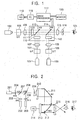
- Fig. 1 is a block diagram of such a known color moving-image holographic reproducing device.
- reference numeral 101 denotes a He-Ne laser functioning as a red light source
- reference numeral 102 denotes a YAG laser functioning as a green light source
- reference numeral 103 denotes a He-Cd laser functioning as a blue light source.
- Reference numerals 104, 105, and 106 denote spatial filters (SFs).
- Reference numerals 107, 108, 109, and 115 denote lenses.
- Reference numerals 110, 111, and 112 denote transmissive LCDs.
- Reference numerals 113 and 114 denote half mirrors (HMs).
- Reference numeral 116 denotes a slit.
- Reference numeral 117 denotes an image processor.
- Reference numeral 118 denotes a computer (PC: personal computer).
- Reference numeral 119 denotes a magneto-optical drive (MO).
- Reference numeral 120 denotes a monitor.
- Reference numeral 121 denotes an observer.
- three lasers 101, 102, and 103 are a red light source (He-Ne laser), a green light source (YAG laser), and a blue light source (He-Cd laser), respectively.
- Waveforms of the laser beams are reshaped by the spatial filters (SFs) 104, 105, and 106 and are then projected onto the LCDs 110, 111, and 112, respectively.
- SFs spatial filters
- Holograms for red, green, and blue are displayed on the three LCDs 110, 111, and 112, respectively.
- the reproduced beams of light from the holograms are combined by the half mirrors (HMs) 113 and 114 to form a color holographic image.
- the holograms displayed on the LCDs 110, 111, and 112 are created by the personal computer 118 and then delivered to the LCDs via the image processor 117.
- three holograms are prepared for three, that is, R (red), G (green), and B (blue), color light sources and the reproduced beams of light are combined to form a color holographic image.
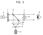
- Fig. 2 is a block diagram of another known color moving-image holographic reproducing device.
- reference numeral 201 denotes a laser functioning as a red light source
- reference numeral 202 denotes a laser functioning as a green light source
- reference numeral 203 denotes a laser functioning as a blue light source.
- Reference numerals 204, 205, and 206 denote electronic shutters (SH1, SH2, and SH3), respectively.
- Reference numerals 207, 208, and 212 denote half mirrors (HM1, HM2, and HM3), respectively.
- Reference numerals 209, 210, and 215 denote lenses (L1, L2, and L3), respectively.
- Reference numeral 211 denotes a mirror (M1).
- Reference numeral 213 denotes a reflective LCD.
- Reference numeral 214 denotes a computer (PC: personal computer).
- Reference numeral 216 denotes a reconstructed image.
- Reference numeral 217 denotes an observer.
- Beams from the three lasers (red laser, green laser, and blue laser) 201, 202, and 203 are combined into one beam by the half mirrors (HM1 and HM2) 207 and 208.
- HM1 and HM2 half mirrors
- SH1, SH2, or SH3 electronic shutter
- This beam is projected onto the reflective LCD 213 after passing through the lenses (L1 and L2) 209 and 210, the mirror (M1) 211, and the half mirror (HM3) 212.
- the computer (PC) 214 sequentially generates holograms for red, green, and blue components in synchronization with the electronic shutter 204, 205, and 206, and then displays them on the reflective LCD 213.
- R (red), G (green), and B (blue) components of the image are sequentially displayed on a single hologram by using time-multiplexing while light beams from R, G, and B light sources are synchronously projected onto the hologram.
- a color image is reconstructed by displaying the color components at a high enough time-multiplexing rate for human visual perception.
- LCD liquid crystal display
- Systems that use LCDs do not have the above-described drawbacks.
- the systems are capable of 1) reconstructing a complete three-dimensional image and 2) being completely electronically controlled.
- the LCD can be used simply by being connected to a computer. Accordingly, the LCD.provides easy handling and, therefore, the LCD is a suitable device for CGH.
- Moving-image holographic reproducing devices using LCDs were carried out by Citizen Watch Co., Ltd. and Telecommunications Advancement Organization of Japan and so on in the early 1990's, and moving images were successfully displayed.
- a high-resolution transmissive LCD which was developed for a projector and had a pixel pitch of 30 to 50 ⁇ m, was used as a display device.
- this pitch was insufficient and, therefore, a reconstructed image was too small for the naked eye to view. This result suggested that an LCD could not be used as a display device for reconstruction of a holographic image.
- LCDs having a higher resolution, about 10 ⁇ m pixel pitch, have been developed. These high-resolution LCDs are reflective LCDs used for recent practical applications instead of known transmissive LCDs.
- reflective LCDs Compared to transmissive LCDs, reflective LCDs have two main advantages for reconstruction of a holographic image.
- a reflective LCD structurally facilitates high pixel resolution. Since a reflective LCD has a control circuit on its back surface, liquid crystal elements can be closely arranged on a front surface of the reflective LCD.
- the structural advantage provides another advantage for the usability of light. That is, in a transmissive LCD, since a control circuit must be mounted on the same plane as liquid crystal elements, achieving a high aperture ratio is difficult. Consequently, the transmittance ratio is about 30% and, therefore, the reconstructed image is dark. In contrast, a reflective LCD can increase the reflectance ratio (theoretically greater than 90% is possible) and, therefore, a bright reconstructed image can be easily achieved. This is a second advantage.
- the inventor of the present invention recognized that a reflective LCD was the most suitable display for a practical holographic reproducing device and experimented on holographic reproduction with a reflective LCD.
- the experiment of the system was first conducted using a laser, which had been used for moving-image holography, as a light source for reproducing the image.
- the experimental result was disclosed in a short paper in the Journal of the Institute of Image Information and Television Engineers in May, 2000.
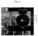
- Fig. 3 is a block diagram of a moving-image holographic reproducing device including a reflective liquid crystal display and a light-emitting diode according to a first embodiment of the present invention.
- reference numeral 1 denotes a reflective liquid crystal display (reflective LCD).
- Reference numeral 2 denotes a personal computer (PC).
- Reference numeral 3 denotes a light-emitting diode (LED).
- Reference numeral 3A denotes LED light.
- Reference numeral 4 denotes a pinhole filter.
- Reference numeral 5 denotes a collimator lens.
- Reference numeral 6 denotes a beam splitter (half mirror).
- Reference numeral 7 denotes a field lens.
- Reference numeral 8 denotes an observer.
- Reference numeral 9 denotes a reconstructed image.
- the reflective LCD 1 is, for example, the CMD8x6D available from Colorado MicroDisplay Inc.
- the CMD8 ⁇ 6D includes a small panel having a pixel pitch of 12 ⁇ m, 480 thousand (800 by 600) total number of pixels, and an absolute size of 9.6 mm by 7.2 mm.
- the LED 3 is, for example, one from the NSP series available from NICHIA Corporation.
- Wavefronts from the LED 3 are reshaped into plane waves by the pinhole filter 4 and the collimator lens 5 before the wavefronts are used.
- the other lens is the field lens 7, which closes up the reconstructed image 9 so that the reconstructed image 9 is easily viewed by the observer 8.
- a sequence of reconstructing an image is as follows:
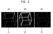
- Fig. 4 is an example of a reconstructed cube with a moving-image holographic reproducing device according to the first embodiment of the present invention.
- reference numeral 10 denotes a supporting portion of a reflective liquid crystal display (reflective LCD panel).
- Reference numeral 11 denotes a reflective LCD panel.
- Reference numeral 12 denotes a field lens.
- Reference numeral 13 denotes a cube (a reconstructed image viewed from the front).
- Reference numeral 14 denotes a direct beam of light from an LED (not shown).
- a slanting 2-cm-edge cube having 240 pixels was reconstructed in the air 1 m distant from the reflective LCD panel 11.
- the field lens 12 including the cube 13 was 5 cm in diameter.
- a bright spot 14 substantially at the center of the cube 13 was the direct light from the LED (not shown).
- the cube 13 (a reconstructed image viewed from the front) was reconstructed with diffracted light.
- a clear image was able to be reconstructed even though a laser for a light source was replaced with a light-emitting diode.
- a laser is not suitable for reference light when humans observe objects.
- the known display systems using LCDs indicate that, if a laser that should be used as a beam of light is used as divergent waves by interference fringes, even a high-power laser cannot provide sufficient intensity.
- the laser light is coherent light that disadvantageously generates speckle noise.
- a reflective LCD that can operate with LED-emitting incoherent light can provide the system with significant flexibility and cost reduction.
- Fig. 5 is an example of reconstruction using LEDs for three primary colors of light, red (R), green (G), and blue (B), in a moving-image holographic reproducing device according to the first embodiment of the present invention.
- R red
- G green
- B blue
- a direct beam of light is optically eliminated.
- a red (R) image 21, a green (G) image 22, and a blue (B) image 23 of the cube are clearly reconstructed, respectively.
- Holography is the only known technology that can record and faithfully reconstruct three-dimensional wavefronts.
- the moving three-dimensional image system using holography is considered to become an ultimate 3-D television.
- the practical application of holography is difficult.
- some predicted that real applications could be achieved in about 2020. The two main reasons are as follows:
- Holography utilizes interference and diffraction of light.
- a wavefront of an object beam is overlapped with in-phase reference beam of light, such as a laser beam, and interference fringes are then recorded on a photographic plate (hologram).
- hologram photographic plate
- To reconstruct an image only the reference beam of light is projected onto the hologram.
- the projected reference beam of light is diffracted by the interference fringes and the diffracted light faithfully reconstructs the wavefront of the object light.
- the size of the viewing zone depends on the pixel pitch of a display device.
- Optical films such as photosensitive silver salt films, have an image resolution between 0.1 and 1 ⁇ m, which corresponds to the pixel pitch, and a viewing zone size of greater than or equal to 40°. Therefore, the optical films provide sufficient capability of reconstructing a three-dimensional image. In fact, for still images, many superior holographic works have been created. However, for moving images, the hologram must be successively updated. The development of such a high-resolution display device that controls the large amount of data is difficult.
- LCD liquid crystal display
- This pitch is yet an order of magnitude greater than that of an optical film.
- a holographic reconstruction experiment using one of these LCD panels exhibited a superior result such that an image of about 3 cm is clearly reconstructed and a light-emitting diode (LED) can be used as a reference light source instead of a laser (refer to the above-described first embodiment).
- LED light-emitting diode
- the display device has a sufficiently high resolution, a problem of a computational processing system increases.
- the above-described two problems are dependent on each other; a high-resolution display device necessarily increases the amount of information.
- the problem of moving-image holography finally results in the problem of information processing speed.
- this amounts to 100 million pixels.
- computational power 1000 to 10000 times higher than that of a current supercomputer is required.
- the inventor of the present invention has suggested that a dedicated computer system is considerably advantageous for the computational processing of holography (refer to the above-described References 3, 4, and 5).
- a real-time moving-image holographic reproducing device (3-D television) is proposed in which a high-speed parallel distributed processing system dedicated for holography is combined with a high-resolution reflective LCD. That is, in the dedicated high-speed parallel distributed processing system (computer system) and a display system, a dedicated hardware arithmetic circuit executes the parallel distributed processing.
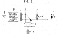
- Fig. 6 is a system block diagram of a moving-image holographic reproducing device according to the second embodiment of the present invention. Elements identical to those illustrated and described in relation to the first embodiment are designated by like reference numerals and the descriptions are omitted.
- a dedicated high-speed parallel distributed processing system 31 is disposed between a PC (host computer) 2 and the high-resolution reflective liquid crystal display (LCD panel) 1.
- Interference fringes of a hologram can be generated by computation of a computer.
- the hologram is referred to as a computer-generated hologram (CGH), which is used in this embodiment.
- CGH computer-generated hologram
- a computer system converts three-dimensional computer graphics to the CGHs at high speed and then successively displays them on a display system.
- the displayed holograms are reconstructed in the air at a position of the field lens as moving three-dimensional images by a reproducing optical system.
- This embodiment is characterized in that holography moving images are reconstructed by a high-speed parallel distributed processing of the computer system and the display system in real time.
- the reproducing optical system adopts the technology disclosed in the above-described first embodiment.
- the display area of 10 cm by 10 cm is composed of a plurality of commercially available LCD panels having a 10 ⁇ m pitch, that is, 1000 by 1000 pixels, and an effective display area of 1 cm by 1 cm.
- the size S of a reconstructed image is determined by diffraction angle ⁇ and the reconstruction position, namely, the distance L between the LCD panel and the field lens.
- the diffraction angle for a 10 ⁇ m pitch is about 3°.
- the LCD panels do not need to be closely arranged.
- An image can be reconstructed even with about sixteen LCD panels evenly arranged as shown in Fig. 7 so as to overlap each reconstruction area at the reconstruction position. This is due to the fact that holographic data has high redundancy.
- the display size is, in principal, scalable.
- ⁇ represents a point on a hologram
- j represents a point that constitutes an object
- Aj is the intensity of light of the object point
- R ⁇ j is a distance between the hologram point and the object point
- k is the wave number of a reference beam.
- M is the total number of the object points.
- Eq. (2) itself corresponds to about 30 arithmetic operations.
- N the amount of computation for a plate is estimated to be 30MN.
- a computational power of about 10 3 MN floating point operations per second (flops) is required.
- a computational power of 10 peta (P: 10 15 ) flops is required.
- a computational power of 10 peta (P: 10 15 ) flops is required.
- a computational power of Pflops is required. This is 1000 times faster than current supercomputers whose computational power has recently reached a speed of tera (T: 10 12 ) flops.
- Fig. 8 is a block diagram of a parallel distributed system including the dedicated chip.
- reference numeral 31 denotes a dedicated high-speed parallel distributed processing system (dedicated computer).
- Reference numeral 32 denotes a memory for storing object data.
- Reference numerals 33A, ..., 33N denote dedicated chips and reference numeral 34 denotes a data communication chip.
- An LCD panel 1 is divided into several areas and the dedicated chips 33A to 33N generate data for the respective areas.
- a problem of parallel computation is a communication cost. In this embodiment, this problem does not occur.
- the flow of data is unidirectional.
- a host computer 2 only needs to transmit object point data to the memory 32 for storing object data in the dedicated high-speed parallel distributed processing system (dedicated computer) 31 via the data communication chip 34. That is, the amount of data communication has no relation to the size of the hologram.
- the dedicated chips (dedicated LSIs) 33A, ..., 33N reference the object data at the same time, calculate interference fringes for the assigned points on the hologram, and then directly deliver the results to the display 1.
- the communications do not cross at all, and the data are distributedly processed. Accordingly, the communications do not constitute a bottleneck.
- This transfer speed is only determined by the number of pixels of the image and does not depend on the size of the hologram. That is, in this embodiment, although the numbers of the dedicated chips and the units of the LCD panel increase, the communication load does not increase. Consequently, a hologram surface of any size can be achieved.
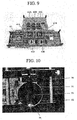
- Fig. 9 is an external view of a specific dedicated high-speed parallel distributed processing system of the moving-image holographic reproducing device according to the second embodiment of the present invention.
- reference numerals 41A and 41B denote two dedicated holographic computing chips
- reference numerals 42A to 42E denote five memories for storing object data
- reference numeral 43 denotes a data communication chip.
- Fig. 10 is an example of a reconstructed dice by the moving-image holographic reproducing device according to the second embodiment of the present invention.
- reference numeral 50 denotes a supporting portion of a lens holder of a field lens
- reference numeral 51 denotes the reflective LCD panel
- reference numeral 52 denotes a field lens
- reference numeral 53 denotes a dice (a reconstructed image viewed from the front).
- Reference numeral 54 denotes a direct beam of light from an LED (not shown).
- an image reconstructing experiment was conducted with a test device including the two dedicated chips 41A and 41B and two LCD panels, as a minimum configuration of the embodiment.
- the dedicated chips 41A and 41B were manufactured by using the EP20K300EQC240-1, a 300,000-gate programmable logic device (PLD), from Altera Corporation. Each chip included 30 circuits, each calculating the above-described equation (2). A board including the two chips was manufactured.
- the LCD panel 51 was made from the DILA-SX070, a high-resolution reflective LCD, available from Victor Company of Japan, Limited. This panel had pixel pitches of 10.4 ⁇ m by 10.4 ⁇ m, 1400 by 1050 pixels, and an effective display area of 14.6 mm by 10.9 mm. Two of the panels were used. A moving image was reconstructed by this system using an optical reconstruction unit with an LED as a reference light source.
- Fig. 10 shows an example of the experiment.
- the moving image 53 of a rotating 3-cm-edge dice made from 2600 pixels is presented.
- a color moving-image holographic reproducing device according to another embodiment of the present invention will be described below.
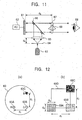
- Fig. 11 is a block diagram of the color moving-image holographic reproducing device according to the embodiment of the present invention.
- reference numeral 61 denotes a reflective liquid crystal display (reflective LCD).
- Reference numeral 62 denotes a computer (PC: personal computer).
- Reference numeral 63 denotes light-emitting diodes (LEDs), which are R, G, and B light sources.
- Reference numeral 64 denotes pinhole filters.
- Reference numeral 65 denotes a collimator lens.
- Reference numeral 66 denotes a beam splitter (half mirror).
- Reference numeral 67 denotes a field lens.
- Reference numerals 68 and 69 denote an observer and a reconstructed image, respectively.
- a hologram generated by the computer (PC) 62 is displayed on the reflective LCD 61, which is irradiated with parallel light emitted from the LED 63 as reference light to reconstruct a moving three-dimensional image.
- a distance between the pinhole filter 64 and the collimator lens 65 is d 2 (300 mm) and the image 69 is reconstructed in the air at a position a distance d 3 (1000 mm) away from the surface of the LCD 1.
- reference light sources that is, a red (R) light source 63A, a green (G) light source 63B, and a blue (B) light source 63C are arranged in proximity to each other, as shown in Fig. 12(a).
- the R, G, and B light sources 63 emit light at the same time instead of emitting light in a time-multiplexing manner.
- the pinhole filter 64 is prepared for each of the R, G, and B light sources 63.
- This arrangement shifts optical axes of the three colors from each other.
- the color moving-image holographic reproducing device according to the present invention makes active use of the shift.
- Each beam of the R, G, and B light is reshaped into parallel light by the collimator lens 65. Since the R, G, and B light sources functioning as reference light sources are placed at different positions, each beam of parallel light is incident on the reflective LCD 61 at a different angle. Therefore, direct reflected light at the reconstruction position, which is a distance d 3 (1000 mm) from the reflective LCD 61, is shown in Fig. 12(b).
- the size of rectangular regions 69A, 69B, and 69C shown in Fig. 12(b) is d 5 (14.6 mm) by d 6 (10.4 mm), which is the same size as that of the LCD panel used in the embodiment.
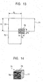
- a color graphic is divided into R, G, and B components and each component is drawn in the corresponding region shown in Fig. 13, the color components are combined at a hologram reconstruction area 69D shown in Fig. 12(b) and an original color graphic is reconstructed.
- a rectangular region 70 of d 5 (14.6 mm) by d 6 (10.4 mm) at a center of Fig. 13 is an area overlapping with the direct light reflected from the LCD 61, the device does not draw the graphic in this region.
- a color is represented by a combination of the R, G, and B components, thus considerably facilitating the dividing operation of the color.
- reference numerals 71, 72, and 73 denote regions for the red component, green component, and blue component, respectively.
- holography reconstruction of a cube 75 having three colors, red 76, green 77, and blue 78, will be discussed.
- Fig. 15(a) the cube is redrawn in each color component region 71, 72, or 73, thus resulting in the example shown in Fig. 15(a). If this is reconstructed with a plain color (for example, red), the image is, of course, reconstructed as shown in Fig. 15(b).
- reference numeral 80 denotes the region for the direct light
- reference numerals 81, 82, and 83 denote the regions for the divided color components.
- FIG. 15(a) A reconstruction of the hologram shown in Fig. 15(a) with the RGB reference light sources shown in Fig. 12(a) will be discussed next. Since each RGB light source produces the reconstructed image shown in Fig. 15(b), the entire reconstructed image is shown in Fig. 16. That is, as can be seen, the original color cube 94 (corresponding to the cube 75) is reconstructed in an area surrounded by the direct RGB light (an R direct light region 91, a G direct light region 92, and a B direct light region 93). Reference numerals 95, 96, 97, 98, 99, and 100 denote the regions for the divided color components.
- Fig. 17 shows an example of an actual reconstruction, in which images of characters R, G, and B were displayed in respective color regions and the hologram was then reconstructed. Although the blue direct light moved outside the field lens and, therefore, did not exist in the drawing, it was confirmed that a color image was actually reconstructed in the area surrounded by each beam of direct light.
- the size of a color reconstruction area is determined in accordance with the mutual ratios of the distance (d 1 ) between the LEDs, the distance (d 2 ) between the pinhole filter and the collimator lens, and the distance (d 3 ) between the reflective liquid crystal display and the field lens that produces a reconstructed image.
- the present invention provides the following advantages:
- the moving-image holographic reproducing device and the color moving-image holographic reproducing device are expected to be applied, in particular, to moving three-dimensional image systems.
Landscapes
- Physics & Mathematics (AREA)
- General Physics & Mathematics (AREA)
- Holo Graphy (AREA)
- Testing, Inspecting, Measuring Of Stereoscopic Televisions And Televisions (AREA)
Abstract
A moving-image holographic reproducing device that
includes a reflective liquid crystal display and further a
light-emitting diode functioning as a light source and that
is capable of reproducing a high-resolution image in a
simple way is provided. Also, a color moving-image
holographic reproducing device that is capable of
reproducing a color holographic image by a significantly
simplified structure using a single plate hologram without
the need for time-multiplexing is provided.
The moving-image holographic reproducing device
includes a computer for creating a hologram from three-dimensional
coordinate data, a reflective liquid crystal
display for displaying the hologram, a half mirror for
projecting the displayed hologram, and a light-emitting
diode, wherein a reconstructed three-dimensional image is
displayed by illuminating the half mirror with light emitted
from the light-emitting diode.
Manipulating a sufficiently large size three-dimensional
holographic image in real time requires
computational power one thousand to ten thousand times
higher than that of current supercomputers. According to
the present invention, such an amount of information can be
processed at high speed by dedicated hardware in a highly
parallel and distributed manner.
Description
The present invention generally relates to a moving-image
holographic reproducing device and a color moving-image
holographic reproducing device. More particularly,
the present invention relates to a moving-image holographic
reproducing device including a reflective liquid crystal
display and light-emitting diodes and to a moving-image
holographic reproducing device including dedicated high-speed
parallel processing hardware for holographic
computation and a reflective liquid crystal display, and
also to a color moving-image holographic reproducing device
using three primary-color reference light sources and a
single-plate hologram.
In holography, wavefronts of an object beam are
overlapped by a reference beam of light in phase and are
then recorded on a hologram as interference fringes. To
reproduce an image, the wavefronts of the object beam are
faithfully reconstructed by illuminating the hologram with
the reference beam of light. The hologram can be created by
a computer. This hologram is referred to as "a computer
generated hologram (CGH)". Therefore, theoretically, if
data resulting from a numerical simulation is converted into
a hologram by computation and is holographically
reconstructed, a three-dimensional image can be visualized.
Furthermore, by consecutively updating the data, a moving
three-dimensional image can be observed.
This process requires a device capable of successively
updating the hologram data. Unfortunately, known devices
cannot record interference fringes of a hologram
sufficiently and, therefore, satisfactory moving images
cannot be provided.
The idea of displaying a moving holographic image was
first researched at the Massachusetts Institute of
Technology (MIT) in 1989. The research group of MIT used an
acousto-optical modulator (AOM) as a display device. A
reconstructed image was enlarged by a mechanical and optical
setup including a polygon mirror. In 1995, an image having
a size of about 10 cm was successfully reconstructed. This
system exhibited a sophisticated and outstanding idea in
that a three-dimensional image was electronically produced
in a technology environment at the time.
As shown.in the above-described references, to achieve
color moving-image holography, the following two methods
have been proposed.
Fig. 1 is a block diagram of such a known color moving-image
holographic reproducing device. In this drawing,
reference numeral 101 denotes a He-Ne laser functioning as a
red light source, reference numeral 102 denotes a YAG laser
functioning as a green light source, and reference numeral
103 denotes a He-Cd laser functioning as a blue light source.
Reference numerals 104, 105, and 106 denote spatial filters
(SFs). Reference numerals 107, 108, 109, and 115 denote
lenses. Reference numerals 110, 111, and 112 denote
transmissive LCDs. Reference numerals 113 and 114 denote
half mirrors (HMs). Reference numeral 116 denotes a slit.
Reference numeral 117 denotes an image processor. Reference
numeral 118 denotes a computer (PC: personal computer).
Reference numeral 119 denotes a magneto-optical drive (MO).
Reference numeral 120 denotes a monitor. Reference numeral
121 denotes an observer.
As shown in Fig. 1, three lasers 101, 102, and 103 are
a red light source (He-Ne laser), a green light source (YAG
laser), and a blue light source (He-Cd laser), respectively.
Waveforms of the laser beams are reshaped by the spatial
filters (SFs) 104, 105, and 106 and are then projected onto
the LCDs 110, 111, and 112, respectively.
Holograms for red, green, and blue are displayed on the
three LCDs 110, 111, and 112, respectively. The reproduced
beams of light from the holograms are combined by the half
mirrors (HMs) 113 and 114 to form a color holographic image.
The holograms displayed on the LCDs 110, 111, and 112 are
created by the personal computer 118 and then delivered to
the LCDs via the image processor 117.
As described above, in the known devices, three
holograms are prepared for three, that is, R (red), G
(green), and B (blue), color light sources and the
reproduced beams of light are combined to form a color
holographic image.
Fig. 2 is a block diagram of another known color
moving-image holographic reproducing device.
In this drawing, reference numeral 201 denotes a laser
functioning as a red light source, reference numeral 202
denotes a laser functioning as a green light source, and
reference numeral 203 denotes a laser functioning as a blue
light source. Reference numerals 204, 205, and 206 denote
electronic shutters (SH1, SH2, and SH3), respectively.
Reference numerals 207, 208, and 212 denote half mirrors
(HM1, HM2, and HM3), respectively. Reference numerals 209,
210, and 215 denote lenses (L1, L2, and L3), respectively.
Reference numeral 211 denotes a mirror (M1). Reference
numeral 213 denotes a reflective LCD. Reference numeral 214
denotes a computer (PC: personal computer). Reference
numeral 216 denotes a reconstructed image. Reference
numeral 217 denotes an observer.
Beams from the three lasers (red laser, green laser,
and blue laser) 201, 202, and 203 are combined into one beam
by the half mirrors (HM1 and HM2) 207 and 208. At that time,
since each beam is turned on and off in rapid succession by
the corresponding electronic shutter (SH1, SH2, or SH3) 204,
205, or 206, the combined beam is projected in a time-multiplexing
sequence of red, green, and blue.
This beam is projected onto the reflective LCD 213
after passing through the lenses (L1 and L2) 209 and 210,
the mirror (M1) 211, and the half mirror (HM3) 212. The
computer (PC) 214 sequentially generates holograms for red,
green, and blue components in synchronization with the
electronic shutter 204, 205, and 206, and then displays them
on the reflective LCD 213.
Thus, in the known devices, R (red), G (green), and B
(blue) components of the image are sequentially displayed on
a single hologram by using time-multiplexing while light
beams from R, G, and B light sources are synchronously
projected onto the hologram. A color image is reconstructed
by displaying the color components at a high enough time-multiplexing
rate for human visual perception.
Unfortunately,
In contrast, a liquid crystal display (LCD) is commonly
used as an electronically controlled display device.
Systems that use LCDs do not have the above-described
drawbacks. The systems are capable of 1) reconstructing a
complete three-dimensional image and 2) being completely
electronically controlled. In addition, the LCD can be used
simply by being connected to a computer. Accordingly, the
LCD.provides easy handling and, therefore, the LCD is a
suitable device for CGH.
Moving-image holographic reproducing devices using LCDs
were carried out by Citizen Watch Co., Ltd. and
Telecommunications Advancement Organization of Japan and so
on in the early 1990's, and moving images were successfully
displayed. At that time, a high-resolution transmissive LCD,
which was developed for a projector and had a pixel pitch of
30 to 50 µm, was used as a display device. However, to
reconstruct a holographic image, this pitch was insufficient
and, therefore, a reconstructed image was too small for the
naked eye to view. This result suggested that an LCD could
not be used as a display device for reconstruction of a
holographic image.
Recently, LCDs having a higher resolution, about 10 µm
pixel pitch, have been developed. These high-resolution
LCDs are reflective LCDs used for recent practical
applications instead of known transmissive LCDs.
Compared to transmissive LCDs, reflective LCDs have two
main advantages for reconstruction of a holographic image.
First, a reflective LCD structurally facilitates high
pixel resolution. Since a reflective LCD has a control
circuit on its back surface, liquid crystal elements can be
closely arranged on a front surface of the reflective LCD.
Additionally, the structural advantage provides another
advantage for the usability of light. That is, in a
transmissive LCD, since a control circuit must be mounted on
the same plane as liquid crystal elements, achieving a high
aperture ratio is difficult. Consequently, the
transmittance ratio is about 30% and, therefore, the
reconstructed image is dark. In contrast, a reflective LCD
can increase the reflectance ratio (theoretically greater
than 90% is possible) and, therefore, a bright reconstructed
image can be easily achieved. This is a second advantage.
Accordingly, the inventor of the present invention
recognized that a reflective LCD was the most suitable
display for a practical holographic reproducing device and
experimented on holographic reproduction with a reflective
LCD.
The experiment of the system was first conducted using
a laser, which had been used for moving-image holography, as
a light source for reproducing the image. The experimental
result was disclosed in a short paper in the Journal of the
Institute of Image Information and Television Engineers in
May, 2000.
Thus, the structures of the known color moving-image
holographic reproducing devices are complicated and,
therefore, the cost is disadvantageously increased.
Accordingly, it is an object of the present invention
to provide a simple color moving-image holographic
reproducing device that can reconstruct a high-resolution
image by using a reflective liquid crystal display and
further using a light-emitting diode as a reproducing light
source.
It is another object of the present invention to
provide a significantly simplified color moving-image
holographic reproducing device that can achieve color
holography by using a single-plate hologram without the need
for time-multiplexing.
According to the present invention,
Embodiments of the present invention will now be
described with reference to the accompanying drawings.
Fig. 3 is a block diagram of a moving-image holographic
reproducing device including a reflective liquid crystal
display and a light-emitting diode according to a first
embodiment of the present invention.
In the drawing, reference numeral 1 denotes a
reflective liquid crystal display (reflective LCD).
Reference numeral 2 denotes a personal computer (PC).
Reference numeral 3 denotes a light-emitting diode (LED).
Reference numeral 3A denotes LED light. Reference numeral 4
denotes a pinhole filter. Reference numeral 5 denotes a
collimator lens. Reference numeral 6 denotes a beam
splitter (half mirror). Reference numeral 7 denotes a field
lens. Reference numeral 8 denotes an observer. Reference
numeral 9 denotes a reconstructed image.
As can be seen, this moving-image holographic
reproducing device is very simple. In this device, the
reflective LCD 1 is, for example, the CMD8x6D available from
Colorado MicroDisplay Inc.. The CMD8×6D includes a small
panel having a pixel pitch of 12 µm, 480 thousand (800 by
600) total number of pixels, and an absolute size of 9.6 mm
by 7.2 mm. The LED 3 is, for example, one from the NSP
series available from NICHIA Corporation.
Wavefronts from the LED 3 are reshaped into plane waves
by the pinhole filter 4 and the collimator lens 5 before the
wavefronts are used. The other lens is the field lens 7,
which closes up the reconstructed image 9 so that the
reconstructed image 9 is easily viewed by the observer 8.
A sequence of reconstructing an image is as follows:
The experimental results on a hologram reproduced with
the moving-image holographic reproducing device including
the reflective LCD and the light-emitting diode according to
the present invention will be described below.
Fig. 4 is an example of a reconstructed cube with a
moving-image holographic reproducing device according to the
first embodiment of the present invention.
In the drawing, reference numeral 10 denotes a
supporting portion of a reflective liquid crystal display
(reflective LCD panel). Reference numeral 11 denotes a
reflective LCD panel. Reference numeral 12 denotes a field
lens. Reference numeral 13 denotes a cube (a reconstructed
image viewed from the front). Reference numeral 14 denotes
a direct beam of light from an LED (not shown).
In this embodiment, a slanting 2-cm-edge cube having
240 pixels was reconstructed in the air 1 m distant from the
reflective LCD panel 11. Herein, the field lens 12
including the cube 13 was 5 cm in diameter. A bright spot
14 substantially at the center of the cube 13 was the direct
light from the LED (not shown). The cube 13 (a
reconstructed image viewed from the front) was reconstructed
with diffracted light.
Viewing direct beams of laser light is dangerous for
the human eye, whereas LED light is not harmful. To show
the contrast, the direct light and the diffracted light are
shown in the drawing. Of course, cutting off the direct
light is technically easy. As shown in Fig. 4, the
reconstructed image 13 can be clearly viewed under room
lighting.
Thus, according to the present invention, a clear image
was able to be reconstructed even though a laser for a light
source was replaced with a light-emitting diode.
Additionally, eliminating the need for a laser can
significantly reduce the size of the system.
Furthermore, a laser is not suitable for reference
light when humans observe objects. The known display
systems using LCDs indicate that, if a laser that should be
used as a beam of light is used as divergent waves by
interference fringes, even a high-power laser cannot provide
sufficient intensity. Also, the laser light is coherent
light that disadvantageously generates speckle noise.
As described above, a reflective LCD that can operate
with LED-emitting incoherent light can provide the system
with significant flexibility and cost reduction.
Fig. 5 is an example of reconstruction using LEDs for
three primary colors of light, red (R), green (G), and blue
(B), in a moving-image holographic reproducing device
according to the first embodiment of the present invention.
In the drawing, a direct beam of light is optically
eliminated.
In Figs. 5(a), 5(b), and 5(c), a red (R) image 21, a
green (G) image 22, and a blue (B) image 23 of the cube are
clearly reconstructed, respectively.
This result indicates that each of the red (R), green
(G), and blue (B) images is clearly reconstructed, as shown
in the drawing. This result also indicates that a color
image is easily reconstructed by producing red (R), green
(G), and blue (B) images and combining them. Such an image
producing system including a combination of a reflective LCD
and an LED is identical to current two-dimensional display
devices, such as televisions, and, therefore, a moving
three-dimensional image system (3-D television) can be
achieved as an extension of current technologies.
A second embodiment of the present invention will be
described next.
Holography is the only known technology that can record
and faithfully reconstruct three-dimensional wavefronts.
The moving three-dimensional image system using holography
is considered to become an ultimate 3-D television. However,
the practical application of holography is difficult. At
the beginning of the 21st century, some predicted that real
applications could be achieved in about 2020. The two main
reasons are as follows:
Holography utilizes interference and diffraction of
light. A wavefront of an object beam is overlapped with in-phase
reference beam of light, such as a laser beam, and
interference fringes are then recorded on a photographic
plate (hologram). To reconstruct an image, only the
reference beam of light is projected onto the hologram. The
projected reference beam of light is diffracted by the
interference fringes and the diffracted light faithfully
reconstructs the wavefront of the object light.
Since the diffracted light is used to reconstruct the
wavefront, the size of the viewing zone depends on the pixel
pitch of a display device. Optical films, such as
photosensitive silver salt films, have an image resolution
between 0.1 and 1 µm, which corresponds to the pixel pitch,
and a viewing zone size of greater than or equal to 40°.
Therefore, the optical films provide sufficient capability
of reconstructing a three-dimensional image. In fact, for
still images, many superior holographic works have been
created. However, for moving images, the hologram must be
successively updated. The development of such a high-resolution
display device that controls the large amount of
data is difficult.
Only recently, high-resolution reflective liquid
crystal display (LCD) panels having a pixel pitch of 10 µm
have become commercially available. This pitch is yet an
order of magnitude greater than that of an optical film.
However, a holographic reconstruction experiment using one
of these LCD panels exhibited a superior result such that an
image of about 3 cm is clearly reconstructed and a light-emitting
diode (LED) can be used as a reference light source
instead of a laser (refer to the above-described first
embodiment). The resolution of reflective LCDs has been
growing year by year and is expected to grow even further in
the future.
As the display device has a sufficiently high
resolution, a problem of a computational processing system
increases. The above-described two problems are dependent
on each other; a high-resolution display device necessarily
increases the amount of information.
Accordingly, the problem of moving-image holography
finally results in the problem of information processing
speed. For example, for a 10-by-10-cm effective area
containing pixels having a pitch of 10 µm, this amounts to
100 million pixels. To drive the pixels at the video rate,
computational power 1000 to 10000 times higher than that of
a current supercomputer is required. For this problem, the
inventor of the present invention has suggested that a
dedicated computer system is considerably advantageous for
the computational processing of holography (refer to the
above-described References 3, 4, and 5).
In this embodiment, by using the above-described
research result, a real-time moving-image holographic
reproducing device (3-D television) is proposed in which a
high-speed parallel distributed processing system dedicated
for holography is combined with a high-resolution reflective
LCD. That is, in the dedicated high-speed parallel
distributed processing system (computer system) and a
display system, a dedicated hardware arithmetic circuit
executes the parallel distributed processing.
Fig. 6 is a system block diagram of a moving-image
holographic reproducing device according to the second
embodiment of the present invention. Elements identical to
those illustrated and described in relation to the first
embodiment are designated by like reference numerals and the
descriptions are omitted.
In this embodiment, a dedicated high-speed parallel
distributed processing system 31 is disposed between a PC
(host computer) 2 and the high-resolution reflective liquid
crystal display (LCD panel) 1.
The dedicated high-speed parallel distributed
processing system will be described below.
Interference fringes of a hologram can be generated by
computation of a computer. The hologram is referred to as a
computer-generated hologram (CGH), which is used in this
embodiment.
A computer system converts three-dimensional computer
graphics to the CGHs at high speed and then successively
displays them on a display system. The displayed holograms
are reconstructed in the air at a position of the field lens
as moving three-dimensional images by a reproducing optical
system. This embodiment is characterized in that holography
moving images are reconstructed by a high-speed parallel
distributed processing of the computer system and the
display system in real time. The reproducing optical system
adopts the technology disclosed in the above-described first
embodiment.
The display system of this embodiment will be described
next.
At this time, a high-resolution, large-screen LCD for
reconstruction of a holographic image of sufficient size is
not available (at least not commercially available). The
display system used in this embodiment is first described
below.
For example, to reconstruct an image larger than 10 cm
with an LCD having 10 µm pitch, a display area of about 10
cm by 10 cm is required. Herein, the display area of 10 cm
by 10 cm is composed of a plurality of commercially
available LCD panels having a 10 µm pitch, that is, 1000 by
1000 pixels, and an effective display area of 1 cm by 1 cm.
Since a holographic image is reconstructed by using
diffraction of light, the size S of a reconstructed image is
determined by diffraction angle and the reconstruction
position, namely, the distance L between the LCD panel and
the field lens. The size S is given by the following
equation: S=Lsin. The diffraction angle for a 10 µm pitch
is about 3°. The reconstruction position can be freely
determined by computation. For example, if L=1 m, then a
reconstruction area having a size of 5 cm is achieved.
Accordingly, the LCD panels do not need to be closely
arranged. An image can be reconstructed even with about
sixteen LCD panels evenly arranged as shown in Fig. 7 so as
to overlap each reconstruction area at the reconstruction
position. This is due to the fact that holographic data has
high redundancy. Of course, as the number of pixels
increases, the quality of the image increases. In this
embodiment, the display size is, in principal, scalable.
The high-speed parallel distributed processing system
will be described below.
Interference fringes of a hologram can be given by the
following equations:

αj = (Aj /Rαj ) c o s (kRαj )
The computation is performed for discrete points, where
α represents a point on a hologram, j represents a point
that constitutes an object, Aj is the intensity of light of
the object point, Rαj is a distance between the hologram
point and the object point, and k is the wave number of a
reference beam. M is the total number of the object points.
To calculate a value Iα for a point on the hologram, Eq. (2)
must be calculated M times.
Eq. (2) itself corresponds to about 30 arithmetic
operations. When the pixel count of the hologram is N, the
amount of computation for a plate is estimated to be 30MN.
To generate 30 plates per second, a computational power of
about 103MN floating point operations per second (flops) is
required. For example, to reconstruct a moving image of an
object created with 100 thousand points (M=105) by using a
10-by-10-cm LCD having a pitch of 10 µm (total number of
pixels: 100 million, i.e., N=108), a computational power of
10 peta (P: 1015) flops is required. Even for the 16-million-pixel
display area of the example shown in Fig. 4, a
computational power of Pflops is required. This is 1000
times faster than current supercomputers whose computational
power has recently reached a speed of tera (T: 1012) flops.
In terms of speeding-up CGH, its algorithm has been
improved; a method by using difference calculus or
recurrence formula is proposed (refer to the above-described
References 6 and 7). These methods achieve dozens of times
speed-up compared to a direct computation of the above-described
equation (2).
However, more significant speed-up is required for
practical applications. Researchers in a laboratory of the
inventor of the present invention have been researching the
speed-up of the processing by hardware for ten years. The
research results suggest that holographic information
processing can be quite fast by using dedicated hardware.
The reasons are the following three:
The researchers in the laboratory of the inventor of
the present invention have developed a hardware-oriented
algorithm that can compute the above-described equation (2)
without the use of multiplications, which increase the size
of a circuit (refer to the above-described References 1 and
2). In the embodiment, this algorithm is used.
An actual circuit design using this algorithm reduced
the scale of the circuit for the above-described equation
(2) to 10 thousand gates. A dedicated chip was developed by
connecting a plurality of the circuits in parallel. At
present, the largest LSI has more than 10 million gates.
Using this LSI allows 1000 circuits to be integrated onto
the single chip. If this dedicated LSI operates at 1 GHz,
the above-described equation (2) is repeated trillion (1012)
times per second. This processing speed is 30 times faster
than that of a supercomputer.
Fifty of the dedicated LSIs operating in parallel allow
a real-time reconstruction of moving three-dimensional
images by the hologram shown in Fig. 7. If the number of
pixels of the image is limited to about 10 thousand (M=104),
five of the LSIs are sufficient. This is a practical
estimation and indicates that the high-speed parallel
distributed processing system (dedicated computer system) is
extremely effective for the moving image holography.
Fig. 8 is a block diagram of a parallel distributed
system including the dedicated chip.
In the drawing, reference numeral 31 denotes a
dedicated high-speed parallel distributed processing system
(dedicated computer). Reference numeral 32 denotes a memory
for storing object data. Reference numerals 33A, ..., 33N
denote dedicated chips and reference numeral 34 denotes a
data communication chip.
An LCD panel 1 is divided into several areas and the
dedicated chips 33A to 33N generate data for the respective
areas. In general, a problem of parallel computation is a
communication cost. In this embodiment, this problem does
not occur. As indicated by arrows shown in Fig. 8, the flow
of data is unidirectional. In addition, a host computer 2
only needs to transmit object point data to the memory 32
for storing object data in the dedicated high-speed parallel
distributed processing system (dedicated computer) 31 via
the data communication chip 34. That is, the amount of data
communication has no relation to the size of the hologram.
In the dedicated high-speed parallel distributed
processing system 31, the dedicated chips (dedicated LSIs)
33A, ..., 33N reference the object data at the same time,
calculate interference fringes for the assigned points on
the hologram, and then directly deliver the results to the
display 1. The communications do not cross at all, and the
data are distributedly processed. Accordingly, the
communications do not constitute a bottleneck. The amount
of data for each communication path is independent of the
system size and remains constant at all times. For example,
when an image having 100 thousand points is processed by the
above-described chip that repeats the above-described
equation (2) one trillion times per second, the required
transfer speed is as low as about 10 MByte/sec (1012/105=10M).
This transfer speed is only determined by the number of
pixels of the image and does not depend on the size of the
hologram. That is, in this embodiment, although the numbers
of the dedicated chips and the units of the LCD panel
increase, the communication load does not increase.
Consequently, a hologram surface of any size can be achieved.
Fig. 9 is an external view of a specific dedicated
high-speed parallel distributed processing system of the
moving-image holographic reproducing device according to the
second embodiment of the present invention. In the drawing,
reference numerals 41A and 41B denote two dedicated
holographic computing chips, reference numerals 42A to 42E
denote five memories for storing object data, and reference
numeral 43 denotes a data communication chip.
Fig. 10 is an example of a reconstructed dice by the
moving-image holographic reproducing device according to the
second embodiment of the present invention. In the drawing,
reference numeral 50 denotes a supporting portion of a lens
holder of a field lens, reference numeral 51 denotes the
reflective LCD panel, reference numeral 52 denotes a field
lens, and reference numeral 53 denotes a dice (a
reconstructed image viewed from the front). Reference
numeral 54 denotes a direct beam of light from an LED (not
shown).
As shown in the examples, an image reconstructing
experiment was conducted with a test device including the
two dedicated chips 41A and 41B and two LCD panels, as a
minimum configuration of the embodiment. The dedicated
chips 41A and 41B were manufactured by using the
EP20K300EQC240-1, a 300,000-gate programmable logic device
(PLD), from Altera Corporation. Each chip included 30
circuits, each calculating the above-described equation (2).
A board including the two chips was manufactured.
The LCD panel 51 was made from the DILA-SX070, a high-resolution
reflective LCD, available from Victor Company of
Japan, Limited. This panel had pixel pitches of 10.4 µm by
10.4 µm, 1400 by 1050 pixels, and an effective display area
of 14.6 mm by 10.9 mm. Two of the panels were used. A
moving image was reconstructed by this system using an
optical reconstruction unit with an LED as a reference light
source.
Fig. 10 shows an example of the experiment. The moving
image 53 of a rotating 3-cm-edge dice made from 2600 pixels
is presented.
The above-described configuration allows the following:
These features allow a real-time moving three-dimensional
image holographic system to be achieved.
A color moving-image holographic reproducing device,
according to another embodiment of the present invention
will be described below.
Fig. 11 is a block diagram of the color moving-image
holographic reproducing device according to the embodiment
of the present invention.
In the drawing, reference numeral 61 denotes a
reflective liquid crystal display (reflective LCD).
Reference numeral 62 denotes a computer (PC: personal
computer). Reference numeral 63 denotes light-emitting
diodes (LEDs), which are R, G, and B light sources.
Reference numeral 64 denotes pinhole filters. Reference
numeral 65 denotes a collimator lens. Reference numeral 66
denotes a beam splitter (half mirror). Reference numeral 67
denotes a field lens. Reference numerals 68 and 69 denote
an observer and a reconstructed image, respectively.
In this system, a hologram generated by the computer
(PC) 62 is displayed on the reflective LCD 61, which is
irradiated with parallel light emitted from the LED 63 as
reference light to reconstruct a moving three-dimensional
image. A distance between the pinhole filter 64 and the
collimator lens 65 is d2 (300 mm) and the image 69 is
reconstructed in the air at a position a distance d3 (1000
mm) away from the surface of the LCD 1.
The main difference from the known technology described
in (1) and (2) is that reference light sources, that is, a
red (R) light source 63A, a green (G) light source 63B, and
a blue (B) light source 63C are arranged in proximity to
each other, as shown in Fig. 12(a). The R, G, and B light
sources 63 emit light at the same time instead of emitting
light in a time-multiplexing manner. The pinhole filter 64
is prepared for each of the R, G, and B light sources 63.
This arrangement shifts optical axes of the three
colors from each other. The color moving-image holographic
reproducing device according to the present invention makes
active use of the shift.
Each beam of the R, G, and B light is reshaped into
parallel light by the collimator lens 65. Since the R, G,
and B light sources functioning as reference light sources
are placed at different positions, each beam of parallel
light is incident on the reflective LCD 61 at a different
angle. Therefore, direct reflected light at the
reconstruction position, which is a distance d3 (1000 mm)
from the reflective LCD 61, is shown in Fig. 12(b).
The size of rectangular regions 69A, 69B, and 69C shown
in Fig. 12(b) is d5 (14.6 mm) by d6 (10.4 mm), which is the
same size as that of the LCD panel used in the embodiment.
A shift distance d7 between the colors is given by [distance
d1 between the reference light sources (8 mm)]÷[distance d2
between the pinhole filter 64 and the collimator lens 65
(300 mm)]×[distance d3 between the LCD 1 and the
reconstruction position (1000 mm)]=27 mm.
If, when a hologram is generated, a color graphic is
divided into R, G, and B components and each component is
drawn in the corresponding region shown in Fig. 13, the
color components are combined at a hologram reconstruction
area 69D shown in Fig. 12(b) and an original color graphic
is reconstructed.
Since a rectangular region 70 of d5 (14.6 mm) by d6
(10.4 mm) at a center of Fig. 13 is an area overlapping with
the direct light reflected from the LCD 61, the device does
not draw the graphic in this region. Additionally, in the
computer (PC) 62, a color is represented by a combination of
the R, G, and B components, thus considerably facilitating
the dividing operation of the color. In Fig. 13, reference
numerals 71, 72, and 73 denote regions for the red component,
green component, and blue component, respectively.
With reference to Fig. 14, as an example, holography
reconstruction of a cube 75 having three colors, red 76,
green 77, and blue 78, will be discussed.
As shown in Fig. 13, the cube is redrawn in each color
component region 71, 72, or 73, thus resulting in the
example shown in Fig. 15(a). If this is reconstructed with
a plain color (for example, red), the image is, of course,
reconstructed as shown in Fig. 15(b). Herein, reference
numeral 80 denotes the region for the direct light and
reference numerals 81, 82, and 83 denote the regions for the
divided color components.
A reconstruction of the hologram shown in Fig. 15(a)
with the RGB reference light sources shown in Fig. 12(a)
will be discussed next. Since each RGB light source
produces the reconstructed image shown in Fig. 15(b), the
entire reconstructed image is shown in Fig. 16. That is, as
can be seen, the original color cube 94 (corresponding to
the cube 75) is reconstructed in an area surrounded by the
direct RGB light (an R direct light region 91, a G direct
light region 92, and a B direct light region 93). Reference
numerals 95, 96, 97, 98, 99, and 100 denote the regions for
the divided color components.
Fig. 17 shows an example of an actual reconstruction,
in which images of characters R, G, and B were displayed in
respective color regions and the hologram was then
reconstructed. Although the blue direct light moved outside
the field lens and, therefore, did not exist in the drawing,
it was confirmed that a color image was actually
reconstructed in the area surrounded by each beam of direct
light.
In the above-described color moving-image holographic
reproducing device, the size of a color reconstruction area
is determined in accordance with the mutual ratios of the
distance (d1) between the LEDs, the distance (d2) between the
pinhole filter and the collimator lens, and the distance
(d3) between the reflective liquid crystal display and the
field lens that produces a reconstructed image.
According to the present invention, the following
features are provided, as described above.
First,
Second,
To process three-dimensional holographic images having
a sufficient size in real time, computational power one
thousand to ten thousand times higher than that of current
supercomputers is required. Such a large amount of
information can be processed at high speed in a highly
parallel and distributed manner by dedicated hardware.
The present invention is not limited to the above-described
embodiments. Various modifications and changes
may be made without departing from the spirit and scope of
the present invention and such modifications and changes are
intended to be encompassed in the scope of the present
invention.
As described above in detail, the present invention
provides the following advantages:
According to the present invention, the moving-image
holographic reproducing device and the color moving-image
holographic reproducing device are expected to be applied,
in particular, to moving three-dimensional image systems.
Claims (11)
- A moving-image holographic reproducing device comprising:(a) a computer for creating a hologram from three-dimensional coordinate data;(b) a reflective liquid crystal display for displaying the hologram;(c) a half mirror for projecting the displayed hologram;(d) a light-emitting diode; and(e) a reconstructed three-dimensional image being displayed by illuminating the half mirror with light emitted from the light-emitting diode.
- The moving-image holographic reproducing device according to Claim 1, wherein three of the light-emitting diodes emit three primary colors of light, red (R), green (G), and blue (B) light, the RGB light sources produce images of the corresponding colors, and a color image is reconstructed by combining the images of the corresponding colors.
- The moving-image holographic reproducing device according to Claim 1 or 2, further comprising a collimator lens disposed between the light-emitting diode and the half mirror.
- The moving-image holographic reproducing device according to Claim 1 or 2, further comprising a field lens disposed between the half mirror and an observer.
- The moving-image holographic reproducing device according to Claim 1, further comprising a dedicated high-speed parallel distributed processing system comprising a plurality of dedicated LSIs between the computer and the reflective liquid crystal display.
- The moving-image holographic reproducing device according to Claim 5, wherein the dedicated high-speed parallel distributed processing system further comprises a shared memory for storing coordinates of an object and the plurality of dedicated LSIs configured in parallel.
- A color moving-image holographic reproducing device comprising:wherein optical axes of color light beams from the LEDs are shifted from each other, the light beams are projected to the half mirror, and a color holographic image is reconstructed with the single-plate hologram.(a) a computer for creating a single-plate hologram from three-dimensional coordinate data;(b) a reflective liquid crystal display for displaying the single-plate hologram;(c) a half mirror for projecting the displayed single-plate hologram; and(d) three LEDs for functioning as reference light sources, the LEDs respectively emitting primary colors of light, red (R), green (G), and blue (B), at the same time;
- The color moving-image holographic reproducing device according to Claim 7, wherein the R, G, and B LEDs are arranged in proximity to each other.
- The color moving-image holographic reproducing device according to Claim 8, wherein a first LED of the R, G, and B LEDs is disposed in the vicinity of a second LED in the X direction and a third LED is disposed in the vicinity of the second LED in the Y direction.
- The color moving-image holographic reproducing device according to Claim 9, wherein each of the R, G, and B LEDs has a pinhole filter and emits light to a collimator lens to generate parallel light, and the half mirror is illuminated with the parallel light.
- The color moving-image holographic reproducing device according to Claim 10, wherein the size of a color reconstruction area is determined in accordance with a distance d1 between the LEDs, a distance d2 between the pinhole filter and the collimator lens, and a distance d3 between the reflective liquid crystal display and a field lens that produces a reconstructed image.
Applications Claiming Priority (7)
| Application Number | Priority Date | Filing Date | Title |
|---|---|---|---|
| JP2002006881 | 2002-01-16 | ||
| JP2002006881 | 2002-01-16 | ||
| JP2002140961 | 2002-05-16 | ||
| JP2002140961 | 2002-05-16 | ||
| JP2002171864 | 2002-06-12 | ||
| JP2002171864 | 2002-06-12 | ||
| PCT/JP2003/000246 WO2003060612A1 (en) | 2002-01-16 | 2003-01-15 | Moving image holography reproducing device and color moving image holography reproducing device |
Publications (2)
| Publication Number | Publication Date |
|---|---|
| EP1467263A1 true EP1467263A1 (en) | 2004-10-13 |
| EP1467263A4 EP1467263A4 (en) | 2009-12-16 |
Family
ID=27348084
Family Applications (1)
| Application Number | Title | Priority Date | Filing Date |
|---|---|---|---|
| EP03701727A Withdrawn EP1467263A4 (en) | 2002-01-16 | 2003-01-15 | HOLOGRAPHIC REPRODUCTION DEVICE FOR MOBILE IMAGES AND HOLOGRAPHIC REPRODUCTION DEVICE FOR COLOR MOBILE IMAGES |
Country Status (5)
| Country | Link |
|---|---|
| US (1) | US20050041271A1 (en) |
| EP (1) | EP1467263A4 (en) |
| JP (1) | JP4133832B2 (en) |
| CA (1) | CA2473549C (en) |
| WO (1) | WO2003060612A1 (en) |
Cited By (7)
| Publication number | Priority date | Publication date | Assignee | Title |
|---|---|---|---|---|
| WO2006119760A3 (en) * | 2005-05-13 | 2007-03-08 | Seereal Technologies Gmbh | Projection device and method for holographic reconstruction of scenes |
| DE102006024356A1 (en) * | 2006-05-19 | 2007-11-22 | Seereal Technologies S.A. | Holographic projection device for the reconstruction of scenes |
| EP1975675A1 (en) * | 2007-03-29 | 2008-10-01 | GM Global Technology Operations, Inc. | Holographic information display |
| RU2427018C2 (en) * | 2005-05-13 | 2011-08-20 | Сириал Текнолоджиз Гмбх | Projector and topographic scene reconstruction method |
| US8314982B2 (en) | 2006-12-21 | 2012-11-20 | Seereal Technologies S.A. | Holographic projection device for magnifying a visibility region |
| WO2013030013A1 (en) * | 2011-08-26 | 2013-03-07 | Seereal Technologies S.A. | Illumination device of a holographic display |
| US10613479B2 (en) | 2005-05-13 | 2020-04-07 | Seereal Technologies Gmbh | Projection device and method for the holographic reconstruction of scenes |
Families Citing this family (47)
| Publication number | Priority date | Publication date | Assignee | Title |
|---|---|---|---|---|
| GB0329012D0 (en) * | 2003-12-15 | 2004-01-14 | Univ Cambridge Tech | Hologram viewing device |
| DE102006004301A1 (en) * | 2006-01-20 | 2007-08-02 | Seereal Technologies S.A. | Method for supportive calculation of division of resources in technical network |
| CN101467107A (en) * | 2006-06-09 | 2009-06-24 | 皇家飞利浦电子股份有限公司 | Method of reducing effective pixel pitch in electroholographic display and electroholographic display including the same |
| DE102006059400B4 (en) * | 2006-12-12 | 2019-12-24 | Seereal Technologies S.A. | Display device for generating reconstructions of three-dimensional representations |
| GB201011829D0 (en) | 2010-07-14 | 2010-09-01 | Two Trees Photonics Ltd | Display system |
| HU229591B1 (en) | 2011-05-03 | 2014-02-28 | Mta Szamitastech Autom Kutato | Device for color three dimensional image creating |
| JP6104257B2 (en) | 2011-10-14 | 2017-03-29 | メドイミューン・リミテッドMedImmune Limited | Pyrrolobenzodiazepine and its conjugates |
| GB2498170B (en) | 2011-10-26 | 2014-01-08 | Two Trees Photonics Ltd | Frame inheritance |
| GB2499579B (en) | 2012-02-07 | 2014-11-26 | Two Trees Photonics Ltd | Lighting device |
| GB2501112B (en) | 2012-04-12 | 2014-04-16 | Two Trees Photonics Ltd | Phase retrieval |
| EP2906297B1 (en) | 2012-10-12 | 2017-12-06 | ADC Therapeutics SA | Pyrrolobenzodiazepine-antibody conjugates |
| WO2014057114A1 (en) | 2012-10-12 | 2014-04-17 | Adc Therapeutics Sàrl | Pyrrolobenzodiazepine-anti-psma antibody conjugates |
| DK2839860T3 (en) | 2012-10-12 | 2019-06-17 | Medimmune Ltd | Pyrrolobenzodiazepines and their conjugates |
| PT2906253T (en) | 2012-10-12 | 2018-11-05 | Medimmune Ltd | Pyrrolobenzodiazepine - anti-psma antibody conjugates |
| KR101995620B1 (en) | 2012-10-12 | 2019-07-03 | 에이디씨 테라퓨틱스 에스에이 | Pyrrolobenzodiazepine-antibody conjugates |
| DK2906298T3 (en) | 2012-10-12 | 2018-12-17 | Adc Therapeutics Sa | Pyrrolobenzodiazepine-antibody conjugates |
| BR112015008238A2 (en) | 2012-10-12 | 2017-11-28 | Adc Therapeutics Sarl | pyrrolbenzodiazepine-anti-cd22 antibody conjugates |
| GB2509180B (en) | 2012-12-21 | 2015-04-08 | Two Trees Photonics Ltd | Projector |
| GB201317982D0 (en) | 2013-10-11 | 2013-11-27 | Spirogen Sarl | Pyrrolobenzodiazepines and conjugates thereof |
| WO2015052535A1 (en) | 2013-10-11 | 2015-04-16 | Spirogen Sàrl | Pyrrolobenzodiazepine-antibody conjugates |
| WO2015052534A1 (en) | 2013-10-11 | 2015-04-16 | Spirogen Sàrl | Pyrrolobenzodiazepine-antibody conjugates |
| US10010624B2 (en) | 2013-10-11 | 2018-07-03 | Medimmune Limited | Pyrrolobenzodiazepine-antibody conjugates |
| CN107148285B (en) | 2014-11-25 | 2022-01-04 | Adc治疗股份有限公司 | Pyrrolobenzodiazepine-antibody conjugates |
| GB201506411D0 (en) | 2015-04-15 | 2015-05-27 | Bergenbio As | Humanized anti-axl antibodies |
| GB201506402D0 (en) | 2015-04-15 | 2015-05-27 | Berkel Patricius H C Van And Howard Philip W | Site-specific antibody-drug conjugates |
| KR101842753B1 (en) * | 2015-12-27 | 2018-03-28 | 전자부품연구원 | Holographic Display Method and Apparatus according to Time Angular Multiplexing |
| GB201601431D0 (en) | 2016-01-26 | 2016-03-09 | Medimmune Ltd | Pyrrolobenzodiazepines |
| GB201602359D0 (en) | 2016-02-10 | 2016-03-23 | Medimmune Ltd | Pyrrolobenzodiazepine Conjugates |
| GB201602356D0 (en) | 2016-02-10 | 2016-03-23 | Medimmune Ltd | Pyrrolobenzodiazepine Conjugates |
| JP6781446B2 (en) * | 2016-04-14 | 2020-11-04 | 国立大学法人千葉大学 | Hologram calculator |
| GB201607478D0 (en) | 2016-04-29 | 2016-06-15 | Medimmune Ltd | Pyrrolobenzodiazepine Conjugates |
| GB201617466D0 (en) | 2016-10-14 | 2016-11-30 | Medimmune Ltd | Pyrrolobenzodiazepine conjugates |
| RS61795B1 (en) | 2017-02-08 | 2021-06-30 | Adc Therapeutics Sa | Pyrrolobenzodiazepine-antibody conjugates |
| GB201702031D0 (en) | 2017-02-08 | 2017-03-22 | Medlmmune Ltd | Pyrrolobenzodiazepine-antibody conjugates |
| SMT202200490T1 (en) | 2017-04-18 | 2023-01-13 | Medimmune Ltd | Pyrrolobenzodiazepine conjugates |
| WO2018193102A1 (en) | 2017-04-20 | 2018-10-25 | Adc Therapeutics Sa | Combination therapy with an anti-axl antibody-drug conjugate |
| KR102442736B1 (en) | 2017-06-14 | 2022-09-16 | 에이디씨 테라퓨틱스 에스에이 | Dosage regime for administration of anti-CD19 ADCs |
| SI3668874T1 (en) | 2017-08-18 | 2022-04-29 | Medimmune Limited | Pyrrolobenzodiazepine conjugates |
| GB201803342D0 (en) | 2018-03-01 | 2018-04-18 | Medimmune Ltd | Methods |
| GB201806022D0 (en) | 2018-04-12 | 2018-05-30 | Medimmune Ltd | Pyrrolobenzodiazepines and conjugates thereof |
| GB2573787B (en) * | 2018-05-17 | 2022-02-23 | Envisics Ltd | Image projector |
| CN109920039B (en) * | 2019-02-28 | 2022-10-11 | 安徽大学 | Full-color compression holographic imaging system and reconstruction method |
| CN113631560B (en) | 2019-03-15 | 2025-02-18 | 麦迪穆有限责任公司 | Azetidine benzodiazepine dimers and conjugates containing them for treating cancer |
| DE102019110587A1 (en) * | 2019-04-24 | 2020-10-29 | HELLA GmbH & Co. KGaA | Device for producing a replica hologram, replica hologram and lighting device for a vehicle |
| CN110442006B (en) * | 2019-06-28 | 2021-08-27 | 京东方科技集团股份有限公司 | Hologram reproduction device, hologram reproduction system, and hologram display system |
| US20230067172A1 (en) * | 2021-08-27 | 2023-03-02 | Himax Display, Inc. | Holographic display system and method for generating holographic images |
| US20250324020A1 (en) * | 2024-04-15 | 2025-10-16 | GM Global Technology Operations LLC | Full color holographic projector with variable virtual image distance using single coherent light source |
Family Cites Families (10)
| Publication number | Priority date | Publication date | Assignee | Title |
|---|---|---|---|---|
| US5044709A (en) * | 1988-11-30 | 1991-09-03 | Hughes Aircraft Company | LED array polarized image source/0 degree hologram virtual image head up display |
| US5515183A (en) * | 1991-08-08 | 1996-05-07 | Citizen Watch Co., Ltd. | Real-time holography system |
| JP3238755B2 (en) * | 1992-08-21 | 2001-12-17 | 富士通株式会社 | Hologram creation and stereoscopic display method and stereoscopic display device |
| US5410345A (en) * | 1992-09-09 | 1995-04-25 | Dimension Technologies, Inc. | Stroboscopic illumination system for video displays |
| JP3412871B2 (en) * | 1993-09-01 | 2003-06-03 | キヤノン株式会社 | Real-time hologram reproducing device |
| JPH07261125A (en) * | 1994-03-24 | 1995-10-13 | Olympus Optical Co Ltd | Projection type image display device |
| US5600487A (en) * | 1994-04-14 | 1997-02-04 | Omron Corporation | Dichroic mirror for separating/synthesizing light with a plurality of wavelengths and optical apparatus and detecting method using the same |
| JP3548405B2 (en) * | 1996-12-19 | 2004-07-28 | キヤノン株式会社 | Image data transfer control device and display device |
| AU6143199A (en) * | 1998-09-14 | 2000-04-03 | Digilens Inc. | Holographic illumination system and holographic projection system |
| JP2000347832A (en) * | 1999-06-09 | 2000-12-15 | Mitsubishi Electric Corp | Floating-point operation method, floating-point operation device, and semiconductor integrated circuit device having the same |
-
2003
- 2003-01-15 JP JP2003560646A patent/JP4133832B2/en not_active Expired - Fee Related
- 2003-01-15 WO PCT/JP2003/000246 patent/WO2003060612A1/en not_active Ceased
- 2003-01-15 CA CA2473549A patent/CA2473549C/en not_active Expired - Fee Related
- 2003-01-15 EP EP03701727A patent/EP1467263A4/en not_active Withdrawn
- 2003-01-15 US US10/500,461 patent/US20050041271A1/en not_active Abandoned
Cited By (11)
| Publication number | Priority date | Publication date | Assignee | Title |
|---|---|---|---|---|
| WO2006119760A3 (en) * | 2005-05-13 | 2007-03-08 | Seereal Technologies Gmbh | Projection device and method for holographic reconstruction of scenes |
| RU2427018C2 (en) * | 2005-05-13 | 2011-08-20 | Сириал Текнолоджиз Гмбх | Projector and topographic scene reconstruction method |
| US9116505B2 (en) | 2005-05-13 | 2015-08-25 | Seereal Technologies Gmbh | Projection device and method for holographic reconstruction of scenes |
| US9513599B2 (en) | 2005-05-13 | 2016-12-06 | Seereal Technologies Gmbh | Projection device and method for holographic reconstruction of scenes |
| US10613479B2 (en) | 2005-05-13 | 2020-04-07 | Seereal Technologies Gmbh | Projection device and method for the holographic reconstruction of scenes |
| DE102006024356A1 (en) * | 2006-05-19 | 2007-11-22 | Seereal Technologies S.A. | Holographic projection device for the reconstruction of scenes |
| DE102006024356B4 (en) * | 2006-05-19 | 2016-09-29 | Seereal Technologies S.A. | Holographic projection apparatus for reconstructing scenes and methods for holographic reconstruction |
| US8314982B2 (en) | 2006-12-21 | 2012-11-20 | Seereal Technologies S.A. | Holographic projection device for magnifying a visibility region |
| US9612575B2 (en) | 2006-12-21 | 2017-04-04 | Seereal Technologies S.A. | Holographic projection device for the enlargement of a visibility region |
| EP1975675A1 (en) * | 2007-03-29 | 2008-10-01 | GM Global Technology Operations, Inc. | Holographic information display |
| WO2013030013A1 (en) * | 2011-08-26 | 2013-03-07 | Seereal Technologies S.A. | Illumination device of a holographic display |
Also Published As
| Publication number | Publication date |
|---|---|
| JPWO2003060612A1 (en) | 2005-05-19 |
| EP1467263A4 (en) | 2009-12-16 |
| US20050041271A1 (en) | 2005-02-24 |
| CA2473549C (en) | 2011-02-15 |
| WO2003060612A1 (en) | 2003-07-24 |
| CA2473549A1 (en) | 2003-07-24 |
| JP4133832B2 (en) | 2008-08-13 |
Similar Documents
| Publication | Publication Date | Title |
|---|---|---|
| CA2473549C (en) | Moving-image holographic reproducing device and color moving-image holographic reproducing device | |
| JP6711769B2 (en) | 2D/3D holographic display system | |
| JP4593042B2 (en) | Holographic display | |
| CN101454730B (en) | Method and device for rendering and generating computer-generated video holograms | |
| CN100437393C (en) | Video hologram and apparatus for reconstructing a video hologram | |
| EP2784599B1 (en) | Coarse integral holographic display | |
| JP4717320B2 (en) | Computation time reduction for 3D display | |
| US20050286101A1 (en) | Holographic projector | |
| Ren et al. | Review on tabletop true 3D display | |
| WO2007121440A2 (en) | Systems and methods for angular slice true 3-d display | |
| CN101449214A (en) | Holographic projection device for the reconstruction of scenes | |
| KR20080096505A (en) | Method and method for displaying image contents in multi mode on display device for video hologram | |
| CN107462999B (en) | Color large-scale three-dimensional dynamic holographic display device based on double-layer liquid crystal modulation | |
| Shimobaba et al. | Interactive color electroholography using the FPGA technology and time division switching method | |
| JP2009540353A (en) | Method for reducing effective pixel pitch in electroholographic display and electroholographic display including reduced effective pixel pitch | |
| US20190146223A1 (en) | Multifocal dynamic lens for head mounted display | |
| JP2003015079A (en) | Stereoscopic image display method and display device | |
| Bove Jr | Holographic television | |
| Nakazaki et al. | Real-time color holography with high-resolution reflective LCD panels | |
| Xu et al. | Computer-generated holography for dynamic display of 3D objects with full parallax | |
| US10168668B2 (en) | Method of forming a rarefied hologram for video imaging and 3D lithography | |
| de la Perriere et al. | Synthesis of computer generated holograms using layer-based method and perspective projection images | |
| CN107976888B (en) | Computational holographic three-dimensional display method and system capable of representing the occlusion relationship of reconstructed images | |
| Bove | What is holographic television, and will it ever be in my living room? | |
| Chatterjee et al. | Autostereoscopic, partial pixel, spatially multiplexed, and other 3D display technologies |
Legal Events
| Date | Code | Title | Description |
|---|---|---|---|
| PUAI | Public reference made under article 153(3) epc to a published international application that has entered the european phase |
Free format text: ORIGINAL CODE: 0009012 |
|
| 17P | Request for examination filed |
Effective date: 20040720 |
|
| AK | Designated contracting states |
Kind code of ref document: A1 Designated state(s): AT BE BG CH CY CZ DE DK EE ES FI FR GB GR HU IE IT LI LU MC NL PT SE SI SK TR |
|
| A4 | Supplementary search report drawn up and despatched |
Effective date: 20091118 |
|
| 17Q | First examination report despatched |
Effective date: 20100726 |
|
| STAA | Information on the status of an ep patent application or granted ep patent |
Free format text: STATUS: THE APPLICATION IS DEEMED TO BE WITHDRAWN |
|
| 18D | Application deemed to be withdrawn |
Effective date: 20120424 |