EP1467165A1 - Defroster for heat exchanger and fabrication method thereof - Google Patents
Defroster for heat exchanger and fabrication method thereof Download PDFInfo
- Publication number
- EP1467165A1 EP1467165A1 EP04000211A EP04000211A EP1467165A1 EP 1467165 A1 EP1467165 A1 EP 1467165A1 EP 04000211 A EP04000211 A EP 04000211A EP 04000211 A EP04000211 A EP 04000211A EP 1467165 A1 EP1467165 A1 EP 1467165A1
- Authority
- EP
- European Patent Office
- Prior art keywords
- heat exchanger
- heat transfer
- transfer plate
- defroster
- film heater
- Prior art date
- Legal status (The legal status is an assumption and is not a legal conclusion. Google has not performed a legal analysis and makes no representation as to the accuracy of the status listed.)
- Granted
Links
Images


Classifications
-
- F—MECHANICAL ENGINEERING; LIGHTING; HEATING; WEAPONS; BLASTING
- F28—HEAT EXCHANGE IN GENERAL
- F28F—DETAILS OF HEAT-EXCHANGE AND HEAT-TRANSFER APPARATUS, OF GENERAL APPLICATION
- F28F17/00—Removing ice or water from heat-exchange apparatus
-
- H—ELECTRICITY
- H05—ELECTRIC TECHNIQUES NOT OTHERWISE PROVIDED FOR
- H05B—ELECTRIC HEATING; ELECTRIC LIGHT SOURCES NOT OTHERWISE PROVIDED FOR; CIRCUIT ARRANGEMENTS FOR ELECTRIC LIGHT SOURCES, IN GENERAL
- H05B3/00—Ohmic-resistance heating
- H05B3/20—Heating elements having extended surface area substantially in a two-dimensional plane, e.g. plate-heater
- H05B3/22—Heating elements having extended surface area substantially in a two-dimensional plane, e.g. plate-heater non-flexible
- H05B3/26—Heating elements having extended surface area substantially in a two-dimensional plane, e.g. plate-heater non-flexible heating conductor mounted on insulating base
- H05B3/262—Heating elements having extended surface area substantially in a two-dimensional plane, e.g. plate-heater non-flexible heating conductor mounted on insulating base the insulating base being an insulated metal plate
-
- F—MECHANICAL ENGINEERING; LIGHTING; HEATING; WEAPONS; BLASTING
- F25—REFRIGERATION OR COOLING; COMBINED HEATING AND REFRIGERATION SYSTEMS; HEAT PUMP SYSTEMS; MANUFACTURE OR STORAGE OF ICE; LIQUEFACTION SOLIDIFICATION OF GASES
- F25D—REFRIGERATORS; COLD ROOMS; ICE-BOXES; COOLING OR FREEZING APPARATUS NOT OTHERWISE PROVIDED FOR
- F25D21/00—Defrosting; Preventing frosting; Removing condensed or defrost water
- F25D21/06—Removing frost
- F25D21/08—Removing frost by electric heating
-
- H—ELECTRICITY
- H05—ELECTRIC TECHNIQUES NOT OTHERWISE PROVIDED FOR
- H05B—ELECTRIC HEATING; ELECTRIC LIGHT SOURCES NOT OTHERWISE PROVIDED FOR; CIRCUIT ARRANGEMENTS FOR ELECTRIC LIGHT SOURCES, IN GENERAL
- H05B3/00—Ohmic-resistance heating
- H05B3/20—Heating elements having extended surface area substantially in a two-dimensional plane, e.g. plate-heater
- H05B3/22—Heating elements having extended surface area substantially in a two-dimensional plane, e.g. plate-heater non-flexible
- H05B3/26—Heating elements having extended surface area substantially in a two-dimensional plane, e.g. plate-heater non-flexible heating conductor mounted on insulating base
- H05B3/267—Heating elements having extended surface area substantially in a two-dimensional plane, e.g. plate-heater non-flexible heating conductor mounted on insulating base the insulating base being an organic material, e.g. plastic
-
- H—ELECTRICITY
- H05—ELECTRIC TECHNIQUES NOT OTHERWISE PROVIDED FOR
- H05B—ELECTRIC HEATING; ELECTRIC LIGHT SOURCES NOT OTHERWISE PROVIDED FOR; CIRCUIT ARRANGEMENTS FOR ELECTRIC LIGHT SOURCES, IN GENERAL
- H05B2203/00—Aspects relating to Ohmic resistive heating covered by group H05B3/00
- H05B2203/017—Manufacturing methods or apparatus for heaters
-
- H—ELECTRICITY
- H05—ELECTRIC TECHNIQUES NOT OTHERWISE PROVIDED FOR
- H05B—ELECTRIC HEATING; ELECTRIC LIGHT SOURCES NOT OTHERWISE PROVIDED FOR; CIRCUIT ARRANGEMENTS FOR ELECTRIC LIGHT SOURCES, IN GENERAL
- H05B2203/00—Aspects relating to Ohmic resistive heating covered by group H05B3/00
- H05B2203/022—Heaters specially adapted for heating gaseous material
-
- Y—GENERAL TAGGING OF NEW TECHNOLOGICAL DEVELOPMENTS; GENERAL TAGGING OF CROSS-SECTIONAL TECHNOLOGIES SPANNING OVER SEVERAL SECTIONS OF THE IPC; TECHNICAL SUBJECTS COVERED BY FORMER USPC CROSS-REFERENCE ART COLLECTIONS [XRACs] AND DIGESTS
- Y10—TECHNICAL SUBJECTS COVERED BY FORMER USPC
- Y10T—TECHNICAL SUBJECTS COVERED BY FORMER US CLASSIFICATION
- Y10T29/00—Metal working
- Y10T29/49—Method of mechanical manufacture
- Y10T29/4935—Heat exchanger or boiler making
Definitions
- a refrigerator or an air conditioner, etc. preserves food or maintains a temperature of a room in a pleasant state by using a heat exchanger of a refrigeration cycle system.
- the heat exchanger is often curved so as to have a multiple-shaped refrigerant piping in which a refrigerant flows, and plural heat transfer fins 40 are combined with the curved refrigerant piping in order to increase a heat transfer area. While the refrigerant flows in the refrigerant piping, the heat exchanger exchanges heat with external air through the refrigerant piping and the heat transfer fins 40.
- a heat exchanger is installed at a side of a food storing space, and a flow of air caused by a fan arranged at a side of the heat exchanger maintains the food storing space in a cold state as it flows or circulates through the heat exchanger.
- frost caused by moisture in the air forms on the surface of the heat exchanger in the food storing space.
- the frost will then lower a heat exchange performance of the heat exchanger significantly.
- a defroster is installed in the system at the heat exchanger in order to periodically remove frost.
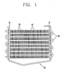
- FIG. 1 illustrates an example of a defroster of a heat exchanger in accordance with the background art.
- the heat exchanger includes a plurality of straight pipes 20 installed between two holders 10.
- each straight pipe 20 is connected by respective curved connection pipes 30.
- Each of the connection pipes 30 is respectively arranged at both sides of the holders 10.
- a plurality of heat transfer fins 40 are also combined with the straight pipes 20.
- the defroster typically includes a heater 50 installed below the heat transfer fins 40.
- the heater 50 having a certain length is curved, and both sides of the heater 50 are respectively combined with the holder 10.
- the heater 50 is installed at an air inlet side of the air flow path in which air flows through the heat exchanger.
- a defroster having the wire type heater has high stability when experiencing vibration or external impact, great caloric power per unit length, and a surface temperature thereof that is typically very high (not less than 500°C).
- the wire type defroster can be typically only be used with a non-environment friendly refrigerant.
- ignition risk is very high because of the great caloric power of this type of heater.
- a refrigerant such as a presently used R-134a
- ignition risk is low.
- an environment-friendly refrigerant such as R600a, etc.
- defrosting is performed by heat generated by the heater 50 arranged at a side of the heat exchanger, defrosting is quickly performed only on portions immediately adjacent to the heater 50. Accordingly a lot of time and power consumption are required for defrosting the entire heat exchanger.
- the present invention overcomes the shortcomings associated with the background art and achieves other advantages not realized by the background art.
- An object of the present invention is to provide a defroster of a heat exchanger and a fabrication method thereof capable of using an environment-friendly, alternative refrigerant and/or for improving a defrosting performance.
- a defroster for a heat exchanger comprising a heat transfer plate having a predetermined area for installing on a heat exchanger; a thin film heater being arranged on the heat transfer plate; and a power supply wire being connected to the film heater for supplying power to the film heater.
- a heat exchanger comprising a plurality of pipes; a plurality of fins; and a defroster, the defroster including a heat transfer plate having a predetermined area and being installed on the heat exchanger; a thin film heater being arranged on the heat transfer plate; and a power supply wire being connected to the film heater for supplying power to the film heater.
- a method for fabricating a defroster of a heat exchanger comprising attaching a masking film having a predetermined shape on a substrate made of an electrically resistant material; patterning a film heater on the substrate based on the predetermined shape of the masking film; adhering the film heater to a heat transfer plate having a predetermined area; and connecting a power supply wire to the film heater.
- FIG. 2 is a perspective view illustrating a defroster of a heat exchanger in accordance with an embodiment of the present invention.
- FIG. 3 is an exploded, perspective view illustrating the defroster of the heat exchanger in accordance with an embodiment of the present invention.
- Common reference numerals have been used to designate common parts in the accompanying drawings.
- the film heater 70 is arranged so as to cover the entire surface area of a side of the heat transfer plate 60.
- the film heater 70 may be constructed as a circuit having a closed-loop shape.
- the film heater 70 may include a square frame line 71 and a plurality of connection lines 72 being connected at regular intervals with the frame line 71 along the length of the heater 70.
- the film heater 70 may be projected or formed onto the surface of the heat transfer plate 60.
- the film heater 70 of a preferred embodiment is made of an electrical resistant material, e.g., aluminum, having a thickness of approximately 20-30 ⁇ m.
- a groove can be formed on the heat transfer plate 60, and the film heater 70 can be inserted into or formed within the groove of the heat transfer plate 60.
- a power supply wire 80 is then connected to a side of the film heater 70 to power the heater 70.
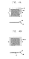
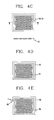
- FIGs. 4A-4E are plan views sequentially illustrating a method for fabricating a defroster of a heat exchanger in accordance with the present invention.
- a substrate 100 having an electrically resistant body is fabricated.
- Masking is then performed on the substrate 100 in a predetermined shape, e.g., in the shape of the film heater 70.
- a masking film 70F having the shape of the film heater 70 is adhered to the substrate 100 during the masking process.
- the substrate 100 can be made of several materials, e.g., preferably aluminum, and formed having a thickness of approximately 20-30 ⁇ m.
- the fabricated defroster is then installed on the heat exchanger.
- the defroster is arranged on a side surface of the heat exchanger so as to be at one side of an air flow path in which air flows through the heat exchanger.
- the heat exchanger is installed on a side of a food storing space in a refrigerator or a showcase, etc.
- the defroster in accordance with the present invention is installed on a side of the heat exchanger.
- a fan installed at a side of the heat exchanger is operated simultaneously with the heat exchanger to produce an air flow for maintaining the food storing space in a cold state while circulating through the heat exchanger. Due to moisture in the food storing space, frost is formed on the surface of the heat exchanger. Power is then supplied to the power supply wire 80 of the defroster when frost is sensed or detected.
- the film heater 70 When power is applied to the power supply wire 80, the film heater 70 is heated and generates heat, the heat is transmitted to the heat exchanger through the heat transfer plate 60, and the frost formed on the heat transfer fin 40 of the heat exchanger is removed.
- the film heater 70 will typically have a surface temperature not greater than 50°C. Heat from the heater 70 is transmitted to the entire heat exchanger through the heat transfer plate 60 for melting any frost.
- defrosting is performed along the whole area of the heat exchanger, a defrosting time is reduced, power consumption is lowered, and efficiency of the defroster is improved.
- the defroster has a low caloric power per unit length that significantly reduces the risk of ignition. Accordingly this defroster can be used safely together with an environment-friendly alternative refrigerant.
Abstract
Description
Claims (20)
- A defroster for a heat exchanger, said defroster comprising:a heat transfer plate having a predetermined area for installing on a heat exchanger;a thin film heater being arranged on the heat transfer plate; anda power supply wire being connected to the film heater for supplying power to the film heater.
- The defroster according to claim 1, wherein the heat transfer plate is made of a flexible material.
- The defroster according to claim 1, wherein the heat transfer plate is made of a metal material.
- The defroster according to claim 1, wherein the heat transfer plate is made of a plastic material.
- The defroster according to claim 1, wherein the thin film heater is arranged so as to cover an entire area of a side of the heat transfer plate.
- The defroster according to claim 1, wherein the thin film heater protrudes from a surface of the heat transfer plate.
- The defroster according to claim 1, wherein the thin film heater is arranged on the heat transfer plate and is inserted into a groove formed on a surface of the heat transfer plate.
- The defroster according to claim 1, wherein the thin film heater is made of aluminum and has a thickness of approximately 20-30 µm.
- A heat exchanger comprising:a plurality of pipes;a plurality of fins; anda defroster, said defroster includinga heat transfer plate having a predetermined area and being installed on the heat exchanger;a thin film heater being arranged on the heat transfer plate; anda power supply wire being connected to the film heater for supplying power to the film heater.
- The heat exchanger according to claim 9, wherein the heat transfer plate is positioned at a first side of an air flow path in which air flows through the heat exchanger.
- The heat exchanger according to claim 9, wherein the heat transfer plate is made of a flexible material.
- The heat exchanger according to claim 9, wherein the heat transfer plate is made of a metal material.
- The heat exchanger according to claim 9, wherein the heat transfer plate is made of a plastic material.
- The heat exchanger according to claim 9, wherein the thin film heater is arranged so as to cover an entire area of a side of the heat transfer plate.
- The heat exchanger according to claim 9, wherein the thin film heater protrudes from a surface of the heat transfer plate.
- The heat exchanger according to claim 9, wherein the thin film heater is arranged on the heat transfer plate and is inserted into a groove formed on a surface of the heat transfer plate.
- The heat exchanger according to claim 9, wherein the thin film heater is made of aluminum and has a thickness of approximately 20-30 µm.
- A method for fabricating a defroster of a heat exchanger, said method comprising:attaching a masking film having a predetermined shape on a substrate made of an electrically resistant material;patterning a film heater on the substrate based on the predetermined shape of the masking film;adhering the film heater to a heat transfer plate having a predetermined area; andconnecting a power supply wire to the film heater.
- The method according to claim 18, wherein the substrate is made of aluminum.
- The method according to claim 18, wherein thickness of the substrate is 20-30 µm.
Applications Claiming Priority (2)
| Application Number | Priority Date | Filing Date | Title |
|---|---|---|---|
| KR1020030022025A KR100664051B1 (en) | 2003-04-08 | 2003-04-08 | Defroster of heat exchanger |
| KR2003022025 | 2003-04-08 |
Publications (2)
| Publication Number | Publication Date |
|---|---|
| EP1467165A1 true EP1467165A1 (en) | 2004-10-13 |
| EP1467165B1 EP1467165B1 (en) | 2009-12-02 |
Family
ID=32866984
Family Applications (1)
| Application Number | Title | Priority Date | Filing Date |
|---|---|---|---|
| EP04000211A Expired - Lifetime EP1467165B1 (en) | 2003-04-08 | 2004-01-08 | Defroster for heat exchanger and fabrication method thereof |
Country Status (9)
| Country | Link |
|---|---|
| US (1) | US7030344B2 (en) |
| EP (1) | EP1467165B1 (en) |
| JP (1) | JP2004309123A (en) |
| KR (1) | KR100664051B1 (en) |
| CN (1) | CN1270150C (en) |
| AT (1) | ATE450765T1 (en) |
| AU (1) | AU2004200021B2 (en) |
| DE (1) | DE602004024349D1 (en) |
| MX (1) | MXPA04000636A (en) |
Cited By (4)
| Publication number | Priority date | Publication date | Assignee | Title |
|---|---|---|---|---|
| EP2290307A2 (en) * | 2008-04-28 | 2011-03-02 | Amogreentech Co., Ltd. | Defrosting heater using strip type plane heating element, manufacturing method thereof and defrosting device using the same |
| WO2012130591A1 (en) * | 2011-03-28 | 2012-10-04 | BSH Bosch und Siemens Hausgeräte GmbH | Refrigerator |
| WO2012130616A3 (en) * | 2011-03-28 | 2012-11-22 | BSH Bosch und Siemens Hausgeräte GmbH | Refrigerator having a heating apparatus |
| RU2507462C1 (en) * | 2012-11-06 | 2014-02-20 | Юлия Алексеевна Щепочкина | Accessory for unfreezing of cast-iron radiators |
Families Citing this family (16)
| Publication number | Priority date | Publication date | Assignee | Title |
|---|---|---|---|---|
| KR100935918B1 (en) * | 2008-04-28 | 2010-01-07 | 주식회사 에이엠오 | Defrost Heater of Surface Type |
| WO2011080089A2 (en) | 2009-12-30 | 2011-07-07 | Arcelik Anonim Sirketi | A cooling device |
| CN102338592B (en) * | 2010-07-27 | 2013-04-24 | 约克广州空调冷冻设备有限公司 | Heat exchanger for heat pump of air conditioner |
| CN102466296B (en) * | 2010-11-10 | 2013-11-20 | 珠海格力电器股份有限公司 | Defrosting control method applied to heat pump air conditioning unit |
| DE102011077838A1 (en) * | 2011-06-20 | 2012-12-20 | Behr Gmbh & Co. Kg | Heat exchanger and method for producing a heat exchanger |
| CN103216978B (en) * | 2013-04-02 | 2015-11-25 | 虞寿仁 | Miniature microchannel heat pump type air conditioner embeds condenser and the defrosting method thereof of heating wire |
| DE102013207375A1 (en) * | 2013-04-23 | 2014-10-23 | Behr Gmbh & Co. Kg | Heat exchanger |
| CN103353203A (en) * | 2013-05-31 | 2013-10-16 | 镇江天信电器有限公司 | Improved mounting structure of defrosting heater |
| CN104567114B (en) * | 2013-10-28 | 2017-08-01 | 珠海格力电器股份有限公司 | Heat exchanger |
| JP6458347B2 (en) * | 2014-03-24 | 2019-01-30 | 大日本印刷株式会社 | Heat exchanger with metal mesh |
| JP2015183933A (en) * | 2014-03-24 | 2015-10-22 | 大日本印刷株式会社 | Freezer with defrosting device |
| CN105157324A (en) * | 2015-09-30 | 2015-12-16 | 合肥华凌股份有限公司 | Defrosting device and refrigerator provided with same |
| US10520240B2 (en) * | 2015-10-21 | 2019-12-31 | Lg Electronics Inc. | Defrosting device and refrigerator having the same |
| CN106705306B (en) * | 2017-01-13 | 2019-09-20 | 西安交通大学 | The integrated operating system of domestic air conditioner and refrigerator |
| CN111102766A (en) * | 2018-10-29 | 2020-05-05 | 博西华电器(江苏)有限公司 | Microchannel heat exchanger and refrigeration appliance |
| CN110285604A (en) * | 2019-06-13 | 2019-09-27 | 合肥美的电冰箱有限公司 | Evaporator assemblies and refrigeration equipment with it |
Citations (4)
| Publication number | Priority date | Publication date | Assignee | Title |
|---|---|---|---|---|
| US5475204A (en) | 1990-06-01 | 1995-12-12 | The B. F. Goodrich Company | Electrical heater de-icer |
| EP1004835A2 (en) | 1998-11-27 | 2000-05-31 | Whirlpool Corporation | Device for rapidly defrosting a refrigerator compartment, such as a freezer compartment or the like |
| EP1120798A2 (en) * | 2000-01-27 | 2001-08-01 | Alper SRL | Heating device, in particular for the defrosting of freezer compartments |
| WO2003008880A1 (en) * | 2001-07-17 | 2003-01-30 | Alper Srl | A device for the rapid defrosting of the surface of evaporators |
Family Cites Families (10)
| Publication number | Priority date | Publication date | Assignee | Title |
|---|---|---|---|---|
| JPH0325058Y2 (en) * | 1986-08-19 | 1991-05-31 | ||
| JPS6370065A (en) * | 1986-09-10 | 1988-03-30 | 株式会社日立ホームテック | Heating element device for defrostation |
| JPS63101636A (en) * | 1986-10-17 | 1988-05-06 | Matsushita Seiko Co Ltd | Auxiliary heater mounting device for air conditioner |
| JPH04353373A (en) | 1991-05-29 | 1992-12-08 | Hitachi Ltd | Heat exchanger and defrosting method thereof |
| US5354966A (en) * | 1991-12-02 | 1994-10-11 | Sperbeck Scott W | Window defogging system with optically clear overlay having multi-layer silver bus bars and electrically isolating peripheral grooves |
| TW250618B (en) * | 1993-01-27 | 1995-07-01 | Mitsui Toatsu Chemicals | |
| JPH06338380A (en) * | 1993-05-28 | 1994-12-06 | Canon Inc | Heater and manufacture thereof |
| JPH1096846A (en) | 1996-09-24 | 1998-04-14 | Jiomatetsuku Kk | Defroster |
| US6504392B2 (en) * | 1999-03-26 | 2003-01-07 | International Business Machines Corporation | Actively controlled heat sink for convective burn-in oven |
| JP2002340468A (en) * | 2001-05-18 | 2002-11-27 | Fujitsu General Ltd | Refrigerator |
-
2003
- 2003-04-08 KR KR1020030022025A patent/KR100664051B1/en not_active IP Right Cessation
- 2003-12-30 US US10/747,200 patent/US7030344B2/en not_active Expired - Fee Related
-
2004
- 2004-01-06 AU AU2004200021A patent/AU2004200021B2/en not_active Ceased
- 2004-01-08 AT AT04000211T patent/ATE450765T1/en not_active IP Right Cessation
- 2004-01-08 DE DE602004024349T patent/DE602004024349D1/en not_active Expired - Lifetime
- 2004-01-08 EP EP04000211A patent/EP1467165B1/en not_active Expired - Lifetime
- 2004-01-21 MX MXPA04000636A patent/MXPA04000636A/en active IP Right Grant
- 2004-02-04 CN CNB2004100040024A patent/CN1270150C/en not_active Expired - Fee Related
- 2004-03-22 JP JP2004082811A patent/JP2004309123A/en active Pending
Patent Citations (4)
| Publication number | Priority date | Publication date | Assignee | Title |
|---|---|---|---|---|
| US5475204A (en) | 1990-06-01 | 1995-12-12 | The B. F. Goodrich Company | Electrical heater de-icer |
| EP1004835A2 (en) | 1998-11-27 | 2000-05-31 | Whirlpool Corporation | Device for rapidly defrosting a refrigerator compartment, such as a freezer compartment or the like |
| EP1120798A2 (en) * | 2000-01-27 | 2001-08-01 | Alper SRL | Heating device, in particular for the defrosting of freezer compartments |
| WO2003008880A1 (en) * | 2001-07-17 | 2003-01-30 | Alper Srl | A device for the rapid defrosting of the surface of evaporators |
Cited By (5)
| Publication number | Priority date | Publication date | Assignee | Title |
|---|---|---|---|---|
| EP2290307A2 (en) * | 2008-04-28 | 2011-03-02 | Amogreentech Co., Ltd. | Defrosting heater using strip type plane heating element, manufacturing method thereof and defrosting device using the same |
| EP2290307A4 (en) * | 2008-04-28 | 2013-05-22 | Amogreentech Co Ltd | Defrosting heater using strip type plane heating element, manufacturing method thereof and defrosting device using the same |
| WO2012130591A1 (en) * | 2011-03-28 | 2012-10-04 | BSH Bosch und Siemens Hausgeräte GmbH | Refrigerator |
| WO2012130616A3 (en) * | 2011-03-28 | 2012-11-22 | BSH Bosch und Siemens Hausgeräte GmbH | Refrigerator having a heating apparatus |
| RU2507462C1 (en) * | 2012-11-06 | 2014-02-20 | Юлия Алексеевна Щепочкина | Accessory for unfreezing of cast-iron radiators |
Also Published As
| Publication number | Publication date |
|---|---|
| US7030344B2 (en) | 2006-04-18 |
| AU2004200021A1 (en) | 2004-10-28 |
| EP1467165B1 (en) | 2009-12-02 |
| CN1270150C (en) | 2006-08-16 |
| AU2004200021B2 (en) | 2006-09-14 |
| US20040200597A1 (en) | 2004-10-14 |
| ATE450765T1 (en) | 2009-12-15 |
| DE602004024349D1 (en) | 2010-01-14 |
| KR100664051B1 (en) | 2007-01-03 |
| CN1536297A (en) | 2004-10-13 |
| MXPA04000636A (en) | 2004-11-12 |
| JP2004309123A (en) | 2004-11-04 |
| KR20040087580A (en) | 2004-10-14 |
Similar Documents
| Publication | Publication Date | Title |
|---|---|---|
| US7030344B2 (en) | Defroster for heat exchanger and fabrication method thereof | |
| CN101995115B (en) | Multi-channel heat exchanger fins | |
| CN102538297B (en) | Outdoor heat exchanger and heat pump having the same | |
| EP3078930B1 (en) | Heat exchanger | |
| US9546804B2 (en) | Microchannel coil spray system | |
| US9574827B2 (en) | Microchannel coil manifold system | |
| JP2007046868A (en) | Evaporator | |
| JP2004069228A (en) | Heat exchanger | |
| WO2020166308A1 (en) | Defrosting device and refrigerator equipped with same | |
| US20220299246A1 (en) | Heat exchanger, indoor unit for air-conditioner, and refrigeration device | |
| US10921045B2 (en) | Roll-bonded evaporator and method of forming the evaporator | |
| JP2004144430A (en) | Heat exchange pipe and heat exchanger | |
| JP2005098581A (en) | Freezing circuit and cooling device using the freezing circuit | |
| JP2004150760A (en) | Heat exchanger | |
| CN107850358B (en) | Heat exchanger and refrigeration cycle device | |
| EP4339540A1 (en) | Heat exchanger | |
| KR100274262B1 (en) | Heat exchanger of air conditioner | |
| KR20240036316A (en) | Heat exchanger | |
| CN110220251A (en) | The manufacturing method of heat exchanger, outdoor unit, freezing cycle device and heat exchanger | |
| US20190360704A1 (en) | Outdoor unit for air-conditioning apparatus | |
| JP2001324283A (en) | Heat exchanger | |
| JP2009275966A (en) | Heat exchanger and refrigerating device comprising the same | |
| KR20040020573A (en) | Evaporator of airconditioner for vehicle | |
| KR19990032939A (en) | Indoor unit of heat pump | |
| JPH07218031A (en) | Engine-driven air-conditioner |
Legal Events
| Date | Code | Title | Description |
|---|---|---|---|
| PUAI | Public reference made under article 153(3) epc to a published international application that has entered the european phase |
Free format text: ORIGINAL CODE: 0009012 |
|
| AK | Designated contracting states |
Kind code of ref document: A1 Designated state(s): AT BE BG CH CY CZ DE DK EE ES FI FR GB GR HU IE IT LI LU MC NL PT RO SE SI SK TR |
|
| AX | Request for extension of the european patent |
Extension state: AL LT LV MK |
|
| 17P | Request for examination filed |
Effective date: 20050317 |
|
| AKX | Designation fees paid |
Designated state(s): AT BE BG CH CY CZ DE DK EE ES FI FR GB GR HU IE IT LI LU MC NL PT RO SE SI SK TR |
|
| 17Q | First examination report despatched |
Effective date: 20081110 |
|
| GRAP | Despatch of communication of intention to grant a patent |
Free format text: ORIGINAL CODE: EPIDOSNIGR1 |
|
| RAP1 | Party data changed (applicant data changed or rights of an application transferred) |
Owner name: LG ELECTRONICS, INC. |
|
| GRAS | Grant fee paid |
Free format text: ORIGINAL CODE: EPIDOSNIGR3 |
|
| GRAA | (expected) grant |
Free format text: ORIGINAL CODE: 0009210 |
|
| AK | Designated contracting states |
Kind code of ref document: B1 Designated state(s): AT BE BG CH CY CZ DE DK EE ES FI FR GB GR HU IE IT LI LU MC NL PT RO SE SI SK TR |
|
| REG | Reference to a national code |
Ref country code: GB Ref legal event code: FG4D |
|
| REG | Reference to a national code |
Ref country code: CH Ref legal event code: EP |
|
| REG | Reference to a national code |
Ref country code: IE Ref legal event code: FG4D |
|
| REF | Corresponds to: |
Ref document number: 602004024349 Country of ref document: DE Date of ref document: 20100114 Kind code of ref document: P |
|
| REG | Reference to a national code |
Ref country code: NL Ref legal event code: VDEP Effective date: 20091202 |
|
| PG25 | Lapsed in a contracting state [announced via postgrant information from national office to epo] |
Ref country code: SE Free format text: LAPSE BECAUSE OF FAILURE TO SUBMIT A TRANSLATION OF THE DESCRIPTION OR TO PAY THE FEE WITHIN THE PRESCRIBED TIME-LIMIT Effective date: 20091202 Ref country code: FI Free format text: LAPSE BECAUSE OF FAILURE TO SUBMIT A TRANSLATION OF THE DESCRIPTION OR TO PAY THE FEE WITHIN THE PRESCRIBED TIME-LIMIT Effective date: 20091202 |
|
| PG25 | Lapsed in a contracting state [announced via postgrant information from national office to epo] |
Ref country code: SI Free format text: LAPSE BECAUSE OF FAILURE TO SUBMIT A TRANSLATION OF THE DESCRIPTION OR TO PAY THE FEE WITHIN THE PRESCRIBED TIME-LIMIT Effective date: 20091202 Ref country code: CY Free format text: LAPSE BECAUSE OF FAILURE TO SUBMIT A TRANSLATION OF THE DESCRIPTION OR TO PAY THE FEE WITHIN THE PRESCRIBED TIME-LIMIT Effective date: 20091202 |
|
| PG25 | Lapsed in a contracting state [announced via postgrant information from national office to epo] |
Ref country code: AT Free format text: LAPSE BECAUSE OF FAILURE TO SUBMIT A TRANSLATION OF THE DESCRIPTION OR TO PAY THE FEE WITHIN THE PRESCRIBED TIME-LIMIT Effective date: 20091202 |
|
| PG25 | Lapsed in a contracting state [announced via postgrant information from national office to epo] |
Ref country code: RO Free format text: LAPSE BECAUSE OF FAILURE TO SUBMIT A TRANSLATION OF THE DESCRIPTION OR TO PAY THE FEE WITHIN THE PRESCRIBED TIME-LIMIT Effective date: 20091202 Ref country code: PT Free format text: LAPSE BECAUSE OF FAILURE TO SUBMIT A TRANSLATION OF THE DESCRIPTION OR TO PAY THE FEE WITHIN THE PRESCRIBED TIME-LIMIT Effective date: 20100402 Ref country code: NL Free format text: LAPSE BECAUSE OF FAILURE TO SUBMIT A TRANSLATION OF THE DESCRIPTION OR TO PAY THE FEE WITHIN THE PRESCRIBED TIME-LIMIT Effective date: 20091202 Ref country code: ES Free format text: LAPSE BECAUSE OF FAILURE TO SUBMIT A TRANSLATION OF THE DESCRIPTION OR TO PAY THE FEE WITHIN THE PRESCRIBED TIME-LIMIT Effective date: 20100313 Ref country code: EE Free format text: LAPSE BECAUSE OF FAILURE TO SUBMIT A TRANSLATION OF THE DESCRIPTION OR TO PAY THE FEE WITHIN THE PRESCRIBED TIME-LIMIT Effective date: 20091202 Ref country code: BG Free format text: LAPSE BECAUSE OF FAILURE TO SUBMIT A TRANSLATION OF THE DESCRIPTION OR TO PAY THE FEE WITHIN THE PRESCRIBED TIME-LIMIT Effective date: 20100302 |
|
| PG25 | Lapsed in a contracting state [announced via postgrant information from national office to epo] |
Ref country code: SK Free format text: LAPSE BECAUSE OF FAILURE TO SUBMIT A TRANSLATION OF THE DESCRIPTION OR TO PAY THE FEE WITHIN THE PRESCRIBED TIME-LIMIT Effective date: 20091202 Ref country code: MC Free format text: LAPSE BECAUSE OF NON-PAYMENT OF DUE FEES Effective date: 20100131 Ref country code: CZ Free format text: LAPSE BECAUSE OF FAILURE TO SUBMIT A TRANSLATION OF THE DESCRIPTION OR TO PAY THE FEE WITHIN THE PRESCRIBED TIME-LIMIT Effective date: 20091202 Ref country code: BE Free format text: LAPSE BECAUSE OF FAILURE TO SUBMIT A TRANSLATION OF THE DESCRIPTION OR TO PAY THE FEE WITHIN THE PRESCRIBED TIME-LIMIT Effective date: 20091202 |
|
| REG | Reference to a national code |
Ref country code: CH Ref legal event code: PL |
|
| PLBI | Opposition filed |
Free format text: ORIGINAL CODE: 0009260 |
|
| PLAX | Notice of opposition and request to file observation + time limit sent |
Free format text: ORIGINAL CODE: EPIDOSNOBS2 |
|
| 26 | Opposition filed |
Opponent name: BSH BOSCH UND SIEMENS HAUSGERAETE GMBH Effective date: 20100831 |
|
| REG | Reference to a national code |
Ref country code: FR Ref legal event code: ST Effective date: 20100930 |
|
| PG25 | Lapsed in a contracting state [announced via postgrant information from national office to epo] |
Ref country code: LI Free format text: LAPSE BECAUSE OF NON-PAYMENT OF DUE FEES Effective date: 20100131 Ref country code: GR Free format text: LAPSE BECAUSE OF FAILURE TO SUBMIT A TRANSLATION OF THE DESCRIPTION OR TO PAY THE FEE WITHIN THE PRESCRIBED TIME-LIMIT Effective date: 20100303 Ref country code: FR Free format text: LAPSE BECAUSE OF NON-PAYMENT OF DUE FEES Effective date: 20100202 Ref country code: CH Free format text: LAPSE BECAUSE OF NON-PAYMENT OF DUE FEES Effective date: 20100131 |
|
| PG25 | Lapsed in a contracting state [announced via postgrant information from national office to epo] |
Ref country code: IE Free format text: LAPSE BECAUSE OF NON-PAYMENT OF DUE FEES Effective date: 20100108 Ref country code: DK Free format text: LAPSE BECAUSE OF FAILURE TO SUBMIT A TRANSLATION OF THE DESCRIPTION OR TO PAY THE FEE WITHIN THE PRESCRIBED TIME-LIMIT Effective date: 20091202 |
|
| PLAF | Information modified related to communication of a notice of opposition and request to file observations + time limit |
Free format text: ORIGINAL CODE: EPIDOSCOBS2 |
|
| PLBB | Reply of patent proprietor to notice(s) of opposition received |
Free format text: ORIGINAL CODE: EPIDOSNOBS3 |
|
| PLCK | Communication despatched that opposition was rejected |
Free format text: ORIGINAL CODE: EPIDOSNREJ1 |
|
| PLBN | Opposition rejected |
Free format text: ORIGINAL CODE: 0009273 |
|
| STAA | Information on the status of an ep patent application or granted ep patent |
Free format text: STATUS: OPPOSITION REJECTED |
|
| 27O | Opposition rejected |
Effective date: 20120321 |
|
| PG25 | Lapsed in a contracting state [announced via postgrant information from national office to epo] |
Ref country code: HU Free format text: LAPSE BECAUSE OF FAILURE TO SUBMIT A TRANSLATION OF THE DESCRIPTION OR TO PAY THE FEE WITHIN THE PRESCRIBED TIME-LIMIT Effective date: 20100603 Ref country code: LU Free format text: LAPSE BECAUSE OF NON-PAYMENT OF DUE FEES Effective date: 20100108 |
|
| REG | Reference to a national code |
Ref country code: DE Ref legal event code: R100 Ref document number: 602004024349 Country of ref document: DE Effective date: 20120321 |
|
| PG25 | Lapsed in a contracting state [announced via postgrant information from national office to epo] |
Ref country code: TR Free format text: LAPSE BECAUSE OF FAILURE TO SUBMIT A TRANSLATION OF THE DESCRIPTION OR TO PAY THE FEE WITHIN THE PRESCRIBED TIME-LIMIT Effective date: 20091202 |
|
| PGFP | Annual fee paid to national office [announced via postgrant information from national office to epo] |
Ref country code: GB Payment date: 20171206 Year of fee payment: 15 |
|
| PGFP | Annual fee paid to national office [announced via postgrant information from national office to epo] |
Ref country code: IT Payment date: 20180115 Year of fee payment: 15 |
|
| GBPC | Gb: european patent ceased through non-payment of renewal fee |
Effective date: 20190108 |
|
| PG25 | Lapsed in a contracting state [announced via postgrant information from national office to epo] |
Ref country code: GB Free format text: LAPSE BECAUSE OF NON-PAYMENT OF DUE FEES Effective date: 20190108 |
|
| PG25 | Lapsed in a contracting state [announced via postgrant information from national office to epo] |
Ref country code: IT Free format text: LAPSE BECAUSE OF NON-PAYMENT OF DUE FEES Effective date: 20190108 |
|
| PGFP | Annual fee paid to national office [announced via postgrant information from national office to epo] |
Ref country code: DE Payment date: 20191205 Year of fee payment: 17 |
|
| REG | Reference to a national code |
Ref country code: DE Ref legal event code: R119 Ref document number: 602004024349 Country of ref document: DE |
|
| PG25 | Lapsed in a contracting state [announced via postgrant information from national office to epo] |
Ref country code: DE Free format text: LAPSE BECAUSE OF NON-PAYMENT OF DUE FEES Effective date: 20210803 |