EP1467156A1 - Fan guard for blower unit - Google Patents
Fan guard for blower unit Download PDFInfo
- Publication number
- EP1467156A1 EP1467156A1 EP03810673A EP03810673A EP1467156A1 EP 1467156 A1 EP1467156 A1 EP 1467156A1 EP 03810673 A EP03810673 A EP 03810673A EP 03810673 A EP03810673 A EP 03810673A EP 1467156 A1 EP1467156 A1 EP 1467156A1
- Authority
- EP
- European Patent Office
- Prior art keywords
- ribs
- extending
- annular
- radial
- fan guard
- Prior art date
- Legal status (The legal status is an assumption and is not a legal conclusion. Google has not performed a legal analysis and makes no representation as to the accuracy of the status listed.)
- Withdrawn
Links
Images





Classifications
-
- F—MECHANICAL ENGINEERING; LIGHTING; HEATING; WEAPONS; BLASTING
- F24—HEATING; RANGES; VENTILATING
- F24F—AIR-CONDITIONING; AIR-HUMIDIFICATION; VENTILATION; USE OF AIR CURRENTS FOR SCREENING
- F24F5/00—Air-conditioning systems or apparatus not covered by F24F1/00 or F24F3/00, e.g. using solar heat or combined with household units such as an oven or water heater
-
- F—MECHANICAL ENGINEERING; LIGHTING; HEATING; WEAPONS; BLASTING
- F04—POSITIVE - DISPLACEMENT MACHINES FOR LIQUIDS; PUMPS FOR LIQUIDS OR ELASTIC FLUIDS
- F04D—NON-POSITIVE-DISPLACEMENT PUMPS
- F04D29/00—Details, component parts, or accessories
- F04D29/70—Suction grids; Strainers; Dust separation; Cleaning
- F04D29/701—Suction grids; Strainers; Dust separation; Cleaning especially adapted for elastic fluid pumps
- F04D29/703—Suction grids; Strainers; Dust separation; Cleaning especially adapted for elastic fluid pumps specially for fans, e.g. fan guards
-
- F—MECHANICAL ENGINEERING; LIGHTING; HEATING; WEAPONS; BLASTING
- F24—HEATING; RANGES; VENTILATING
- F24F—AIR-CONDITIONING; AIR-HUMIDIFICATION; VENTILATION; USE OF AIR CURRENTS FOR SCREENING
- F24F1/00—Room units for air-conditioning, e.g. separate or self-contained units or units receiving primary air from a central station
-
- F—MECHANICAL ENGINEERING; LIGHTING; HEATING; WEAPONS; BLASTING
- F24—HEATING; RANGES; VENTILATING
- F24F—AIR-CONDITIONING; AIR-HUMIDIFICATION; VENTILATION; USE OF AIR CURRENTS FOR SCREENING
- F24F1/00—Room units for air-conditioning, e.g. separate or self-contained units or units receiving primary air from a central station
- F24F1/06—Separate outdoor units, e.g. outdoor unit to be linked to a separate room comprising a compressor and a heat exchanger
- F24F1/38—Fan details of outdoor units, e.g. bell-mouth shaped inlets or fan mountings
-
- F—MECHANICAL ENGINEERING; LIGHTING; HEATING; WEAPONS; BLASTING
- F24—HEATING; RANGES; VENTILATING
- F24F—AIR-CONDITIONING; AIR-HUMIDIFICATION; VENTILATION; USE OF AIR CURRENTS FOR SCREENING
- F24F1/00—Room units for air-conditioning, e.g. separate or self-contained units or units receiving primary air from a central station
- F24F1/06—Separate outdoor units, e.g. outdoor unit to be linked to a separate room comprising a compressor and a heat exchanger
- F24F1/46—Component arrangements in separate outdoor units
- F24F1/48—Component arrangements in separate outdoor units characterised by air airflow, e.g. inlet or outlet airflow
- F24F1/50—Component arrangements in separate outdoor units characterised by air airflow, e.g. inlet or outlet airflow with outlet air in upward direction
Definitions
- the present invention relates to fan guards for air blower unit having blower fans which are mounted at air outlets of the air blower unit.
- air blower units provided in outdoor units of air conditioners, in which, for example, fan guards are provided at air outlets of blower funs for protecting the blower fans.
- fan guards there are well known fan guards in which many radially arranged radial ribs and many coaxially arrange annular ribs are formed integrally by a synthetic resin.
- the radial ribs and the annular ribs of such fun guards made of a synthetic resin have flat sections along the direction of the rotation axis of the blower fans for maintaining the strength and reducing pressure loss of forced airflow flowing between the ribs.
- the fun guards should have enough strength to prevent fingers or foreign matters from entering in error between the annular ribs.
- Pushing an object of a given size with a given force expands the intervals of the annular ribs, so that the object enters.
- strength at the outermost peripheral part where the intervals of the radial ribs become the widest is used as a reference value for design.
- the fan guards with the above structure are fixed at outer frames thereof to the unit bodies. Therefore, the radial ribs works more than the annular ribs for preventing deformation due to load application to the central parts of the fan guards. Hence, the number, the arrangement, the shape of the section and the like of the radial ribs influence much the strength against bending.
- the increase in the ventilating resistance is suppressed while the strength against bending at the central part decreases, with a result that the fan guard is liable to be deformed due to load application to the central part.
- the vanes of the blower fan may come into contact with the thus deformed part of the fan guard.
- the present invention has been made in view of the above problems and has its object of preventing the increase in the ventilating resistance of the forced airflow while ensuring strength to prevent rib expansion and the strength to prevent bending of the fan guard.
- a first invention is directed to a fan guard of a blower unit which is provided with, between a blocking plate 14 arranged at a central part and an outer frame 15 arranged at an outer periphery, a plurality of annular ribs 16, 16 ...arranged coaxially in a radial direction at predetermined intervals with a center of the blocking plate 14 as a center, and a plurality of radial ribs 17, 17 ...extending radially from the blocking plate 14 to the outer frame 15 and arranged at regular intervals in a peripheral direction, and which is mounted at an air outlet 9 of a blower unit A having a blower fan 3 .
- the radial ribs 17 , 17 ... includes a plurality of inner ribs 17B, 17B ...
- the number of the inner ribs 17B, 17B ... is set smaller than the number of the outer ribs 17C, 17C ...
- the inner ribs 17B are connected to the blocking plate 14 , whereby less number of the inner ribs 17B than that of the outer ribs 17C invites no lowering of the strength at the central part of the fun guard 4 . Moreover, sufficient strength to prevent bending of the fan guard 4 at load application in the axial direction can be ensured and the increase in ventilating resistance of the forced airflow W from the blower fan 3 is suppressed.
- the fan guard 4 is prevented from coming into contact with the blower fan 3 due to deformation of the fan guard 4 and noise and required input energy of the blower fan 3 are reduced.
- the radial ribs 17, 17 ... include a plurality of extending ribs 17A, 17A ... extending from the blocking plate 14 to the outer frame 15 and arranged at regular intervals in the peripheral direction in the fan guard of the first invention.
- the inner ribs 17B , 17B ... are arranged between the extending ribs 17A , 17A ..., and the inner ribs 17B , 17B ... and the extending ribs 17A , 17A ... are arranged at regular intervals in the peripheral direction.
- the outer ribs 17C , 17C ... are arranged between the extending ribs 17A , 17A ... and the outer ribs 17C , 17C ..., and the extending ribs 17A , 17A ... are arranged at regular intervals in the peripheral direction.
- the blocking plate 14 and the outer frame 15 are connected with each other by means of the plural extending rib 17A , whereby strength against the load application in the axial direction to the fan guard 4 is increased.
- a thickness t' of the extending ribs 17A , 17A ... is set greater than each thickness t" of the inner ribs 17B, 17B ... and the outer ribs 17C, 17 C ... in the second invention.
- the rigidity of the extending ribs 17A , 17A ... is increased, which increases strength to prevent deformation of the fan guard 4 .
- a length D of the extending ribs 17A, 17A ... in a flow direction of forced airflow W from the blower fan 3 is set longer than each length D' of the inner ribs 17B, 17B ... and the outer ribs 17C, 17C ... in the flow direction of the forced air flow W in the second invention.
- the rigidity of the extending ribs 17A, 17A ... is further increased, which further increases the strength to prevent deformation of the fan guard 4 .
- one of the annular ribs 16 functions as a boundary annular rib 16B serving as a boundary of an inner region Zi and an outer region Zo to which the inner ribs 17B, 17B ... and the outer ribs 17C, 17C ... are connected in the first or second invention.
- a thickness t of the annular ribs 16, 16 ... in the inner region Zi increases gradually from the central part to the boundary annular rib 16B .
- a thickness t of the boundary annular rib 16B is the greatest and a thickness t of outer annular ribs 16C located outside the boundary rib 16B decreases.
- a thickness t of the annular ribs 16, 16 ... in the outer region Zo increases from the thinner annular ribs 16C toward the outer periphery.
- the thickness t of the annular ribs 16 , 16 ... is set greater correspondingly as the intervals of the inner ribs 17B , 17B ... and the outer ribs 17C, 17C ... increase.
- the thickness t of the boundary annular rib 16B which serves as the boundary between the inner region Zi and the outer region Zo to which the inner ribs 17B, 17B ... and the outer ribs 17C, 17C ... are connected, is the greatest, whereby the boundary annular rib 16B exhibits a function as an outer frame for the inner ribs 17B, 17B ... and a function as an inner frame for the outer ribs 17C, 17C ...
- the strength of the fan guard 4 is increased as a whole.
- a chord direction of the radial ribs 17, 17 ... in a rib section on a plane F parallel to a rotary shaft 13a of the blower fan 3 inclines with respect to a rotation axis in the first or second invention.
- an inclined angle ⁇ ' of the radial ribs 17, 17 ... in the chord direction changes in the radial direction so that the incline angle ⁇ ' corresponds to an inclined angle ⁇ of the forced airflow W of the blower fan 3 .
- the radial ribs 17, 17 inclined with respect to the rotation axis on the reference plane F parallel to the rotary shaft 13a of the blower fan 3 and the inclined angle ⁇ ' of the radial ribs 17, 17 ... changes in the radial direction so as to correspond to the inclined angle of the forced airflow W of the blower fan 3 .
- the forced airflow W from the blower fan 3 flows along the radial ribs 17, 17 ... of the fan guard 4 in the entire region in the radial direction of the fan guard 4 .
- interference between the forced airflow and the radial ribs which is caused in the case where there is a region where the inclined angle of the forced airflow does not agree with the inclined angle of the radial ribs (that is, the blocking plate 14 side and the vicinity of the outer periphery), is not caused, resulting in reduction of noise and pressure loss.
- a range of the inclined angle ⁇ ' of the radial ribs 17, 17 ... in the sixth invention includes: a constant region Z0 where the inclined angle ⁇ ' is the smallest at a center between the blocking plate 14 and the outer frame 15 and is substantially constant in a predetermined region; a decreasing region Z1 on the blocking plate 14 side with respect to the constant region Z0 where the inclined angle ⁇ ' decreases as it goes from the blocking plate 14 toward the constant region Z0 ; and an increasing region Z2 on the outer frame 15 side with respect to the constant region Z0 where the inclined angle ⁇ ' increases as it goes toward the outer frame Z0.
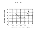
- the change in the inclined angle ⁇ (see FIG. 16 ) of the forced airflow W with respect to the radial direction point agrees with the inclined angle ⁇ ' of the radial ribs 17, 17 ... in the entire region in the radial direction.
- the interference between the forced airflow and the radial ribs which is caused in the case where there is a region where the inclined angle ⁇ of the forced airflow W does not agree with the inclined angle ⁇ ' of the radial ribs 17 , 17 ... (that is, the blocking plate 14 side and the vicinity of the outer periphery), is hardly caused, resulting in reduction of noise and pressure loss.
- the inclined angle ⁇ ' of the radial ribs 17, 17 ... changes within a range from 20 degrees to 50 degrees in the sixth invention.
- the inclined angle ⁇ ' of the radial ribs 17, 17 ... can be appropriately set in the entire region in the radial direction, with a result that noise and pressure loss are surely reduced.
- the annular ribs 16, 16 ... located outside the substantial center in the radial direction inclines outward and an inclined angle ⁇ thereof gradually decreases as it approaches the annular ribs 16, 16 ... in the vicinity of the outermost periphery in the first or second invention.
- the forced airflow W from the blower fan 3 flows along the annular ribs 16, 16 ... Accordingly, interference between the annular ribs 16, 16 ... and the forced airflow W is reduced and the flow direction of the forced airflow W flowing between the annular ribs 16 is corrected in the axial direction in the vicinity of the outermost periphery. As a result, no phenomenon of blocking the forced airflow W is caused, thereby contributing to the reduction of pressure loss.
- the outer frame 15 is in parallel to or inclines inward with respect to the rotary shaft 13a of the blower fan 3 and an inclined angle of an outermost annular rib 16A out of the annular ribs 16, 16 ... is substantially equal to an inclined angle of the outer frame 15 in the first or second invention.
- the forced airflow W smoothly flows between the outermost annular rib 16A and the outer frame 15 .
- noise increase is suppressed and pressure loss is reduced.
- the inner ribs 17B are connected to the blocking plate 14 , whereby less number of the inner ribs 17B than the number of the outer ribs 17C invites no lowering of the strength at the central part of the fan guard 4 , ensures the strength to prevent bending of the fan guard 4 at load application in the axial direction and suppresses the increase in the ventilating resistance of the forced airflow W from the blower fan 3 .
- contact of the fan guard 4 into the blower fan 3 due to deformation of the fan guard 4 can be prevented and reduction of noise and required input energy of the blower fan 3 are implemented.
- the blocking plate 14 and the outer frame 15 are connected by means of the plural radial ribs (extending ribs 17A ), whereby the strength against the load application in the axial direction to the fan guard 4 is increased.
- the rigidity of the extending ribs 17A, 17A ... is increased, which increases the strength against deformation of the fan guard 4 .
- the rigidity of the extending ribs 17A, 17A ... is further increased, which further increases the strength against deformation of the fan guard 4 .
- the thickness t of the annular ribs 16, 16 ... becomes greater as the intervals of the inner ribs 17B, 17B ... and the outer ribs 17C, 17C ... increase, whereby sufficient strength to prevent expansion of the annular ribs 16, 16 ... in the radial direction can be ensured.
- the thickness t of the boundary annular rib 16B which serves as the boundary between the inner region Zi and the outer region Zo to which the inner ribs 17B, 17B ... and the outer ribs 17C, 17C ... are connected, is the greatest, whereby the boundary annular rib 16B exhibits a function as an outer frame for the inner ribs 17B, 17B ...
- the boundary annular rib 16B exhibits a function as an inner frame for the outer ribs 17C, 17C ..., which means increase in the strength of the fan guard 4 as a whole.
- the interference between the forced airflow and the radial ribs which is caused in the case where there is a region where the inclined angle ⁇ of the forced airflow W does not agree with the inclined angle ⁇ ' of the radial ribs 17, 17 ... (that is, the blocking plate 14 side and the vicinity of outer periphery), is not caused, resulting in reduction of noise and pressure loss.
- the change in the inclined angle ⁇ (see FIG. 16) of the forced airflow W with respect to the radial direction point agrees with the inclined angle ⁇ ' of the radial ribs 17, 17 ... in the entire region in the radial direction.
- the interference between the radial ribs and the forced airflow which is caused in the case where there is a region where the inclined angle ⁇ of the forced airflow W does not agree with the inclined angle ⁇ ' of the radial ribs 17, 17 ... (that is, the blocking plate 14 side and the vicinity of the outer periphery), is hardly caused, resulting in reduction of noise and pressure loss.
- the inclined angle ⁇ ' of the radial ribs 17, 17 ... can be appropriately set in the entire region in the radial direction, with a result that noise and pressure loss are surely reduced.
- the forced airflow W from the blower fan 3 flows along the annular ribs 16, 16 ... Accordingly, the interference between the annular ribs 16, 16 ... and the forced airflow W is reduced and the flow direction of the forced airflow W flowing between the annular ribs 16 is corrected in the vicinity of the outermost periphery. As a result, no phenomenon of blocking the forced airflow W is caused, thereby contributing to the reduction of pressure loss.
- the forced airflow W smoothly flows between the outermost annular ribs 16A and the outer frame 15 .
- the noise increase is suppressed and pressure loss is reduced.
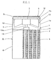
- FIG. 1 through FIG. 8 show a fun guard of a blower unit according to the first embodiment of the present invention.
- the fan guard 4 is, as shown in Fig. 1 , mounted to an outdoor unit A (one example of a blower unit) of an air conditioner.
- the outdoor unit A is of an up-blast type which sucks outside air from the side faces, cools or heats the thus sucked outside air by heat exchange with a refrigerant and blows the thus cooled or heated air upward.
- the outdoor unit A is provided with a casing 1 in a rectangular shape in vertical section having air intake ports 5 on three side faces (only one side face is shown in FIG. 1 ), a heat exchanger 2 in a U-shape in section arranged along each of the air intake ports 5 in the casing 1 , a blower fan 3 for sucking in and blowing out outside air, and a fan guard 4 arranged at the upper end opening part of the casing 1 .
- the outdoor unit A is provided with a control section arranged inside the casing 1 so as to face to the heat exchanger 2, and a compressor for compressing the refrigerant, though not shown in FIG. 1.
- the casing 1 includes a casing body 6 in a rectangular shape of which upper part is opened, and an upper rid member 7 that covers the upper opening of the casing body 6 .
- the casing body 6 is in a box shape made of a thin metal plate formed by, for example a plating process.
- the upper rid member 7 is an integrally formed component made of a synthetic resin and includes a mount portion 7a in a rectangular shape in section mounted on the upper opening of the casing body 6 , and a wall portion 7b in a circular shape extended and narrowed in a tubular shape from the upper end of the mount portion 7a .
- the upper end of the wall portion 7b serves as an air outlet 9 to which the fan guard 4 is fitted.
- a bell mouth 10 substantially in a cylindrical shape of which upper and lower parts are expanded is provided inside the upper part of the mount portion 7a of the upper rid member 7 .
- the blower fan 3 is an axial fan composed of a cylindrical hub 11 located at the center and a plurality of vanes 12, 12 ... arranged around the hub 11 , and is arranged inside the bell mouth 10 .
- the blower fan 3 is driven and rotated by a fan motor 13 having a rotary shaft 13a pivotally mounted at the center of the hub 11 .
- the fan motor 13 is mounted at the upper end of the casing body 6 by means of a support tool (not shown in the drawing).
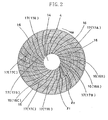
- the fan guard 4 is provided with, between a circular blocking plate 14 arranged at the central part and an annular outer frame 15 arranged at the outer periphery, annular ribs 16 , 16 ...arranged at predetermined intervals in the radial direction coaxially with the center of the blocking plate 14 as a center, and radial ribs 17, 17 ... extending radially from the blocking plate 14 toward the outer frame 15 .
- the radial ribs 17, 17 ... includes: a plurality ( 8 in the present embodiment) of extending ribs 17A, 17A ... extending from the blocking plate 14 to the outer frame 15 ; inner ribs 17B, 17B ... extending from the blocking plate 14 to the substantial center in the radial direction in an inner region Zi ranged from the blocking plate 14 to the substantial center in the radial direction; and outer ribs 17C, 17C ... extending from the substantial center in the radial direction to the outer frame 15 in an outer region Zo ranged from the substantial center in the radial direction to the outer frame 15 .
- the extending ribs 17A, 17A ... are arranged at regular intervals in the peripheral direction and three outer ribs 17C, 17C, 17C and two inner ribs 17B, 17B are arranged at regular intervals in the peripheral direction between adjacent extending ribs 17A , 17A .
- the number of the inner ribs 17B, 17B ... is set to 8 smaller than the number of the outer ribs 17C , 17C ...
- the inner ribs 17B are connected to the blocking plate 14 , whereby less number of the inner ribs 17B than the number of the outer ribs 17C invites no lowering of the strength at the central part of the fan guard 4 . Therefore, the strength to prevent bending of the fan guard 4 at load application in the axial direction to the fan guard 4 is ensured and increase in ventilating resistance of forced airflow W from the blower fan 3 is suppressed.
- the blocking plate 14 and the outer frame 15 are connected by means of the eight extending ribs 17A, 17A ..., whereby the strength against the load application in the axial direction to the fan guard 4 is increased.
- the blocking plate 14 , the outer frame 15 , the extending ribs 17A, 17A ..., the inner ribs 17B, 17B ..., the outer ribs 17C, 17C ... and the annular ribs 16, 16 ... are integrally formed of a synthetic resin (see FIG. 3 ).
- the outer frame 15 is formed in a sleeve shape with a larger diameter than the outer diameter of the vanes 12, 12 ... of the blower fan 3 .
- the fan guard 4 is mounted by fitting the outer frame 15 to the air outlet 9 at the upper end of the wall portion 7b ,.
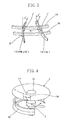
- the extending ribs 17A, 17A ... and the inner ribs 17B, 17B ... are arranged radially in the radial direction from the blocking plate 14 and curves toward the downstream side of the rotational direction M of the blower fan 3 .
- the outer ribs 17C, 17C ... are arranged radially in the radial direction in the outer region Zo of the fan guard 4 and curves toward the downstream side of the rotational direction M of the blower fan 3 .
- the ribs 17A, 17B, 17C become easy to accord with the forced airflow blowing and radially expanding from the blower fan 3 .
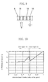
- the ribs 17A, 17B , 17C curve toward the downstream side of the rotational direction M so as to form arcs (see FIG. 4 ).
- an inclined angle ⁇ of the turning forced airflow of the blower fan 3 (that is, an axial fan) is not constant in the entire region in the radial direction and changes in the radial direction.
- the inclined angle ⁇ of the forced airflow changes in the curve that decreases gradually toward the outer periphery from the hub of the axial fan, is the smallest at the point slightly outside the center, becomes constant in a predetermined region and increases gradually in the vicinity of the outer periphery.
- the inclined angle ⁇ gradually changes substantially within the range from 20 degrees to 50 degrees.
- the range of an inclined angle ⁇ ' of the radial ribs includes a constant region Z0 where the angle is the smallest (about 23 degrees, for example) at the center between the blocking plate 14 and the outer frame 15 and is substantially constant in a predetermined region, a decreasing region Z1 on the blocking plate 14 side with respect to the constant region Z0 and an increasing region Z2 on the outer frame 15 side with respect to the constant region Z0 .
- the radial ribs (the extending ribs 17A, the inner ribs 17B and the outer ribs 17C ) are inclined with respect to the rotation axis on a reference plane F parallel to the rotary shaft 13a of the blower fan 3 and the inclined angle ⁇ ' of the radial ribs (the extending ribs 17A, the inner ribs 17B and the outer ribs 17C ) changes in the radial direction gradually so as to correspond to the inclined angle ⁇ of the forced airflow W of the blower fan 3 .
- the incline angle ⁇ ' of the radial ribs (the extending ribs 17A , the inner ribs 17B and the outer ribs 17C ) changes gradually within the range from 20 degrees to 50 degrees.
- chord direction of the radial ribs 17, 17 ... in rib section on the plane F parallel to the rotary shaft 13a of the blower fan 3 inclines with respect to the rotation axis of the blowing fan 3 and the inclined angle ⁇ ' of the ribs 17 , 17 ... in the chord direction changes in the radial direction so as to correspond to the inclined angle ⁇ of the forced airflow W of the blower fan 3 .
- the range of the inclined angle ⁇ ' of the radial ribs 17 , 17 ... includes the constant region Z0 where the inclined angle ⁇ ' is the smallest at the center between the blocking plate 14 and the outer frame 15 and is substantially constant in the predetermined region, the decreasing region Z1 where the incline angle ⁇ ' on the blocking plate 14 side with respect to the constant region Z0 decreases as it goes from the blocking plate 14 toward the constant region Z0, and the increasing region Z2 where the inclined angle ⁇ ' on the outer frame 15 side with respect to the constant region Z0 increases as it approaches the outer frame 15.
- the thickness t' of the extending ribs 17A , 17A ... is set greater than the thickness t" of the inner ribs 17B, 17B ... and the outer ribs 17C, 17C ..., and the length D of the extending ribs 17A, 17A ... in the flow direction of the forced airflow W is set longer than the length D' of the inner ribs 17B, 17B ... and the outer ribs 17C , 17C ...in the flow direction of the forced airflow W (see FIG. 3 ).
- the rigidity of the extending ribs 17A, 17A ... is increased, resulting in increases in the strength against deformation of the fan guard 4 .
- the wall portion 7b of the upper rid member 7 and the outer frame 15 of the fan guard 4 inclines inward with respect to the rotary shaft 13a of the blower fan 3 .
- the outwardly expanding flow from the blower fan 3 (that is, the forced airflow W ) flows along the annular ribs 16, 16 ..., whereby interference between the annular ribs 16 and the forced airflow W is reduced and the flow direction of the forced airflow W flowing between the annular ribs 16 is corrected in the axial direction in the vicinity of the outermost periphery, thereby causing no occlusion of the forced airflow W and reducing pressure loss.
- the inclined angle ⁇ of the outermost annular rib 16A out of the annular ribs 16, 16 ... is set substantially equal to the inclined angle of the outer frame 15 .
- the outer frame 15 may be arranged in parallel to the rotary shaft 13a of the blower fan 3 .
- ⁇ 5 degrees to 15 degrees
- the thickness t of the annular ribs 16, 16 ... increases as the intervals of the inner ribs 17B, 17B ...
- the thickness t of the boundary annular rib 16B which serves as the boundary between the inner region Zi and the outer region Zo to which the inner ribs 17B, 17B ... and the outer ribs 17C, 17C ... are connected, is the greatest, whereby the boundary annular rib 16B exhibits a function as an outer frame for the inner ribs 17B, 17B ... and a function as an inner frame for the outer fibs 17C, 17C ..., with a result that the strength of the fan guard 4 is increased as a whole.
- FIG. 11 shows a fun guard of a blower fan according to the second embodiment of the present invention.
- the radial ribs 17, 17 ... include the inner ribs 17B, 17B ... extending from the blocking plate 14 to the substantial center in the radial direction in the inner region Zi ranged from the blocking plate 14 to the substantial center in the radial direction, and the outer ribs 17C, 17C ... extending from the substantial center in the radial direction to the outer frame 15 in the outer region Zo ranging from the substantial center in the radial direction to the outer frame 1 5.
- the outer ribs 17C, 17C ... and the inner ribs 17B, 17B ... are arranged at regular intervals in the peripheral direction.
- the number of the inner ribs 17B, 17B ... is smaller than the number of the outer ribs 17C, 17C ... (1/2 in the present embodiment).
- the inner ribs 17B are connected to the blocking plate 14 , whereby less number of the inner ribs 17B than the number of the outer ribs 17C invites no lowering of the strength at the central part of the fan guard 4 .
- the strength to prevent bending of the fan guard 4 at load application in the axial direction to the fan guard 4 can be ensured and the increase in the ventilating resistance of the forced airflow W from the blower fan 3 can be suppressed.
- the intervals of the inner ribs 17B, 17B ... and the outer ribs 17C, 17C ... in the peripheral direction are set so that a foreign matter (fingers, for example) hardly enters, and the number of the inner ribs 17B , 17B ... is set smaller than the number of the outer ribs 17C, 17C ... Because the other constitution, operation and effects are the same as those in the first embodiment, the explanation thereof is omitted.
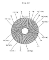
- FIG. 12 shows a fun guard of a blower unit according to the third embodiment of the present invention.
- the number of the extending ribs 17A, 17A ... is set to 12.
- the number of the inner ribs 17B, 17B ... is set to 1/2 of the number of the outer ribs 17C , 17C ...
- the blocking plate 14 may be in the shape of a rectangle.
- FIG. 13 shows a fun guard of a blower unit according to the fourth embodiment of the present invention.
- the number of the extending ribs 17A, 17A ... is set to 6 .
- the number of the inner ribs 17B , 17B ... is set to be 6 smaller than the number of the outer ribs 17C, 17C ...
- the blocking plate 14 may be in the shape of a rectangle.
- FIG. 14 shows a fun guard of a blower unit according to the fifth embodiment of the present invention.
- the outer frame 15 of the fan guard 4 is in the shape of a rectangle.
- the number of the extending ribs 17A, 17A ... is set to 12
- the number of the inner ribs 17B , 17B ... is set to 1/2 of the number of the outer ribs 17C, 17C ...
- the blocking plate 14 may be in the shape of a rectangle.
- FIG. 15 shows a fun guard of a blower unit according to the sixth embodiment of the present invention.
- the outer frame 15 of the fan guard 4 is in the shape of a rectangle.
- the number of the extending ribs 17A, 17A ... is set to 8
- the number of the inner ribs 17B, 17B ... is set to be 8 smaller than the number of the outer ribs 17C, 17C ...
- the blocking plate 14 may be in the shape of a rectangle. Because the other constitution, operation and effects are the same as those in the first embodiment, the explanation thereof is omitted.
- the fan guard of the blower unit according to the present invention is useful when applied to outdoor units of air conditioners, and is especially suitable for outdoor units having annular ribs and radial ribs.
Landscapes
- Engineering & Computer Science (AREA)
- Mechanical Engineering (AREA)
- General Engineering & Computer Science (AREA)
- Chemical & Material Sciences (AREA)
- Combustion & Propulsion (AREA)
- Life Sciences & Earth Sciences (AREA)
- Sustainable Development (AREA)
- Structures Of Non-Positive Displacement Pumps (AREA)
- Other Air-Conditioning Systems (AREA)
Abstract
Description
Claims (10)
- A fan guard of a blower unit which is provided with, between a blocking plate (14) arranged at a central part and an outer frame (15) arranged at an outer periphery, a plurality of annular ribs (16, 16 ...) arranged coaxially in a radial direction at predetermined intervals with a center of the blocking plate (14) as a center, and a plurality of radial ribs (17, 17 ...) extending radially from the blocking plate (14) to the outer frame (15) and arranged at regular intervals in a peripheral direction, and which is mounted at an air outlet (9) of a blower unit (A) having a blower fan (3), characterized in that:the radial ribs (17, 17 ...) includes a plurality of inner ribs (17B, 17B ...) extending from the blocking plate (14) to a substantial center in the radial direction and arranged at regular intervals in the peripheral direction, and a plurality of outer ribs (17C, 17C ...) extending from the substantial center in the radial direction to the outer frame (15) and arranged at regular intervals in the peripheral direction, andthe number of the inner ribs (17B, 17B ...) is set smaller than the number of the outer ribs (17C, 17C ...).
- The fan guard of the blower unit of Claim 1, characterized in that:the radial ribs (17, 17 ...) include a plurality of extending ribs (17A, 17A ...) extending from the blocking plate (14) to the outer frame (15) and arranged at regular intervals in the peripheral direction,the inner ribs (17B, 17B ...) are arranged between the extending ribs (17A, 17A ...), and the inner ribs (17B, 17B ...) and the extending ribs (17A, 17A ...) are arranged at regular intervals in the peripheral direction, andthe outer ribs (17C, 17C ...) are arranged between the extending ribs (17A, 17A ...) and the outer ribs (17C, 17C ...), and the extending ribs (17A, 17A ...) are arranged at regular intervals in the peripheral direction.
- The fan guard of the blower unit of Claim 2, characterized in that:a thickness (t') of the extending ribs (17A, 17A ...) is set greater than each thickness (t") of the inner ribs (17B, 17B ...) and the outer ribs (17C, 17C ...).
- The an guard of the blower unit of Claim 2, characterized in that:a length (D) of the extending ribs (17A, 17A ...) in a flow direction of forced airflow (W) from the blower fan (3) is set longer than each length (D') of the inner ribs (17B, 17B ...) and the outer ribs (17C, 17C ...) in the flow direction of the forced air flow (W).
- The fan guard of the blower unit of Claim 1 or 2, characterized in that:one of the annular ribs (16) functions as a boundary annular rib (16B) serving as a boundary of an inner region (Zi) and an outer region (Zo) to which the inner ribs (17B, 17B ...) and the outer ribs (17C, 17C ...) are connected,a thickness (t) of the annular ribs (16, 16 ...) in the inner region (Zi) increases gradually from the central part to the boundary annular rib (16B), a thickness (t) of the boundary annular rib (16B) is the greatest, a thickness (t) of outer annular ribs (16C) located outside the boundary rib (16B) decreases and a thickness (t) of the annular ribs (16, 16 ...) in the outer region (Zo) increases from the thinner annular ribs (16C) toward the outer periphery.
- The fan guard of the blower unit of Claim 1 or 2, characterized in that:a chord direction of the radial ribs (17, 17 ...) in a rib section on a plane (F) parallel to a rotary shaft (13a) of the blower fan (3) inclines with respect to a rotation axis, and an inclined angle (α') of the radial ribs (17, 17 ...) in the chord direction changes in the radial direction so that the incline angle (α') corresponds to an inclined angle (α) of the forced airflow (W) of the blower fan (3).
- The fan guard of the blower unit of Claim 6, characterized in that:a range of the inclined angle α' of the radial ribs (17, 17 ...) includes: a constant region (Z0) where the inclined angle (α') is the smallest at a center between the blocking plate (14) and the outer frame (15) and is substantially constant in a predetermined region; a decreasing region (Z1) on the blocking plate (14) side with respect to the constant region (Z0) where the inclined angle (α') decreases as it goes from the blocking plate (14) toward the constant region (Z0); and an increasing region (Z2) on the outer frame (15) side with respect to the constant region (Z0) where the inclined angle (α') increases as it goes toward the outer frame (Z0).
- The fan guard of the blower unit of Claim 6, characterized in that:the inclined angel (α') of the radial ribs (17, 17...) changes in a range from 20 degrees to 50 degrees.
- The fan guard of the blower unit of Claim 1 or 2, characterized in that:the annular ribs (16, 16 ...) located outside the substantial center in the radial direction inclines outward and an inclined angle (β) thereof gradually decreases as it approaches the annular ribs (16, 16 ...) in a vicinity of an outermost periphery.
- The fan guard of the blower unit of Claim 1 or 2, characterized in that:the outer frame (15) is in parallel to or inclines inward with respect to a rotary shaft (13a) of the blower fan (3), andan inclined angle of an outermost annular rib (16A) out of the annular ribs (16, 16 ...) is substantially equal to an inclined angle of the outer frame (15).
Applications Claiming Priority (3)
| Application Number | Priority Date | Filing Date | Title |
|---|---|---|---|
| JP2002325284A JP2004156884A (en) | 2002-11-08 | 2002-11-08 | Fan guard for blower unit |
| JP2002325284 | 2002-11-08 | ||
| PCT/JP2003/014229 WO2004042288A1 (en) | 2002-11-08 | 2003-11-07 | Fan guard for blower unit |
Publications (2)
| Publication Number | Publication Date |
|---|---|
| EP1467156A1 true EP1467156A1 (en) | 2004-10-13 |
| EP1467156A4 EP1467156A4 (en) | 2007-11-21 |
Family
ID=32310470
Family Applications (1)
| Application Number | Title | Priority Date | Filing Date |
|---|---|---|---|
| EP03810673A Withdrawn EP1467156A4 (en) | 2002-11-08 | 2003-11-07 | PROTECTIVE GRID FOR BLOWER FAN UNIT |
Country Status (7)
| Country | Link |
|---|---|
| US (1) | US7172387B2 (en) |
| EP (1) | EP1467156A4 (en) |
| JP (1) | JP2004156884A (en) |
| KR (1) | KR100596902B1 (en) |
| CN (1) | CN1333207C (en) |
| AU (1) | AU2003277623B2 (en) |
| WO (1) | WO2004042288A1 (en) |
Cited By (7)
| Publication number | Priority date | Publication date | Assignee | Title |
|---|---|---|---|---|
| EP2314882A1 (en) * | 2009-10-21 | 2011-04-27 | ebm-papst Mulfingen GmbH & Co. KG | Air guiding element for an axial ventilator |
| EP2559905A3 (en) * | 2011-08-18 | 2014-07-30 | Ziehl-Abegg Se | Engine mount for ventilators, preferably axial ventilators, and method for producing a ventilation grill of such an engine mount |
| CN105240325A (en) * | 2015-11-04 | 2016-01-13 | 珠海格力电器股份有限公司 | Electric fan and screen ring thereof |
| WO2016116871A1 (en) * | 2015-01-22 | 2016-07-28 | Elica S.P.A. | Suction grid for an air guide of a domestic hood, air guide having such grid and domestic hood having such air guide. |
| EP3276274A4 (en) * | 2015-03-27 | 2018-12-05 | Mitsubishi Electric Corporation | Indoor unit for air conditioning device |
| EP3399248A3 (en) * | 2012-06-28 | 2019-01-23 | Samsung Electronics Co., Ltd. | Indoor unit of air conditioner and method of controlling the air conditioner |
| EP3527901A4 (en) * | 2016-10-11 | 2019-09-25 | Mitsubishi Electric Corporation | HEAT EXCHANGE VENTILATION DEVICE |
Families Citing this family (29)
| Publication number | Priority date | Publication date | Assignee | Title |
|---|---|---|---|---|
| KR200462303Y1 (en) * | 2007-08-06 | 2012-09-06 | 삼성전자주식회사 | Outdoor unit for air conditioner |
| KR20090043715A (en) * | 2007-10-30 | 2009-05-07 | 삼성전자주식회사 | Fan guard and outdoor unit of air conditioner having same |
| KR101440156B1 (en) * | 2007-12-26 | 2014-09-16 | 엘지전자 주식회사 | The outdoor unit of the air conditioner and its grill |
| JP5199849B2 (en) * | 2008-12-05 | 2013-05-15 | 三菱重工業株式会社 | Vehicle heat exchange module and vehicle equipped with the same |
| WO2012035577A1 (en) * | 2010-09-14 | 2012-03-22 | 三菱電機株式会社 | Blower for outdoor unit, outdoor unit, and refrigeration cycle device |
| CN102032219B (en) * | 2011-01-07 | 2012-10-03 | 佛山市富士宝电器科技股份有限公司 | Fan mesh enclosure |
| WO2012134983A2 (en) * | 2011-03-25 | 2012-10-04 | Vornado Air, Llc | Circular grill for an air circulator unit |
| USD676124S1 (en) | 2011-04-07 | 2013-02-12 | Camair LLC | Pedestal fan parts |
| TWM425950U (en) * | 2011-08-29 | 2012-04-01 | Zhen-Ming Su | Improved fan cover structure of electric fan |
| CN103542468B (en) * | 2012-07-16 | 2016-07-06 | 珠海格力电器股份有限公司 | An air conditioner, an outdoor unit and its fan protection grille |
| US9366266B2 (en) * | 2013-03-14 | 2016-06-14 | Helen Of Troy Limited | Reconfigurable grille and fan assembly including reconfigurable grille |
| US9835176B2 (en) * | 2013-04-05 | 2017-12-05 | Acoustiflo Llc | Fan inlet air handling apparatus and methods |
| CN104930604B (en) * | 2014-03-17 | 2018-02-27 | 珠海格力电器股份有限公司 | Air outlet protection structure, air conditioner outdoor unit and design method of air outlet protection structure |
| TWM497203U (en) * | 2014-10-15 | 2015-03-11 | Zhen-Ming Su | Improved internal-spinning swirl cyclone wind scooper and fan device including the same |
| WO2016121485A1 (en) * | 2015-01-26 | 2016-08-04 | シャープ株式会社 | Fan guard and blower device |
| CN104776581B (en) * | 2015-03-12 | 2017-06-16 | 广东美的制冷设备有限公司 | Air conditioner room unit |
| DE102015115308A1 (en) * | 2015-09-10 | 2017-03-16 | Ebm-Papst Mulfingen Gmbh & Co. Kg | Flow guide for arrangement on a fan |
| KR102489427B1 (en) * | 2016-05-31 | 2023-01-18 | 삼성전자주식회사 | Fan guard assembly and outdoor unit having the same |
| JP6960327B2 (en) * | 2017-12-20 | 2021-11-05 | 三星電子株式会社Samsung Electronics Co., Ltd. | Outdoor unit, air conditioner, fan guard, and fan guard manufacturing method |
| CN108194394A (en) * | 2018-02-07 | 2018-06-22 | 广东美的环境电器制造有限公司 | Preceding screen panel of fan and fan that has it |
| EP3805571A4 (en) * | 2018-06-04 | 2021-05-26 | Mitsubishi Electric Corporation | BLOWER AND REFRIGERATION CYCLE DEVICE |
| KR102600968B1 (en) * | 2018-10-05 | 2023-11-13 | 삼성전자주식회사 | Air conditioner |
| DE102018128792A1 (en) * | 2018-11-16 | 2020-05-20 | Ebm-Papst Mulfingen Gmbh & Co. Kg | Compact diagonal fan with guide device |
| US11686478B2 (en) * | 2020-12-23 | 2023-06-27 | Rheem Manufacturing Company | Grille assembly for air handling unit |
| EP4086463B1 (en) * | 2021-05-06 | 2025-01-22 | Carrier Corporation | An integrated diffuser grille for axial fan |
| US20240125332A1 (en) * | 2022-10-12 | 2024-04-18 | Hanon Systems Efp Deutschland Gmbh | Fan for a heat exchanger of a vehicle |
| CN219101727U (en) * | 2022-12-21 | 2023-05-30 | 台达电子工业股份有限公司 | diversion grille |
| CN116838655B (en) * | 2023-07-25 | 2025-12-12 | 四川长虹空调有限公司 | Fan Protective Cover Design Method |
| CN119802730B (en) * | 2023-10-10 | 2026-06-05 | 青岛海信日立空调系统有限公司 | An air conditioner with a grille |
Family Cites Families (17)
| Publication number | Priority date | Publication date | Assignee | Title |
|---|---|---|---|---|
| US2950859A (en) * | 1956-12-03 | 1960-08-30 | Meier Electric And Machine Com | Fan housing and protective grill |
| JPS54100135A (en) | 1978-01-25 | 1979-08-07 | Toshiba Corp | Air conditioner |
| JPS5716740A (en) * | 1980-07-04 | 1982-01-28 | Hitachi Ltd | Protective unit for blower of air conditioner or the like |
| JPS57179523A (en) | 1981-04-27 | 1982-11-05 | Hitachi Ltd | Fan guard of air conditioner |
| JPS5823298A (en) * | 1981-08-03 | 1983-02-10 | Hitachi Ltd | Safeguard for propeller fan |
| JPS6477798A (en) * | 1987-09-18 | 1989-03-23 | Hitachi Ltd | Protective guard of blower |
| JPH09137970A (en) * | 1995-11-15 | 1997-05-27 | Matsushita Refrig Co Ltd | Outdoor unit of air conditioner |
| JPH09310890A (en) | 1996-05-20 | 1997-12-02 | Mitsubishi Electric Corp | Air conditioner outdoor unit |
| US6015265A (en) * | 1998-08-31 | 2000-01-18 | Lasko Holdings, Inc. | Box fan with air divider ring |
| US6364618B1 (en) * | 2000-02-03 | 2002-04-02 | Lakewood Engineering & Mfg. Co. | Fan body assembly |
| CN2460758Y (en) * | 2000-09-04 | 2001-11-21 | 大金工业株式会社 | Fan Protection cover for blowing device |
| JP4482224B2 (en) * | 2000-12-26 | 2010-06-16 | 東芝キヤリア株式会社 | Air conditioner |
| JP3982181B2 (en) * | 2001-01-29 | 2007-09-26 | ダイキン工業株式会社 | Fan guard for blower unit |
| US6454537B1 (en) * | 2001-04-09 | 2002-09-24 | Lasko Holdings, Inc. | Fan grill construction |
| DE10139542B4 (en) | 2001-08-10 | 2008-07-03 | Moschberger, Udo, Dipl.-Ing. (FH) | Method and device for converting a swirl flow at air outlets with swirl distributors during volume flow measurement with measuring funnels |
| US6695577B1 (en) * | 2002-08-13 | 2004-02-24 | American Power Conversion | Fan grill |
| TWI220919B (en) * | 2003-07-31 | 2004-09-11 | Sunonwealth Electr Mach Ind Co | Airflow guiding structure for a heat dissipating fan |
-
2002
- 2002-11-08 JP JP2002325284A patent/JP2004156884A/en active Pending
-
2003
- 2003-11-07 CN CNB2003801002663A patent/CN1333207C/en not_active Expired - Fee Related
- 2003-11-07 US US10/504,271 patent/US7172387B2/en not_active Expired - Fee Related
- 2003-11-07 AU AU2003277623A patent/AU2003277623B2/en not_active Ceased
- 2003-11-07 KR KR1020047011133A patent/KR100596902B1/en not_active Expired - Fee Related
- 2003-11-07 EP EP03810673A patent/EP1467156A4/en not_active Withdrawn
- 2003-11-07 WO PCT/JP2003/014229 patent/WO2004042288A1/en not_active Ceased
Cited By (8)
| Publication number | Priority date | Publication date | Assignee | Title |
|---|---|---|---|---|
| EP2314882A1 (en) * | 2009-10-21 | 2011-04-27 | ebm-papst Mulfingen GmbH & Co. KG | Air guiding element for an axial ventilator |
| EP2559905A3 (en) * | 2011-08-18 | 2014-07-30 | Ziehl-Abegg Se | Engine mount for ventilators, preferably axial ventilators, and method for producing a ventilation grill of such an engine mount |
| EP3399248A3 (en) * | 2012-06-28 | 2019-01-23 | Samsung Electronics Co., Ltd. | Indoor unit of air conditioner and method of controlling the air conditioner |
| WO2016116871A1 (en) * | 2015-01-22 | 2016-07-28 | Elica S.P.A. | Suction grid for an air guide of a domestic hood, air guide having such grid and domestic hood having such air guide. |
| EP3276274A4 (en) * | 2015-03-27 | 2018-12-05 | Mitsubishi Electric Corporation | Indoor unit for air conditioning device |
| US10627121B2 (en) | 2015-03-27 | 2020-04-21 | Mitsubishi Electric Corporation | Indoor unit for air-conditioning apparatus |
| CN105240325A (en) * | 2015-11-04 | 2016-01-13 | 珠海格力电器股份有限公司 | Electric fan and screen ring thereof |
| EP3527901A4 (en) * | 2016-10-11 | 2019-09-25 | Mitsubishi Electric Corporation | HEAT EXCHANGE VENTILATION DEVICE |
Also Published As
| Publication number | Publication date |
|---|---|
| AU2003277623B2 (en) | 2006-09-07 |
| AU2003277623A1 (en) | 2004-06-07 |
| WO2004042288A1 (en) | 2004-05-21 |
| CN1333207C (en) | 2007-08-22 |
| US20050238481A1 (en) | 2005-10-27 |
| KR20040081751A (en) | 2004-09-22 |
| JP2004156884A (en) | 2004-06-03 |
| US7172387B2 (en) | 2007-02-06 |
| CN1692256A (en) | 2005-11-02 |
| KR100596902B1 (en) | 2006-07-04 |
| EP1467156A4 (en) | 2007-11-21 |
Similar Documents
| Publication | Publication Date | Title |
|---|---|---|
| US7172387B2 (en) | Fan guard for blower unit | |
| US8075262B2 (en) | Centrifugal type blower | |
| EP1357337B1 (en) | Fan guard of fan unit | |
| EP2461042B1 (en) | Air blower for an air conditioner | |
| EP2270338B1 (en) | Blower and heat pump device using same | |
| CN107923410B (en) | Propeller fan, propeller fan device, and outdoor unit for air conditioning device | |
| US11732730B2 (en) | Blower assembly | |
| US7121807B2 (en) | Axial-flow fan | |
| US7163374B2 (en) | Blower fan structure | |
| EP3626974B1 (en) | Outdoor unit for an air conditioner | |
| EP0846868A2 (en) | Centrifugal blower assembly | |
| EP3217018B1 (en) | Propeller fan, propeller fan device, and outdoor equipment for air-conditioning device | |
| JP3812537B2 (en) | Centrifugal blower | |
| JP2004156883A (en) | Fan guard for blower unit | |
| WO2004088210A1 (en) | Outdoor unit for air conditioner | |
| EP3916238A1 (en) | Fan blower, indoor unit, and air conditioner | |
| JP2819873B2 (en) | Cooling device using push-in axial fan | |
| EP1172241B1 (en) | Vehicle air conditioner | |
| JP6970359B2 (en) | Blower and refrigeration system equipped with it | |
| JP2001165093A (en) | Blower | |
| CA3060117A1 (en) | Blower assembly | |
| JP2006526733A (en) | Blower fan |
Legal Events
| Date | Code | Title | Description |
|---|---|---|---|
| PUAI | Public reference made under article 153(3) epc to a published international application that has entered the european phase |
Free format text: ORIGINAL CODE: 0009012 |
|
| 17P | Request for examination filed |
Effective date: 20040804 |
|
| AK | Designated contracting states |
Kind code of ref document: A1 Designated state(s): AT BE BG CH CY CZ DE DK EE ES FI FR GB GR HU IE IT LI LU MC NL PT RO SE SI SK TR |
|
| AX | Request for extension of the european patent |
Extension state: AL LT LV MK |
|
| DAX | Request for extension of the european patent (deleted) | ||
| A4 | Supplementary search report drawn up and despatched |
Effective date: 20071024 |
|
| RIC1 | Information provided on ipc code assigned before grant |
Ipc: F04D 29/70 20060101ALI20071018BHEP Ipc: F24F 5/00 20060101AFI20040525BHEP |
|
| 17Q | First examination report despatched |
Effective date: 20090630 |
|
| STAA | Information on the status of an ep patent application or granted ep patent |
Free format text: STATUS: THE APPLICATION IS DEEMED TO BE WITHDRAWN |
|
| 18D | Application deemed to be withdrawn |
Effective date: 20130608 |