EP1467126A2 - Concept for using software/electronics to calibrate the control system for an automatic transmission - Google Patents
Concept for using software/electronics to calibrate the control system for an automatic transmission Download PDFInfo
- Publication number
- EP1467126A2 EP1467126A2 EP04252132A EP04252132A EP1467126A2 EP 1467126 A2 EP1467126 A2 EP 1467126A2 EP 04252132 A EP04252132 A EP 04252132A EP 04252132 A EP04252132 A EP 04252132A EP 1467126 A2 EP1467126 A2 EP 1467126A2
- Authority
- EP
- European Patent Office
- Prior art keywords
- valve
- coefficients
- characteristic equation
- currents
- electrohydraulic system
- Prior art date
- Legal status (The legal status is an assumption and is not a legal conclusion. Google has not performed a legal analysis and makes no representation as to the accuracy of the status listed.)
- Withdrawn
Links
Images

Classifications
-
- G—PHYSICS
- G05—CONTROLLING; REGULATING
- G05B—CONTROL OR REGULATING SYSTEMS IN GENERAL; FUNCTIONAL ELEMENTS OF SUCH SYSTEMS; MONITORING OR TESTING ARRANGEMENTS FOR SUCH SYSTEMS OR ELEMENTS
- G05B13/00—Adaptive control systems, i.e. systems automatically adjusting themselves to have a performance which is optimum according to some preassigned criterion
- G05B13/02—Adaptive control systems, i.e. systems automatically adjusting themselves to have a performance which is optimum according to some preassigned criterion electric
-
- F—MECHANICAL ENGINEERING; LIGHTING; HEATING; WEAPONS; BLASTING
- F16—ENGINEERING ELEMENTS AND UNITS; GENERAL MEASURES FOR PRODUCING AND MAINTAINING EFFECTIVE FUNCTIONING OF MACHINES OR INSTALLATIONS; THERMAL INSULATION IN GENERAL
- F16H—GEARING
- F16H61/00—Control functions within control units of change-speed- or reversing-gearings for conveying rotary motion ; Control of exclusively fluid gearing, friction gearing, gearings with endless flexible members or other particular types of gearing
- F16H61/02—Control functions within control units of change-speed- or reversing-gearings for conveying rotary motion ; Control of exclusively fluid gearing, friction gearing, gearings with endless flexible members or other particular types of gearing characterised by the signals used
- F16H61/0202—Control functions within control units of change-speed- or reversing-gearings for conveying rotary motion ; Control of exclusively fluid gearing, friction gearing, gearings with endless flexible members or other particular types of gearing characterised by the signals used the signals being electric
- F16H61/0251—Elements specially adapted for electric control units, e.g. valves for converting electrical signals to fluid signals
-
- F—MECHANICAL ENGINEERING; LIGHTING; HEATING; WEAPONS; BLASTING
- F15—FLUID-PRESSURE ACTUATORS; HYDRAULICS OR PNEUMATICS IN GENERAL
- F15B—SYSTEMS ACTING BY MEANS OF FLUIDS IN GENERAL; FLUID-PRESSURE ACTUATORS, e.g. SERVOMOTORS; DETAILS OF FLUID-PRESSURE SYSTEMS, NOT OTHERWISE PROVIDED FOR
- F15B19/00—Testing; Calibrating; Fault detection or monitoring; Simulation or modelling of fluid-pressure systems or apparatus not otherwise provided for
- F15B19/002—Calibrating
-
- F—MECHANICAL ENGINEERING; LIGHTING; HEATING; WEAPONS; BLASTING
- F16—ENGINEERING ELEMENTS AND UNITS; GENERAL MEASURES FOR PRODUCING AND MAINTAINING EFFECTIVE FUNCTIONING OF MACHINES OR INSTALLATIONS; THERMAL INSULATION IN GENERAL
- F16H—GEARING
- F16H59/00—Control inputs to control units of change-speed- or reversing-gearings for conveying rotary motion
- F16H59/68—Inputs being a function of gearing status
- F16H2059/683—Sensing pressure in control systems or in fluid-controlled devices, e.g. by pressure sensors
-
- F—MECHANICAL ENGINEERING; LIGHTING; HEATING; WEAPONS; BLASTING
- F16—ENGINEERING ELEMENTS AND UNITS; GENERAL MEASURES FOR PRODUCING AND MAINTAINING EFFECTIVE FUNCTIONING OF MACHINES OR INSTALLATIONS; THERMAL INSULATION IN GENERAL
- F16H—GEARING
- F16H61/00—Control functions within control units of change-speed- or reversing-gearings for conveying rotary motion ; Control of exclusively fluid gearing, friction gearing, gearings with endless flexible members or other particular types of gearing
- F16H61/02—Control functions within control units of change-speed- or reversing-gearings for conveying rotary motion ; Control of exclusively fluid gearing, friction gearing, gearings with endless flexible members or other particular types of gearing characterised by the signals used
- F16H61/0202—Control functions within control units of change-speed- or reversing-gearings for conveying rotary motion ; Control of exclusively fluid gearing, friction gearing, gearings with endless flexible members or other particular types of gearing characterised by the signals used the signals being electric
- F16H61/0251—Elements specially adapted for electric control units, e.g. valves for converting electrical signals to fluid signals
- F16H2061/0258—Proportional solenoid valve
-
- F—MECHANICAL ENGINEERING; LIGHTING; HEATING; WEAPONS; BLASTING
- F16—ENGINEERING ELEMENTS AND UNITS; GENERAL MEASURES FOR PRODUCING AND MAINTAINING EFFECTIVE FUNCTIONING OF MACHINES OR INSTALLATIONS; THERMAL INSULATION IN GENERAL
- F16H—GEARING
- F16H2342/00—Calibrating
- F16H2342/10—Calibrating valves
Definitions
- This invention relates generally to a software calibration strategy for an electrohydraulic transmission control system and, more particularly, to a software calibration strategy for calibrating solenoids, solenoid controlled valve bodies, or solenoid controlled valve bodies with integrated control units that are used to control an automatic transmission for a vehicle.
- Automatic vehicle transmissions employ a plurality of gears, synchronizers, brake bands and clutches that are electronically controlled to automatically shift the gears of the vehicle.
- solenoid controlled valves are employed within the transmission to provide hydraulic pressure to control the operation of the various components and systems therein, such as clutches, brake bands, lubricant flow, hydraulic pressure, etc.
- the valves are generally proportional valves in that the amount of current applied to the solenoid of the valve determines the hydraulic pressure at the control output of the valve.
- a solenoid controlled valve includes a coil wound around an armature and a valve body.
- the solenoid and the valve body can be attached or separate.
- the valve body is coupled to a hydraulic input line, a hydraulic exhaust line and a hydraulic control output line. Hydraulic supply pressure is applied to the input line.
- the supply pressure applied to the valve is stable, and the control pressure on the output line of the valve is set by the position of the armature.
- the control output line is coupled directly to the exhaust line so that no output pressure is applied to the control line.
- the armature moves so that the hydraulic supply pressure is directed to the control line.
- the amount of current applied to the coil sets the force on the armature, and thus its ability to maintain its regulated output pressure.
- the valve is regulating in that if the load on the control line changes, the armature moves in response thereto to provide the same output pressure for that current.
- Proportional solenoid controlled valves need to be calibrated so that they provide the desired control pressure relative to the input current. If the control valves in the transmission are not properly calibrated, then the performance of the transmission is reduced by a variety of factors, such as lower fuel economy, hard shifts, etc.
- the valve is calibrated by mechanical devices when the valve is manufactured.
- One known mechanical device is a threaded mechanism that increases or decreases a spring force applied to the armature.
- a second mechanical technique for calibrating a solenoid or solenoid piloted valve is to selectively adjust the working air gap between the armature and pole piece of the solenoid, which adjusts the magnetic force level of the device.
- a software calibration strategy is disclosed that has particular application for calibrating solenoid controlled valves and electrohydraulic control systems employed in an automatic transmission.
- the calibration strategy includes identifying a characteristic equation that is unique for a particular class of valves or valve systems, and identifies a mathematical relationship between the current applied to the solenoid and the pressure, or other force such as fluid flow, at the output of the valve or valve system.
- the characteristic equation will include several coefficients that are unique for each separate valve or valve system in the class.
- the valve or valve system is coupled to a test stand that simulates the operation of the valve or valve system in the transmission.
- Control current signals are applied to a solenoid in the valve or valve system and the output pressure (or flow) of the valve or valve system is measured.
- the coefficients for the particular valve or valve system can be determined by using a curve fitting technique, such as a least squares regression, on the characteristic equation. Once the coefficients are identified, they are stored in a flash memory of a transmission control unit (TCU) that is typically integrated into a transmission control module. The coefficients are then used in combination with the characteristic equation, which is part of the vehicle software stored in a TCU memory, to create a unique, high precision, continuous mathematical representation of the valve or valve system performance characteristic.
- TCU transmission control unit
- Figure 1 is a block diagram 70 showing a process for calibrating valve systems and valves in an automatic transmission, according to the invention.
- the calibration strategy of the invention employs a test stand that simulates the operation of the transmission.
- An algorithm is employed to simulate the operation of the transmission to determine the actual pressures or flows at certain operating conditions.
- Each class of valve and/or valve system can be represented by a characteristic equation, the complexity of which is a function of the desired accuracy of the fitting function and the degree of non-linearity and number of inflection points of the actual performance characteristic.
- the characteristic equation for each valve or valve system is part of the transmission control software code, which resides in a TCU memory. This equation does not change from part to part.
- a typical characteristic equation for a proportional control solenoid is provided in equation (1).
- Unique coefficients for the characteristic equation, identified as C 1 , C 2 , C 3 , C 4 and C 5 for the characteristic equation in (1), are created by using a curve fitting technique, for example least-squares regression, using actual measured data obtained during the final test of the valve and/or valve system as an input to the fitting algorithm.
- i ( P ) C 1 + C 2 1+ P + C 3 ⁇ P + C 4 ⁇ P 2 + C 5 P 3 + 0.0001
- the coefficients are flashed to the TCU memory at the end of the final production test procedure, resulting in a unique equation describing the performance characteristic of the valve and/or valve system. It is important to note that because the calibration is performed on the complete system, rather than on the individual components, the overall system variation due to downstream/upstream valve geometry, spring loads, leakage, solenoids, electronics, etc. is significantly reduced.
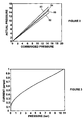
- Figure 2 shows pre and post calibration results obtained from a large population of proportional pressure control devices in a known pressure control system. Upper and lower bounds are shown for the population based on a +/- 5 sigma normal distribution.
- the graph lines 80 and 82 represent a +/- 5 sigma distribution before the calibration, and the graph lines 84 and 86 represent a +/-5 sigma distribution after the calibration.
- the first step of the process at box 72 includes identifying the characteristic equation for a particular valve or valve system, which becomes part of the transmission control software and resides in TCU memory.
- the next step of the process at box 74 includes measuring the output pressure or flow of the valve or valve system for a series of input currents applied to the solenoids discussed above.
- the number of test currents required depends on the number of variables in the characteristic equation and the degree of non-linearity and number of inflection points in the characteristic equation, and the desired accuracy of the fit. In a typical embodiment, the number of test currents may be in the range of 5-8 test currents.
- the next step of the process includes determining the coefficients as represented by box 76.
- the coefficients are determined by a regression technique, for example, a least-squares method, that calculates the coefficients for the characteristic equation that result in a best fit to the measured data obtained in the previous step at the box 74.
- the result is a unique, continuous mathematical relationship between the current applied to the solenoid and the pressure (or flow, position, etc.) at the output of the electrohydraulic system.
- Equation (2) shows a typical characteristic equation, with calculated coefficients, for a proportional pressure control system.
- Figure 3 is a graph with current on the vertical axis and pressure on the horizontal axis showing the general current to pressure relationship for the characteristic equation (1).
Landscapes
- Engineering & Computer Science (AREA)
- General Engineering & Computer Science (AREA)
- Mechanical Engineering (AREA)
- Physics & Mathematics (AREA)
- Fluid Mechanics (AREA)
- Evolutionary Computation (AREA)
- Artificial Intelligence (AREA)
- Computer Vision & Pattern Recognition (AREA)
- Health & Medical Sciences (AREA)
- Medical Informatics (AREA)
- Software Systems (AREA)
- General Physics & Mathematics (AREA)
- Automation & Control Theory (AREA)
- Control Of Transmission Device (AREA)
- Magnetically Actuated Valves (AREA)
- Servomotors (AREA)
- Testing Of Devices, Machine Parts, Or Other Structures Thereof (AREA)
Abstract
Description
- This invention relates generally to a software calibration strategy for an electrohydraulic transmission control system and, more particularly, to a software calibration strategy for calibrating solenoids, solenoid controlled valve bodies, or solenoid controlled valve bodies with integrated control units that are used to control an automatic transmission for a vehicle.
- Automatic vehicle transmissions employ a plurality of gears, synchronizers, brake bands and clutches that are electronically controlled to automatically shift the gears of the vehicle. Typically, solenoid controlled valves are employed within the transmission to provide hydraulic pressure to control the operation of the various components and systems therein, such as clutches, brake bands, lubricant flow, hydraulic pressure, etc. The valves are generally proportional valves in that the amount of current applied to the solenoid of the valve determines the hydraulic pressure at the control output of the valve.
- A solenoid controlled valve includes a coil wound around an armature and a valve body. The solenoid and the valve body can be attached or separate. The valve body is coupled to a hydraulic input line, a hydraulic exhaust line and a hydraulic control output line. Hydraulic supply pressure is applied to the input line. The supply pressure applied to the valve is stable, and the control pressure on the output line of the valve is set by the position of the armature. When no current is applied to the coil, the control output line is coupled directly to the exhaust line so that no output pressure is applied to the control line. When current is applied to the solenoid, the armature moves so that the hydraulic supply pressure is directed to the control line. The amount of current applied to the coil sets the force on the armature, and thus its ability to maintain its regulated output pressure. The valve is regulating in that if the load on the control line changes, the armature moves in response thereto to provide the same output pressure for that current.
- Proportional solenoid controlled valves need to be calibrated so that they provide the desired control pressure relative to the input current. If the control valves in the transmission are not properly calibrated, then the performance of the transmission is reduced by a variety of factors, such as lower fuel economy, hard shifts, etc. Typically, the valve is calibrated by mechanical devices when the valve is manufactured. One known mechanical device is a threaded mechanism that increases or decreases a spring force applied to the armature. A second mechanical technique for calibrating a solenoid or solenoid piloted valve is to selectively adjust the working air gap between the armature and pole piece of the solenoid, which adjusts the magnetic force level of the device.
- The known mechanical techniques of calibrating a solenoid valve are typically costly because the calibration components are expensive to manufacture and the calibration process is time consuming. Further, the equipment required to perform the calibration is expensive and has inherent accuracy limitations. Additionally, the solenoid or solenoid piloted valve is not calibrated to other system components, such as electronics, other valves, leakage, etc, that may affect the valve performance when it is employed in the system.
- In accordance with the teachings of the present invention, a software calibration strategy is disclosed that has particular application for calibrating solenoid controlled valves and electrohydraulic control systems employed in an automatic transmission. The calibration strategy includes identifying a characteristic equation that is unique for a particular class of valves or valve systems, and identifies a mathematical relationship between the current applied to the solenoid and the pressure, or other force such as fluid flow, at the output of the valve or valve system. The characteristic equation will include several coefficients that are unique for each separate valve or valve system in the class.
- The valve or valve system is coupled to a test stand that simulates the operation of the valve or valve system in the transmission. Control current signals are applied to a solenoid in the valve or valve system and the output pressure (or flow) of the valve or valve system is measured. Once the current and corresponding pressure is known for several points, the coefficients for the particular valve or valve system can be determined by using a curve fitting technique, such as a least squares regression, on the characteristic equation. Once the coefficients are identified, they are stored in a flash memory of a transmission control unit (TCU) that is typically integrated into a transmission control module. The coefficients are then used in combination with the characteristic equation, which is part of the vehicle software stored in a TCU memory, to create a unique, high precision, continuous mathematical representation of the valve or valve system performance characteristic.
- Additional advantages and features of the present invention will become apparent from the following description and appended claims, taken in conjunction with the accompanying drawings.
-
- Figure 1 is a flow chart diagram showing a process of calibrating valve and/or valve systems, according to an embodiment of the present invention;
- Figure 2 is a graph with commanded pressure on the horizontal axis and actual pressure on the vertical axis showing the pre/post calibration relationship between the actual measured pressure and the commanded or desired pressure for a large population of proportional pressure control devices; and
- Figure 3 is a graph with current on the vertical axis and pressure on the horizontal axis showing the relationship between current and hydraulic pressure for a clutch pressure control valve in an automatic transmission.
-
- The following discussion of the embodiments of the invention directed to a software calibration strategy for an automatic transmission is merely exemplary in nature, and is in no way intended to limit the invention or its applications or uses.
- Figure 1 is a block diagram 70 showing a process for calibrating valve systems and valves in an automatic transmission, according to the invention. The calibration strategy of the invention employs a test stand that simulates the operation of the transmission. An algorithm is employed to simulate the operation of the transmission to determine the actual pressures or flows at certain operating conditions.
- Each class of valve and/or valve system can be represented by a characteristic equation, the complexity of which is a function of the desired accuracy of the fitting function and the degree of non-linearity and number of inflection points of the actual performance characteristic. The general form of the equation is required input =function (desired output), where the desired output is pressure, flow, etc. and the required input is solenoid current.
- The characteristic equation for each valve or valve system is part of the transmission control software code, which resides in a TCU memory. This equation does not change from part to part. A typical characteristic equation for a proportional control solenoid is provided in equation (1). Unique coefficients for the characteristic equation, identified as C1, C2, C3, C4 and C5 for the characteristic equation in (1), are created by using a curve fitting technique, for example least-squares regression, using actual measured data obtained during the final test of the valve and/or valve system as an input to the fitting algorithm.
C C C C P P - The coefficients are flashed to the TCU memory at the end of the final production test procedure, resulting in a unique equation describing the performance characteristic of the valve and/or valve system. It is important to note that because the calibration is performed on the complete system, rather than on the individual components, the overall system variation due to downstream/upstream valve geometry, spring loads, leakage, solenoids, electronics, etc. is significantly reduced.
- Figure 2 shows pre and post calibration results obtained from a large population of proportional pressure control devices in a known pressure control system. Upper and lower bounds are shown for the population based on a +/- 5 sigma normal distribution. The
graph lines graph lines - The first step of the process at
box 72 includes identifying the characteristic equation for a particular valve or valve system, which becomes part of the transmission control software and resides in TCU memory. The next step of the process atbox 74 includes measuring the output pressure or flow of the valve or valve system for a series of input currents applied to the solenoids discussed above. The number of test currents required depends on the number of variables in the characteristic equation and the degree of non-linearity and number of inflection points in the characteristic equation, and the desired accuracy of the fit. In a typical embodiment, the number of test currents may be in the range of 5-8 test currents. - The next step of the process includes determining the coefficients as represented by
box 76. In one embodiment, the coefficients are determined by a regression technique, for example, a least-squares method, that calculates the coefficients for the characteristic equation that result in a best fit to the measured data obtained in the previous step at thebox 74. The result is a unique, continuous mathematical relationship between the current applied to the solenoid and the pressure (or flow, position, etc.) at the output of the electrohydraulic system. - Equation (2) below shows a typical characteristic equation, with calculated coefficients, for a proportional pressure control system. Once the coefficients are determined by the least-square fitting function or otherwise, the coefficients are stored in a flash memory of the electrohydraulic system, as represented by box 78. The characteristic equation resides in the TCU memory and is imbedded in the transmission control software. Note that the characteristic equation need not be flashed at this time because it is not unique to each part within a given class. Only the coefficients are unique.
P - Figure 3 is a graph with current on the vertical axis and pressure on the horizontal axis showing the general current to pressure relationship for the characteristic equation (1).
- The foregoing discussion discloses and describes merely exemplary embodiments of the present invention. One skilled in the art will readily recognize from such discussion and from the accompanying drawings and claims that various changes, modifications and variations can be made therein without departing from the spirit and scope of the invention as defined in the following claims.
Claims (10)
- A method (70) of calibrating an electrohydraulic control system that provides an output response in response to an input current, said method comprising:identifying a characteristic equation of the electrohydraulic system (72), said characteristic equation including a plurality of coefficients;coupling the electrohydraulic system to a test stand;applying a plurality of currents to the electrohydraulic system;measuring the output response of the electrohydraulic system for each of the plurality of currents (74); andidentifying the coefficients in the characteristic equation from the output response measurements (76).
- The method (70) according to claim 1 wherein identifying the coefficients in the characteristic equation from the output response measurements (72) includes employing a curve fitting function.
- The method (70) according to claim 2 wherein identifying the coefficients in the characteristic equation from the output response measurements (72) includes employing a least squares fitting function.
- The method (70) according to claim 1 further comprising flashing the coefficients in a memory (78).
- The method (70) according to claim 1 further comprising hard-coding the characteristic equation into control software (78).
- The method (70) according to claim 1 wherein the electrohydraulic system includes a proportional solenoid and a hydraulic valve, wherein applying a plurality of currents to the electrohydraulic system includes applying a plurality of currents to the proportional solenoid.
- The method (70) according to claim 1 wherein the electrohydraulic system is employed in an automatic transmission.
- The method (70) according to claim 1 wherein the electrohydraulic system includes an integrated transmission control unit (TCU).
- The method (70) according to claim 1 wherein the output response is selected from the group consisting of pressure and fluid flow.
- The method (70) according to claim 1 wherein applying a plurality of currents to the electrohydraulic system includes applying a plurality of different currents.
Applications Claiming Priority (4)
| Application Number | Priority Date | Filing Date | Title |
|---|---|---|---|
| US46222503P | 2003-04-11 | 2003-04-11 | |
| US462225P | 2003-04-11 | ||
| US789540 | 2004-02-27 | ||
| US10/789,540 US7474948B2 (en) | 2003-04-11 | 2004-02-27 | Concept for using software/electronics to calibrate the control system for an automatic transmission |
Publications (2)
| Publication Number | Publication Date |
|---|---|
| EP1467126A2 true EP1467126A2 (en) | 2004-10-13 |
| EP1467126A3 EP1467126A3 (en) | 2008-08-06 |
Family
ID=32872270
Family Applications (1)
| Application Number | Title | Priority Date | Filing Date |
|---|---|---|---|
| EP04252132A Withdrawn EP1467126A3 (en) | 2003-04-11 | 2004-04-08 | Concept for using software/electronics to calibrate the control system for an automatic transmission |
Country Status (5)
| Country | Link |
|---|---|
| US (1) | US7474948B2 (en) |
| EP (1) | EP1467126A3 (en) |
| JP (1) | JP2004316914A (en) |
| KR (1) | KR20040089497A (en) |
| CN (1) | CN100362248C (en) |
Cited By (2)
| Publication number | Priority date | Publication date | Assignee | Title |
|---|---|---|---|---|
| DE102007000727B4 (en) | 2006-09-15 | 2018-12-27 | Toyota Jidosha Kabushiki Kaisha | Setting method for a vehicle automatic transmission |
| FR3132490A1 (en) | 2022-02-04 | 2023-08-11 | Psa Automobiles Sa | METHOD FOR DEVELOPING A CONTROL LAW EMBEDDED IN A COMPUTER OF AN ELECTRIC OR HYBRID VEHICLE |
Families Citing this family (22)
| Publication number | Priority date | Publication date | Assignee | Title |
|---|---|---|---|---|
| US8321096B2 (en) * | 2003-04-11 | 2012-11-27 | Borg Warner Inc. | Concept for using software/electronics to calibrate the control system for an automatic transmission |
| JP2009008208A (en) * | 2007-06-29 | 2009-01-15 | Toyota Motor Corp | Actuator control system and actuator |
| US8170761B2 (en) * | 2008-03-03 | 2012-05-01 | Delphi Technologies, Inc. | Method for real-time learning of actuator transfer characteristics |
| US9394952B2 (en) | 2008-05-01 | 2016-07-19 | Allison Transmission, Inc. | Method and apparatus for clutch pressure control |
| US8762018B2 (en) * | 2008-05-01 | 2014-06-24 | Allison Transmission, Inc. | Method and apparatus for clutch pressure control |
| EP2435886B1 (en) * | 2009-05-29 | 2013-03-20 | Metso Paper, Inc. | Method for controlling a digital hydraulic controller |
| DE102011005868A1 (en) * | 2011-03-21 | 2012-09-27 | Deere & Company | Valve control device for a vehicle |
| WO2013116031A1 (en) | 2012-01-30 | 2013-08-08 | Borgwarner Inc. | Mono bearing one piece core solenoid |
| EP2861886B1 (en) * | 2012-06-13 | 2023-08-30 | Allison Transmission, Inc. | Method and apparatus for clutch pressure control |
| CN104321576B (en) | 2012-06-21 | 2016-08-24 | 博格华纳公司 | For there being the solenoid motor method of ventilation polluting protection via hydraulic sleeve pipe racks |
| CN104874083A (en) * | 2014-02-28 | 2015-09-02 | 北京谊安医疗系统股份有限公司 | PEEP valve verification method |
| CN105302169B (en) * | 2014-07-29 | 2021-02-12 | 盛美半导体设备(上海)股份有限公司 | Flow control method |
| US9554713B2 (en) * | 2015-03-02 | 2017-01-31 | Global Pediatric Surgical Technology and Education Project, Inc. | Probe stimulator |
| KR20180125570A (en) * | 2016-04-12 | 2018-11-23 | 보르그워너 인코퍼레이티드 | High-pressure hydraulic solenoid valve for automatic transmission |
| WO2017180429A1 (en) * | 2016-04-12 | 2017-10-19 | Borgwarner Inc. | High flow high pressure hydraulic solenoid valve for automatic transmission |
| CN106021702B (en) * | 2016-05-16 | 2020-08-21 | 上海核工程研究设计院 | Method for optimizing action performance of electro-mechanical and hydraulic equipment |
| CN109312875B (en) | 2016-06-28 | 2022-04-05 | 博格华纳公司 | Solenoid with inverted conical armature for solenoid actuated valve |
| CN106321532B (en) * | 2016-11-15 | 2017-12-26 | 安徽江淮汽车集团股份有限公司 | A kind of gearbox tests hydraulic workstation |
| CN110926827A (en) * | 2019-11-30 | 2020-03-27 | 河南科技大学 | Automatic optimization and calibration system for vehicle control parameters |
| US11649609B2 (en) | 2020-11-09 | 2023-05-16 | Caterpillar Inc. | Hydraulic system and methods for an earthmoving machine |
| CN113532721A (en) * | 2021-09-10 | 2021-10-22 | 盛瑞传动股份有限公司 | Testing method of transmission |
| CN117685269A (en) * | 2022-09-02 | 2024-03-12 | 上海汽车集团股份有限公司 | A transmission pressure-current characteristic calibration method, device and equipment |
Citations (1)
| Publication number | Priority date | Publication date | Assignee | Title |
|---|---|---|---|---|
| EP1199499A1 (en) | 2000-10-19 | 2002-04-24 | Nissan Motor Company, Limited | Hydraulic pressure control method and apparatus for an automatic transmission |
Family Cites Families (23)
| Publication number | Priority date | Publication date | Assignee | Title |
|---|---|---|---|---|
| US4815820A (en) | 1986-05-08 | 1989-03-28 | Hughes Aircraft Company | Method and apparatus for aligning a diffraction grating for tuning the output of a laser |
| US4916641A (en) * | 1987-01-16 | 1990-04-10 | Acl Technologies, Inc. | Servovalve analyzer system |
| FR2616931B1 (en) * | 1987-06-22 | 1989-10-06 | Renault | DEVICE FOR MANAGING AN ELECTRO-HYDRAULIC PRESSURE CONTROL |
| US5481187A (en) | 1991-11-29 | 1996-01-02 | Caterpillar Inc. | Method and apparatus for determining the position of an armature in an electromagnetic actuator |
| JP2740705B2 (en) * | 1992-04-08 | 1998-04-15 | 本田技研工業株式会社 | Fluid torque converter characteristic simulation method and apparatus |
| CA2107624C (en) * | 1992-10-05 | 2002-01-08 | Stephen G. Seberger | Electro-pneumatic converter calibration |
| US5518468A (en) | 1994-06-29 | 1996-05-21 | Ford Motor Company | Compensation for fluid viscosity in automatic transmission friction element engagement |
| JP3331844B2 (en) * | 1995-12-19 | 2002-10-07 | アイシン・エィ・ダブリュ株式会社 | Hydraulic control device for automatic transmission |
| US5784945A (en) * | 1997-05-14 | 1998-07-28 | Caterpillar Inc. | Method and apparatus for determining a valve transform |
| US6272401B1 (en) * | 1997-07-23 | 2001-08-07 | Dresser Industries, Inc. | Valve positioner system |
| JPH11201314A (en) * | 1998-01-07 | 1999-07-30 | Unisia Jecs Corp | Solenoid characteristic correction device |
| JP3437085B2 (en) * | 1998-04-09 | 2003-08-18 | 株式会社日立ユニシアオートモティブ | Driving method of solenoid valve |
| US6070485A (en) * | 1998-11-11 | 2000-06-06 | Funk, Sr.; David G. | Pushbutton solenoid shifter |
| US6208280B1 (en) * | 1999-01-11 | 2001-03-27 | Seagate Technology Llc | Converting a pulse-width modulation signal to an analog voltage |
| JP2000280794A (en) * | 1999-03-31 | 2000-10-10 | Fuji Heavy Ind Ltd | Control device for automatic transmission |
| US6214224B1 (en) * | 1999-06-28 | 2001-04-10 | David K. Farley | Filtered showerhead |
| JP3559895B2 (en) * | 1999-10-18 | 2004-09-02 | 日産自動車株式会社 | Hydraulic pressure control device |
| US6341552B1 (en) | 2000-04-27 | 2002-01-29 | Eaton Corporation | Self-calibrating system and method for controlling a hydraulically operated device |
| CA2354837C (en) * | 2000-08-11 | 2005-01-04 | Honda Giken Kogyo Kabushiki Kaisha | Simulator for automatic vehicle transmission controllers |
| US6463949B2 (en) * | 2000-12-08 | 2002-10-15 | Caterpillar Inc. | Method and apparatus for determining a valve status |
| US6865499B2 (en) * | 2001-04-26 | 2005-03-08 | Siemens Energy & Automation, Inc. | Method and apparatus for tuning compensation parameters in a motion control system associated with a mechanical member |
| KR100554602B1 (en) * | 2002-03-29 | 2006-03-03 | 쟈트코 가부시키가이샤 | Calibration control system and method for hydraulic control device in automatic transmission |
| US7231317B2 (en) * | 2003-01-08 | 2007-06-12 | International Business Machines Corporation | Correlating power signatures with automated equipment |
-
2004
- 2004-02-27 US US10/789,540 patent/US7474948B2/en not_active Expired - Fee Related
- 2004-04-08 EP EP04252132A patent/EP1467126A3/en not_active Withdrawn
- 2004-04-08 KR KR1020040024004A patent/KR20040089497A/en not_active Ceased
- 2004-04-09 CN CNB2004100451163A patent/CN100362248C/en not_active Expired - Fee Related
- 2004-04-12 JP JP2004116639A patent/JP2004316914A/en active Pending
Patent Citations (1)
| Publication number | Priority date | Publication date | Assignee | Title |
|---|---|---|---|---|
| EP1199499A1 (en) | 2000-10-19 | 2002-04-24 | Nissan Motor Company, Limited | Hydraulic pressure control method and apparatus for an automatic transmission |
Cited By (2)
| Publication number | Priority date | Publication date | Assignee | Title |
|---|---|---|---|---|
| DE102007000727B4 (en) | 2006-09-15 | 2018-12-27 | Toyota Jidosha Kabushiki Kaisha | Setting method for a vehicle automatic transmission |
| FR3132490A1 (en) | 2022-02-04 | 2023-08-11 | Psa Automobiles Sa | METHOD FOR DEVELOPING A CONTROL LAW EMBEDDED IN A COMPUTER OF AN ELECTRIC OR HYBRID VEHICLE |
Also Published As
| Publication number | Publication date |
|---|---|
| CN1570406A (en) | 2005-01-26 |
| KR20040089497A (en) | 2004-10-21 |
| US7474948B2 (en) | 2009-01-06 |
| CN100362248C (en) | 2008-01-16 |
| JP2004316914A (en) | 2004-11-11 |
| EP1467126A3 (en) | 2008-08-06 |
| US20040230359A1 (en) | 2004-11-18 |
Similar Documents
| Publication | Publication Date | Title |
|---|---|---|
| EP1467126A2 (en) | Concept for using software/electronics to calibrate the control system for an automatic transmission | |
| US8321096B2 (en) | Concept for using software/electronics to calibrate the control system for an automatic transmission | |
| CN100592034C (en) | Mathematical model for determining and calibrating linear sensor output | |
| US8151620B2 (en) | Method for controlling solenoid pressure | |
| US8577571B2 (en) | Clutch pressure control device | |
| US7769493B2 (en) | System and method for controlling flow characteristics | |
| JP2011525225A (en) | Method and apparatus for detecting and compensating pressure transducer errors | |
| US20090183777A1 (en) | System and method for dynamic solenoid response adjust control | |
| US20130327423A1 (en) | Transmission control apparatus and adjustment method for output characteristic thereof | |
| KR100554602B1 (en) | Calibration control system and method for hydraulic control device in automatic transmission | |
| US9829411B2 (en) | Method of calibrating a wet clutch for generating transfer functions on a test bench | |
| US7979184B2 (en) | Automatic transmission solenoid control system and method | |
| US9188221B2 (en) | Adaptive control of a flow control solenoid valve | |
| JPS63212137A (en) | Speed change controller for speed change gear | |
| US9671032B2 (en) | Dynamic current compensation | |
| US6679800B1 (en) | Hydraulic pressure control method and apparatus of an automatic transmission for a vehicle | |
| US7574906B2 (en) | Determining clutch fill volume in an automatic transmission | |
| JP2019074184A (en) | Gear change control device of automatic transmission | |
| US20050192155A1 (en) | Method and system for an adaptation of an engagement of an automated clutch | |
| KR20040041425A (en) | Method of correcting hydraulic deflection for automatic transmission | |
| US20250131170A1 (en) | Method for the automated generation of an individual hydraulic component characteristic map for an individual hydraulic component of a hydraulic component type | |
| EP1199499A1 (en) | Hydraulic pressure control method and apparatus for an automatic transmission | |
| CN115720554A (en) | Method for checking a high selection valve | |
| CN119334628A (en) | Solenoid valve characteristic testing method, electronic device, storage medium, computer program product | |
| KR20140078493A (en) | Hydraulic control method of continuous variable transmission |
Legal Events
| Date | Code | Title | Description |
|---|---|---|---|
| PUAI | Public reference made under article 153(3) epc to a published international application that has entered the european phase |
Free format text: ORIGINAL CODE: 0009012 |
|
| AK | Designated contracting states |
Kind code of ref document: A2 Designated state(s): AT BE BG CH CY CZ DE DK EE ES FI FR GB GR HU IE IT LI LU MC NL PL PT RO SE SI SK TR |
|
| AX | Request for extension of the european patent |
Extension state: AL HR LT LV MK |
|
| RAP1 | Party data changed (applicant data changed or rights of an application transferred) |
Owner name: BORGWARNER INC. |
|
| PUAL | Search report despatched |
Free format text: ORIGINAL CODE: 0009013 |
|
| AK | Designated contracting states |
Kind code of ref document: A3 Designated state(s): AT BE BG CH CY CZ DE DK EE ES FI FR GB GR HU IE IT LI LU MC NL PL PT RO SE SI SK TR |
|
| AX | Request for extension of the european patent |
Extension state: AL HR LT LV MK |
|
| 17P | Request for examination filed |
Effective date: 20081017 |
|
| AKX | Designation fees paid |
Designated state(s): DE FR GB IT |
|
| 17Q | First examination report despatched |
Effective date: 20100225 |
|
| STAA | Information on the status of an ep patent application or granted ep patent |
Free format text: STATUS: THE APPLICATION HAS BEEN WITHDRAWN |
|
| 18W | Application withdrawn |
Effective date: 20101005 |