EP1467109A1 - Threaded fastener - Google Patents
Threaded fastener Download PDFInfo
- Publication number
- EP1467109A1 EP1467109A1 EP04252086A EP04252086A EP1467109A1 EP 1467109 A1 EP1467109 A1 EP 1467109A1 EP 04252086 A EP04252086 A EP 04252086A EP 04252086 A EP04252086 A EP 04252086A EP 1467109 A1 EP1467109 A1 EP 1467109A1
- Authority
- EP
- European Patent Office
- Prior art keywords
- fastener
- tubular section
- shank
- head
- reduced diameter
- Prior art date
- Legal status (The legal status is an assumption and is not a legal conclusion. Google has not performed a legal analysis and makes no representation as to the accuracy of the status listed.)
- Granted
Links
Images
Classifications
-
- F—MECHANICAL ENGINEERING; LIGHTING; HEATING; WEAPONS; BLASTING
- F16—ENGINEERING ELEMENTS AND UNITS; GENERAL MEASURES FOR PRODUCING AND MAINTAINING EFFECTIVE FUNCTIONING OF MACHINES OR INSTALLATIONS; THERMAL INSULATION IN GENERAL
- F16B—DEVICES FOR FASTENING OR SECURING CONSTRUCTIONAL ELEMENTS OR MACHINE PARTS TOGETHER, e.g. NAILS, BOLTS, CIRCLIPS, CLAMPS, CLIPS OR WEDGES; JOINTS OR JOINTING
- F16B35/00—Screw-bolts; Stay-bolts; Screw-threaded studs; Screws; Set screws
- F16B35/04—Screw-bolts; Stay-bolts; Screw-threaded studs; Screws; Set screws with specially-shaped head or shaft in order to fix the bolt on or in an object
- F16B35/06—Specially-shaped heads
-
- F—MECHANICAL ENGINEERING; LIGHTING; HEATING; WEAPONS; BLASTING
- F16—ENGINEERING ELEMENTS AND UNITS; GENERAL MEASURES FOR PRODUCING AND MAINTAINING EFFECTIVE FUNCTIONING OF MACHINES OR INSTALLATIONS; THERMAL INSULATION IN GENERAL
- F16B—DEVICES FOR FASTENING OR SECURING CONSTRUCTIONAL ELEMENTS OR MACHINE PARTS TOGETHER, e.g. NAILS, BOLTS, CIRCLIPS, CLAMPS, CLIPS OR WEDGES; JOINTS OR JOINTING
- F16B31/00—Screwed connections specially modified in view of tensile load; Break-bolts
- F16B31/04—Screwed connections specially modified in view of tensile load; Break-bolts for maintaining a tensile load
-
- F—MECHANICAL ENGINEERING; LIGHTING; HEATING; WEAPONS; BLASTING
- F16—ENGINEERING ELEMENTS AND UNITS; GENERAL MEASURES FOR PRODUCING AND MAINTAINING EFFECTIVE FUNCTIONING OF MACHINES OR INSTALLATIONS; THERMAL INSULATION IN GENERAL
- F16B—DEVICES FOR FASTENING OR SECURING CONSTRUCTIONAL ELEMENTS OR MACHINE PARTS TOGETHER, e.g. NAILS, BOLTS, CIRCLIPS, CLAMPS, CLIPS OR WEDGES; JOINTS OR JOINTING
- F16B35/00—Screw-bolts; Stay-bolts; Screw-threaded studs; Screws; Set screws
- F16B35/04—Screw-bolts; Stay-bolts; Screw-threaded studs; Screws; Set screws with specially-shaped head or shaft in order to fix the bolt on or in an object
Definitions
- the present invention relates generally to the field of fasteners, and more particularly but not exclusively to a threaded fastener having an axially elastic shank.
- Shank 17 includes a curved neck 31.
- neck 31 has an inwardly curved, C-shaped or horseshoe-shaped axial profile.
- neck 31 is elastically deformed thereby to impart stretch to shank 17. More specifically and is shown in the lower half of Figure 2, neck 31 is elastically deformed between threaded member 15 and flange 19 in the same way that a horse shoe may be stretched by applying force to its legs.
- fastener 11 is rotated to advance threaded member 15 into thread bore 23
- shank 17 stretches through the bending in the curved walls of neck 31 to axially preload fastener 11.
Landscapes
- Engineering & Computer Science (AREA)
- General Engineering & Computer Science (AREA)
- Mechanical Engineering (AREA)
- Dowels (AREA)
- Bolts, Nuts, And Washers (AREA)
- Details Of Spanners, Wrenches, And Screw Drivers And Accessories (AREA)
Abstract
Description
- This invention was made with US Government support under Contract No. N00019-91-C-0172 awarded by the Department of the Navy. The Government has certain rights in this invention.
- The present invention relates generally to the field of fasteners, and more particularly but not exclusively to a threaded fastener having an axially elastic shank.
- A common device for clamping together two halves of a mechanical joint is a threaded fastener such as a bolt or a screw. When a threaded fastener is torqued down, the fastener is preloaded to hold the joint tightly together. Over time and through use, the axial dimensions of the clamped members of the joint may change, thereby reducing the preload on the fastener and causing the joint to loosen. Also, a fastener may tend to untorque to cause the joint to loosen. In order to maintain the integrity of the joint, it is usually necessary to re-torque the fasteners periodically.
- According to the present invention in a first aspect there is provided a fastener which comprises: a head portion; a threaded portion; and a resilient shank portion interconnecting the head portion and the threaded portion.
- According to the present invention in a second aspect there is provided a fastener which comprises: a head; a threaded member; and a shank connecting said head and said threaded member, said shank including a first end adjacent said head and a second end adjacent said threaded member, said shank including a tubular section between said first end and said second end, said tubular section having an inner wall and an outer wall, and said tubular section having a curved axial profile.
- According to the present invention in a third aspect there is provided a fastener which comprises: a threaded member; and a shank connected to said threaded member, said shank including a first end and a second end, said shank including a tubular section between said first end and said second end, said tubular section having an inner wall and an outer wall, and said tubular section having a non-uniform axial profile.
- Various preferred and optional features of the invention are set out in the accompanying claims which are to be read as forming part of the present description.
- In accordance with another aspect of the invention there may be provided a fastener including a head, a threaded member, and a resilient shank portion interconnecting the head portion and the threaded portion. The shank portion includes a first end adjacent the head and a second end adjacent the threaded member. The shank includes a tubular section having an inner wall and an outer wall between the first end and the second end. The tubular section has a curved axial profile. The tubular section is axially elastically deformed as the fastener is torqued down.
- Embodiments of the invention will now be described by way of example with reference to the accompanying drawings in which:-
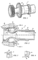
- Figure 1 is a perspective view of a fastener embodying the present invention;
- Figure 2 is a section view of a fastener embodying the present invention engaged with a member;
- Figure 3 is a first detail view taken from Figure 2;
- Figure 4 is a second detail view taken from Figure 2.
-
- Referring now to the drawings, and first to Figure 1, a fastener embodying the present invention is designated generally by the
numeral 11. Fastener 11 is of generally tubular construction having anouter wall 14 and aninner wall 16. Fastener 11 includes ahead 13, a threadedmember 15, and ashank 17 connectinghead 13 and threadedmember 15. -
Head 13 includes a radially outwardly extendingflange 19.Head 13 also includes awrench spline 21 that may be engaged by a spanner wrench or the like to apply torque to fastener 11. Those skilled in the art will recognize thatfastener 11 can include other wrench engaging arrangements, such as wrench flats and the like. - Figure 2 illustrates sectional views of
fastener 11 engaged with a mechanicaljoint including member 23 having a threaded bore and a second member having asmooth bore 25. The upper half of Figure 2 illustratesfastener 11 in hand-tight engagement with thejoint comprising members fastener 11 in torqued engagement with the joint. - As best illustrated in Figure 3,
flange 19 includes a frusto-conical face 27. The taper offace 27 is exaggerated in Figure 3 for purposes of illustration. Preferably, the taper offace 27 is on the order of one degree.Flange 19 may include anannular groove 29 axially rearward offace 27. Whenfastener 11 is torqued to its preloaded position, as illustrated in the lower half of figure 2,flange 19 elastically deforms such thatface 27 becomes flush withmember 25, as illustrated in Figure 4.Groove 29 aids in the elastic deformation offlange 29. - Shank 17 includes a
curved neck 31. As illustrated in Figure 2,neck 31 has an inwardly curved, C-shaped or horseshoe-shaped axial profile. Whenfastener 11 is torqued to its made-up configuration with respect to the joint,neck 31 is elastically deformed thereby to impart stretch toshank 17. More specifically and is shown in the lower half of Figure 2,neck 31 is elastically deformed between threadedmember 15 andflange 19 in the same way that a horse shoe may be stretched by applying force to its legs. Asfastener 11 is rotated to advance threadedmember 15 intothread bore 23,shank 17 stretches through the bending in the curved walls ofneck 31 to axiallypreload fastener 11. The bending deflection results in a total axial deflection infastener 11 that is much greater than that produced by the tensile strain of the material alone or that is produced in a conventional fastener with the same axial load and the same material cross-section. The increased deflection allowsfastener 11 to maintain sufficient preload in the joint while adjusting to changes in the axial dimensions of the clamped members during operation of the joint. As the axial dimension of the joint shortens over time,shank 17 shortens. However, because of the elasticity provided bycurved neck 31,fastener 11 retains sufficient preload to keep the joint tight. The fastener of the present embodiment thus eliminates the requirement of a periodic re-torque as is required with existing fasteners. - The fastener embodying the present invention has been illustrated and described with respect to presently preferred embodiments. Those skilled in the art will recognize other embodiments. For example, while the fastener of the present invention has been illustrated and described as a bolt-type fastener, those skilled in the art will recognize that present invention has applicability to other fasteners such as studs and the like. The foregoing description is for purposes of illustration rather than limitation.
Claims (23)
- A fastener, which comprises:a head portion (13);a threaded portion (15); anda resilient shank portion (17) interconnecting the head portion and the threaded portion.
- A fastener as claimed in Claim 1, wherein said resilient shank portion (17) is defined by a reduced diameter portion (13) between the head portion and the threaded portion (15).
- A fastener as claimed in Claim 1, wherein said head portion (13) includes an outwardly extending flange (19) facing said threaded portion (15).
- A fastener as claimed in Claim 3, wherein said flange (19) includes a frusto-conical face (27).
- A fastener as claimed in Claim 4, wherein said frusto-conical face (27) is tapered inwardly.
- A fastener as claimed in Claim 4, wherein said flange (19) includes a reduced diameter portion axially outward of said frusto-conical face.
- A fastener as claimed in Claim 1, wherein said resilient shank portion (17) is defined by a tubular structure having an outer wall (14) and an inner wall (16).
- A fastener as claimed in Claim 7, said tubular structure includes a reduced diameter portion (31).
- A fastener as claimed in Claim 7, wherein said tubular structure includes a first end adjacent said threaded portion (15) and a second end adjacent said flange portion (19).
- A fastener as claimed in Claim 9, wherein said tubular structure includes a reduced diameter portion (31) intermediate said first and second ends.
- A fastener as claimed in Claim 9, wherein said inner and outer walls (16), (14) are curved between said first and second ends.
- A fastener as claimed in Claim 9, wherein said inner and outer wall (16, 14) have a generally C-shaped axial profile intermediate said first and second ends.
- A fastener as claimed in Claim 12, wherein said generally C-shaped axial profile defines a reduced diameter portion (31) between said first and second ends.
- A fastener, which comprises:a head (13);a threaded member (15); and,a shank (17) connecting said head and said threaded member, said shank including a first end adjacent said head and a second end adjacent said threaded member, said shank including tubular section (31) between said first end and said second end, said tubular section having an inner wall (16) and an outer wall (14), and said tubular section (31) having a curved axial profile.
- A fastener as claimed in Claim 14, wherein said tubular section includes a portion between said first and second end having a generally C-shaped axial profile (31).
- A fastener as claimed in Claim 15, wherein said portion having a C-shaped axial profile defines a reduced diameter portion (31).
- A fastener as claimed in Claim 14, wherein said tubular section includes a reduced diameter portion (31) between said first and second ends.
- A fastener as claimed in Claim 14, wherein said head portion (13) includes an outwardly extending flange (19) facing said threaded portion (15), said flange including an inwardly tapered frusto-conical face (27).
- A fastener as claimed in Claim 18, wherein said flange (19) includes a reduced diameter portion (29) axially outward of said frusto-conical face.
- A fastener, which comprises:a threaded member (15); anda shank (17) connected to said threaded member, said shank including a first end and a second end, said shank including a tubular section (31) between said first end and said second end, said tubular section having an inner wall (16) and an outer wall (14), and said tubular section (31) having a non-uniform axial profile.
- A fastener as claimed in Claim 20, wherein said tubular section includes a portion between said first and second end having a generally C-shaped axial profile (31).
- A fastener as claimed in Claim 21, wherein said portion having a C-shaped axial profile defines a reduced diameter portion (31).
- A fastener as claimed in Claim 20, wherein said tubular section includes a reduced diameter portion (31) between said first and second ends.
Applications Claiming Priority (2)
| Application Number | Priority Date | Filing Date | Title |
|---|---|---|---|
| US10/410,854 US7293948B2 (en) | 2003-04-09 | 2003-04-09 | Flexible threaded fastener |
| US410854 | 2003-04-09 |
Publications (2)
| Publication Number | Publication Date |
|---|---|
| EP1467109A1 true EP1467109A1 (en) | 2004-10-13 |
| EP1467109B1 EP1467109B1 (en) | 2006-06-21 |
Family
ID=32869215
Family Applications (1)
| Application Number | Title | Priority Date | Filing Date |
|---|---|---|---|
| EP04252086A Expired - Lifetime EP1467109B1 (en) | 2003-04-09 | 2004-04-07 | Threaded fastener |
Country Status (6)
| Country | Link |
|---|---|
| US (1) | US7293948B2 (en) |
| EP (1) | EP1467109B1 (en) |
| AU (1) | AU2004201298A1 (en) |
| BR (1) | BRPI0401032A (en) |
| CA (1) | CA2462284C (en) |
| DE (1) | DE602004001260T2 (en) |
Families Citing this family (6)
| Publication number | Priority date | Publication date | Assignee | Title |
|---|---|---|---|---|
| KR101570213B1 (en) | 2007-12-17 | 2015-11-18 | 신세스 게엠바하 | Dynamic bone fixation element and method of using the same |
| DE102009013889A1 (en) * | 2009-03-19 | 2011-01-27 | Liebherr-Hausgeräte Ochsenhausen GmbH | Fridge and / or freezer |
| EP3335655B1 (en) | 2012-03-13 | 2019-07-24 | Synthes GmbH | Dynamic bone fixation element |
| EP3039306B1 (en) * | 2013-08-28 | 2017-07-19 | PEM Management, Inc. | Fastener with a belleville head |
| US9821843B1 (en) * | 2017-01-06 | 2017-11-21 | Robert Bosch Automotive Steering Llc | Tie rod |
| CN114135560A (en) * | 2021-11-30 | 2022-03-04 | Oppo广东移动通信有限公司 | Fastener and electronic device |
Citations (4)
| Publication number | Priority date | Publication date | Assignee | Title |
|---|---|---|---|---|
| DE1023929B (en) * | 1952-12-02 | 1958-02-06 | Amag Hilpert Pegnitzhuette Ag | Stud screw |
| US3067980A (en) * | 1958-11-19 | 1962-12-11 | Gen Motors Corp | Rotating mechanism |
| US3565472A (en) * | 1968-01-19 | 1971-02-23 | Atlas Copco Ab | Screw threaded assemblies |
| GB2085541A (en) * | 1980-10-15 | 1982-04-28 | Goetaverken Motor | A bolt for assembling heat exposed constructions |
Family Cites Families (12)
| Publication number | Priority date | Publication date | Assignee | Title |
|---|---|---|---|---|
| US602378A (en) * | 1898-04-12 | Water-meter | ||
| US969383A (en) * | 1909-08-30 | 1910-09-06 | Myles Mahoney | Stay-bolt. |
| US1172406A (en) * | 1915-09-16 | 1916-02-22 | Thomas B Taylor | Hollow sheet-metal bolt. |
| US1635082A (en) * | 1921-06-15 | 1927-07-05 | Skf Svenska Kullagerfab Ab | Self-locking nut |
| US1926925A (en) * | 1931-04-07 | 1933-09-12 | Gulf Res & Dev Corp | Pin, bolt, and other connecting device |
| NL35533C (en) * | 1932-12-03 | |||
| US2253241A (en) * | 1940-01-16 | 1941-08-19 | Burdsall & Ward Co | Nut or bolt lock |
| US2546332A (en) * | 1946-10-30 | 1951-03-27 | Francis G Costello | Lock nut |
| US2895368A (en) * | 1955-01-21 | 1959-07-21 | Jr Paul R Trigg | Bolt having rolled grooves and recessed head to enhance uniform elongation |
| US3056443A (en) * | 1961-07-17 | 1962-10-02 | Louis T Knocke | Threaded fastener having a resilient locking flange |
| US5102276A (en) * | 1990-07-12 | 1992-04-07 | Ford Motor Company | Removable fastener with elastic linking means |
| US5061137A (en) * | 1991-04-29 | 1991-10-29 | Ford Motor Company | Fastener with resilient linking means |
-
2003
- 2003-04-09 US US10/410,854 patent/US7293948B2/en not_active Expired - Lifetime
-
2004
- 2004-03-25 CA CA2462284A patent/CA2462284C/en not_active Expired - Lifetime
- 2004-03-26 AU AU2004201298A patent/AU2004201298A1/en not_active Abandoned
- 2004-04-07 DE DE602004001260T patent/DE602004001260T2/en not_active Expired - Lifetime
- 2004-04-07 EP EP04252086A patent/EP1467109B1/en not_active Expired - Lifetime
- 2004-04-07 BR BR0401032-9A patent/BRPI0401032A/en not_active IP Right Cessation
Patent Citations (4)
| Publication number | Priority date | Publication date | Assignee | Title |
|---|---|---|---|---|
| DE1023929B (en) * | 1952-12-02 | 1958-02-06 | Amag Hilpert Pegnitzhuette Ag | Stud screw |
| US3067980A (en) * | 1958-11-19 | 1962-12-11 | Gen Motors Corp | Rotating mechanism |
| US3565472A (en) * | 1968-01-19 | 1971-02-23 | Atlas Copco Ab | Screw threaded assemblies |
| GB2085541A (en) * | 1980-10-15 | 1982-04-28 | Goetaverken Motor | A bolt for assembling heat exposed constructions |
Also Published As
| Publication number | Publication date |
|---|---|
| DE602004001260D1 (en) | 2006-08-03 |
| CA2462284A1 (en) | 2004-10-09 |
| US7293948B2 (en) | 2007-11-13 |
| BRPI0401032A (en) | 2005-01-11 |
| AU2004201298A1 (en) | 2004-10-28 |
| DE602004001260T2 (en) | 2007-06-28 |
| EP1467109B1 (en) | 2006-06-21 |
| US20040202526A1 (en) | 2004-10-14 |
| CA2462284C (en) | 2013-01-22 |
Similar Documents
| Publication | Publication Date | Title |
|---|---|---|
| US7306418B2 (en) | Deforming member and captive fastener retaining method | |
| CN100464104C (en) | Ferrule with relief to reduce galling | |
| US8621742B1 (en) | Ferrule lock nuts method | |
| US10316883B2 (en) | Blind nut | |
| JP6885879B2 (en) | Fixtures installed from only one side | |
| US6273655B1 (en) | Anchoring device | |
| US20050053423A1 (en) | Linear fastener system and method for use | |
| HUT62381A (en) | High-strength case fastening binding | |
| IL27268A (en) | Tension stressed fastening unit | |
| CN100494703C (en) | Fastening tool and fastening bolt | |
| US10648500B2 (en) | Blind rivet nut | |
| US10436237B2 (en) | Fastener | |
| US6676345B2 (en) | System for attaching a structural member to a supporting member | |
| US20070224014A1 (en) | Fastener for the temporary joinder of parts made of composite material | |
| US11821448B2 (en) | Blind bolt | |
| US7293948B2 (en) | Flexible threaded fastener | |
| US20240369090A1 (en) | Anchor bolt | |
| JP7449370B2 (en) | expansion anchor | |
| US20080191478A1 (en) | Coupling | |
| JPH10245898A (en) | Ring joint and its fastening jig | |
| JP2021156330A (en) | Blind fastener | |
| AU2008200632B2 (en) | Locking washer | |
| US12140173B2 (en) | Rivet nut with compression limiter shoulder | |
| US20190107142A1 (en) | Nut | |
| CN100529499C (en) | Pipe joint |
Legal Events
| Date | Code | Title | Description |
|---|---|---|---|
| PUAI | Public reference made under article 153(3) epc to a published international application that has entered the european phase |
Free format text: ORIGINAL CODE: 0009012 |
|
| AK | Designated contracting states |
Kind code of ref document: A1 Designated state(s): AT BE BG CH CY CZ DE DK EE ES FI FR GB GR HU IE IT LI LU MC NL PL PT RO SE SI SK TR |
|
| AX | Request for extension of the european patent |
Extension state: AL HR LT LV MK |
|
| 17P | Request for examination filed |
Effective date: 20050105 |
|
| 17Q | First examination report despatched |
Effective date: 20050210 |
|
| AKX | Designation fees paid |
Designated state(s): DE FR GB IT |
|
| GRAP | Despatch of communication of intention to grant a patent |
Free format text: ORIGINAL CODE: EPIDOSNIGR1 |
|
| GRAS | Grant fee paid |
Free format text: ORIGINAL CODE: EPIDOSNIGR3 |
|
| GRAA | (expected) grant |
Free format text: ORIGINAL CODE: 0009210 |
|
| AK | Designated contracting states |
Kind code of ref document: B1 Designated state(s): DE FR GB IT |
|
| PG25 | Lapsed in a contracting state [announced via postgrant information from national office to epo] |
Ref country code: IT Free format text: LAPSE BECAUSE OF FAILURE TO SUBMIT A TRANSLATION OF THE DESCRIPTION OR TO PAY THE FEE WITHIN THE PRESCRIBED TIME-LIMIT;WARNING: LAPSES OF ITALIAN PATENTS WITH EFFECTIVE DATE BEFORE 2007 MAY HAVE OCCURRED AT ANY TIME BEFORE 2007. THE CORRECT EFFECTIVE DATE MAY BE DIFFERENT FROM THE ONE RECORDED. Effective date: 20060621 |
|
| REG | Reference to a national code |
Ref country code: GB Ref legal event code: FG4D |
|
| REF | Corresponds to: |
Ref document number: 602004001260 Country of ref document: DE Date of ref document: 20060803 Kind code of ref document: P |
|
| ET | Fr: translation filed | ||
| PLBE | No opposition filed within time limit |
Free format text: ORIGINAL CODE: 0009261 |
|
| STAA | Information on the status of an ep patent application or granted ep patent |
Free format text: STATUS: NO OPPOSITION FILED WITHIN TIME LIMIT |
|
| 26N | No opposition filed |
Effective date: 20070322 |
|
| PGRI | Patent reinstated in contracting state [announced from national office to epo] |
Ref country code: IT Effective date: 20080601 |
|
| REG | Reference to a national code |
Ref country code: FR Ref legal event code: PLFP Year of fee payment: 13 |
|
| REG | Reference to a national code |
Ref country code: FR Ref legal event code: PLFP Year of fee payment: 14 |
|
| REG | Reference to a national code |
Ref country code: FR Ref legal event code: PLFP Year of fee payment: 15 |
|
| PGFP | Annual fee paid to national office [announced via postgrant information from national office to epo] |
Ref country code: GB Payment date: 20220427 Year of fee payment: 19 Ref country code: FR Payment date: 20220425 Year of fee payment: 19 Ref country code: DE Payment date: 20220427 Year of fee payment: 19 |
|
| PGFP | Annual fee paid to national office [announced via postgrant information from national office to epo] |
Ref country code: IT Payment date: 20230419 Year of fee payment: 20 |
|
| REG | Reference to a national code |
Ref country code: DE Ref legal event code: R119 Ref document number: 602004001260 Country of ref document: DE |
|
| GBPC | Gb: european patent ceased through non-payment of renewal fee |
Effective date: 20230407 |
|
| PG25 | Lapsed in a contracting state [announced via postgrant information from national office to epo] |
Ref country code: GB Free format text: LAPSE BECAUSE OF NON-PAYMENT OF DUE FEES Effective date: 20230407 |
|
| PG25 | Lapsed in a contracting state [announced via postgrant information from national office to epo] |
Ref country code: GB Free format text: LAPSE BECAUSE OF NON-PAYMENT OF DUE FEES Effective date: 20230407 Ref country code: FR Free format text: LAPSE BECAUSE OF NON-PAYMENT OF DUE FEES Effective date: 20230430 Ref country code: DE Free format text: LAPSE BECAUSE OF NON-PAYMENT OF DUE FEES Effective date: 20231103 |