EP1467101A1 - Vane pump - Google Patents
Vane pump Download PDFInfo
- Publication number
- EP1467101A1 EP1467101A1 EP04008629A EP04008629A EP1467101A1 EP 1467101 A1 EP1467101 A1 EP 1467101A1 EP 04008629 A EP04008629 A EP 04008629A EP 04008629 A EP04008629 A EP 04008629A EP 1467101 A1 EP1467101 A1 EP 1467101A1
- Authority
- EP
- European Patent Office
- Prior art keywords
- vane
- rotor
- pump
- outer circumferential
- circumferential edge
- Prior art date
- Legal status (The legal status is an assumption and is not a legal conclusion. Google has not performed a legal analysis and makes no representation as to the accuracy of the status listed.)
- Granted
Links
- 238000004891 communication Methods 0.000 claims abstract description 19
- 230000007423 decrease Effects 0.000 claims description 3
- 239000012530 fluid Substances 0.000 claims description 2
- 238000000638 solvent extraction Methods 0.000 claims description 2
- 230000010349 pulsation Effects 0.000 abstract description 8
- 238000005299 abrasion Methods 0.000 abstract description 7
- 230000003247 decreasing effect Effects 0.000 abstract description 4
- 230000006835 compression Effects 0.000 description 9
- 238000007906 compression Methods 0.000 description 9
- 239000003921 oil Substances 0.000 description 5
- 238000005516 engineering process Methods 0.000 description 3
- 230000000694 effects Effects 0.000 description 2
- 239000010720 hydraulic oil Substances 0.000 description 1
- 238000010348 incorporation Methods 0.000 description 1
- 235000015250 liver sausages Nutrition 0.000 description 1
- 238000012986 modification Methods 0.000 description 1
- 230000004048 modification Effects 0.000 description 1
- 238000005192 partition Methods 0.000 description 1
- 238000007789 sealing Methods 0.000 description 1
- 230000002123 temporal effect Effects 0.000 description 1
Images


Classifications
-
- F—MECHANICAL ENGINEERING; LIGHTING; HEATING; WEAPONS; BLASTING
- F04—POSITIVE - DISPLACEMENT MACHINES FOR LIQUIDS; PUMPS FOR LIQUIDS OR ELASTIC FLUIDS
- F04C—ROTARY-PISTON, OR OSCILLATING-PISTON, POSITIVE-DISPLACEMENT MACHINES FOR LIQUIDS; ROTARY-PISTON, OR OSCILLATING-PISTON, POSITIVE-DISPLACEMENT PUMPS
- F04C18/00—Rotary-piston pumps specially adapted for elastic fluids
- F04C18/30—Rotary-piston pumps specially adapted for elastic fluids having the characteristics covered by two or more of groups F04C18/02, F04C18/08, F04C18/22, F04C18/24, F04C18/48, or having the characteristics covered by one of these groups together with some other type of movement between co-operating members
- F04C18/34—Rotary-piston pumps specially adapted for elastic fluids having the characteristics covered by two or more of groups F04C18/02, F04C18/08, F04C18/22, F04C18/24, F04C18/48, or having the characteristics covered by one of these groups together with some other type of movement between co-operating members having the movement defined in group F04C18/08 or F04C18/22 and relative reciprocation between the co-operating members
- F04C18/344—Rotary-piston pumps specially adapted for elastic fluids having the characteristics covered by two or more of groups F04C18/02, F04C18/08, F04C18/22, F04C18/24, F04C18/48, or having the characteristics covered by one of these groups together with some other type of movement between co-operating members having the movement defined in group F04C18/08 or F04C18/22 and relative reciprocation between the co-operating members with vanes reciprocating with respect to the inner member
- F04C18/3446—Rotary-piston pumps specially adapted for elastic fluids having the characteristics covered by two or more of groups F04C18/02, F04C18/08, F04C18/22, F04C18/24, F04C18/48, or having the characteristics covered by one of these groups together with some other type of movement between co-operating members having the movement defined in group F04C18/08 or F04C18/22 and relative reciprocation between the co-operating members with vanes reciprocating with respect to the inner member the inner and outer member being in contact along more than one line or surface
-
- F—MECHANICAL ENGINEERING; LIGHTING; HEATING; WEAPONS; BLASTING
- F01—MACHINES OR ENGINES IN GENERAL; ENGINE PLANTS IN GENERAL; STEAM ENGINES
- F01C—ROTARY-PISTON OR OSCILLATING-PISTON MACHINES OR ENGINES
- F01C21/00—Component parts, details or accessories not provided for in groups F01C1/00 - F01C20/00
- F01C21/08—Rotary pistons
- F01C21/0809—Construction of vanes or vane holders
- F01C21/0818—Vane tracking; control therefor
- F01C21/0854—Vane tracking; control therefor by fluid means
- F01C21/0863—Vane tracking; control therefor by fluid means the fluid being the working fluid
Definitions
- the present invention relates to a vane pump suitable for use as hydraulic pressure supply to a power steering device and in particularly, to an improvement in a vane guide arrangement for smoothening radial movements of vanes around at each of ejection ports.
- Plural arc backpressure grooves communicating with innermost end portions of the slits and plural arc communication grooves connecting the backpressure grooves one after another are engraved at an inside end surface of each side wall member on which the rotor rotationally slides, and are supplied with the pump ejection pressure. Further, a recess (or cutout) portion which does not contact the side surface of each vane is formed on at least one of rotor sliding surfaces of the side wall members.
- FIG 4 shows one side plate 1 incorporated in the aforementioned prior art vane pump.
- the side plate 1 corresponds to a side plate 20 used a vane pump in the embodiment whose longitudinal sectional view is shown in Figure 1, as referred to later in detail.
- the side plate 1 in the prior art vane pump has a rotor sliding inside end surface, on which there are engraved a pair of right and left suction ports 21 and a pair of upper and lower ejection ports 22.
- an annular backpressure groove 2 is engraved to encircle a through bore 1 a which a pump shaft for driving a rotor passes through.
- the backpressure groove 2 is constituted by a pair of right and left suction backpressure grooves 3 each being radially wide and taking an arc shape, a pair of upper and lower ejection backpressure grooves 4 each being radially wide and taking an arc shape, plural arc communication grooves 5 each being narrow in radial width, and a pair of cutout or recess portions 6.
- Each of the suction backpressure grooves 3 is arranged radially inside of a corresponding one of the suction ports 21 at an angular or circumferential position close to the same, while each of the ejection backpressure grooves 4 is arranged radially inside of a corresponding one of the ejection ports 22 at a circumferential position close to the same.
- Each of the communication grooves 5 makes adjoining suction and ejection backpressure grooves 3, 4 communicate with each other.
- Each of the recess portions 6 is provided to prevent the radially inner part of the side surface of each vane from contacting the inside end surface of the side plate 1 over an angular area where each vane rotating counterclockwise in Figure 4 remains protruded to the radial outermost position and over another angular area where it is moved radially inwardly (i.e., the pre-compression area and compression area shown in Figure 4 of the aforementioned United States patent).
- a passage (not shown) is provided to make each suction backpressure groove 3 communicate with the ejection ports 22.
- Each recess portion 6 in the prior art technology is formed to cover an angular area which ranges from an angular position slightly leaving the rotationally preceding end of each suction backpressure groove 3 to the rotationally preceding end of each ejection backpressure groove 4.
- the axial depth of each recess portion 6 is the same degree as those of the communication grooves 5 and is shallower than those of the suction and ejection backpressure grooves 3, 4.
- the outer circumferential edge of each recess portion 6 is an arc shape which is somewhat larger in radius than the locus (L) drawn by the radially innermost end of each vane and takes its center on the center of the through bore 1 a.
- the contact length of the side surface of each vane with the inside end surface of the side plate 1 is shortened by providing the recess portion 6.
- sliding resistance is decreased between the inside end surface of the side plate 1 and the side surface of each vane as well as between each vane and the rotor slit receiving the same.
- an increased pressure in each ejection backpressure groove 4 which is attributed to the radially inward movement of each van is applied by way of the recess portion 6 to the radial innermost end of the vane in an angular area where the same is to be protruded to the outermost position, so that the vane can be enabled to protrude quickly from the rotor at the start of the pump operation.
- each vane supported in the rotor In vane pumps of this type, the radial movement of each vane supported in the rotor is done with the side surface thereof being slidably guided on the inside end surface of the side plate 1 in the same manner as shown in Figure 1 and 2 of the accompanying drawings.
- the inside end surface of the side plate 1 for slidably guiding and supporting the side surface of each vane which is radially inwardly moved by being pressed along the cam surface of the cam ring upon rotation of the rotor defines a guide area, whose radial width is almost constant and narrow, between the outer circumferential edge of each arc shape recess portion 6 and the inner circumferential edge of each arc shape ejection port 22, as indicated at "e" in Figure 4.
- the inside end surface of the side plate (side wall member) 1 which slidably guides the side surface of each vane in the angular area over which each ejection port elongates is the guide area (e) whose radial width is almost constant and narrow. This tends to cause each vane passing there to incline relative to the side plate 1, and thus, the side plate 1 is insufficient to guide each vane.
- the force which causes each vane rotating with the rotor to move radially inwardly within the same angular area is generated by sliding the radial outer end of each vane on the slanted cam surface at the internal surface of the cam ring against the friction force therebetween.
- each vane tends to involve self-induced vibration and varies irregularly in terms of time and place.
- each vane is inclined relative to the guide area (e) to scrape against the same and cannot move stably and smoothly. For this reason, there arises a problem that the cam surface at the internal surface of the cam ring is abraded notably within the aforementioned angular area, thereby generating pulsation in the pump ejection pressure as well as increasing the operation noise.
- the backpressure groove 2 is formed by extending the suction backpressure grooves 3 (or the ejection backpressure grooves 4) continuously over the whole circumferential length.
- a vane pump section is composed of a cam ring contained in a pump housing, a rotor rotatably provided in the cam ring with a plurality of slits formed in radial direction, and a plurality of vanes guided to be radially slidable respectively in the slits and brought at radial outermost ends into sliding engagement with a cam surface formed at the internal surface of the cam ring for partitioning a space between the outer circumferential surface of the rotor and the cam surface into plural pump chambers each of which is varied in volume as the rotor rotates.
- the vane pump further comprises at least one side wall member closing a side surface of the vane pump section and enabling the rotor and the vanes to be slidable thereon.
- An annular backpressure groove is formed on an inside end surface of the side wall member and encircles the rotational axis of the rotor to communicate with innermost end portions of the slits. The annular backpressure groove is supplied with pressurized fluid ejected from the pump.
- the outer circumferential edge of the backpressure groove is indented toward the rotational axis of the rotor along a locus which the radial innermost end of each vane draws so that the radial innermost end of each vane does not protrude radially inwardly beyond a predetermined distance from the outer circumferential edge of the backpressure groove.
- the outer circumferential edge of the backpressure groove is indented toward the rotational axis of the rotor along the locus, so that the radial innermost end of each vane is prevented from protruding radially inwardly beyond the predetermined distance from the outer circumferential edge of the backpressure groove.
- the radial width of a guide area on the inside end surface of the side wall member which slidably guides one side surface of each vane when the same is moved radially inwardly is enlarged by the amount indented toward the rotational axis of the rotor.
- a vane pump in one embodiment according to the present invention will be described hereinafter with reference to Figures 1 through 3.
- the vane pump in this particular embodiment is of the type that a side plate 20 and a vane pump section 30 are piled up on each other to be stored within a pump housing 10.
- the pump housing 10 is composed of a front housing 11 having a stepped, cylindrical cave 11 a therein and a rear housing 12 secured by means of bolts (not shown) to the front housing 11 to fluid-tightly cover up an opening end of the cave 11 a.
- the side plate 20 and the vane pump section 30 are plied up and housed respectively at the bottom portion and the opening end portion.
- a pump shaft 35 is also arranged coaxially with the cave 11 a and is rotatably supported at axial opposite end portions thereof by means of bearings (not numbered), which are provided respectively in the front housing 11 and the rear housing 12.
- the vane pump section 30 is composed of a cam ring 31 snugly fit and supported in the cave 11 a of the front housing 11 and having a cam surface 31 a of a generally elliptical shape at an internal surface thereof, a rotor 32 connected coaxially on the axial mid portion of the pump shaft 35 through a spline engagement and having a plurality of slits 32a arranged at the outer circumferential portion thereof at regular angular intervals to extend radially, and a plurality of vanes 33 respectively received in the slits 32a to be movable radially.
- the vanes 33 are brought into sliding contacts at radial outer ends thereof with the cam surface 31 a of the cam ring 31, so that each vane 33 is radially moved to follow the cam surface 31 a upon rotation of the rotor 32.
- the vanes 33 partition a space between the outer circumferential surface of the rotor 32 and the cam surface 31 a into a plurality of pump chambers (P) each of which is varied in volume as the rotor 32 rotates.
- P pump chambers
- the cam ring 31, together with the side plate 20, is positioned by means of positioning pins (not shown) on the housing 10 not to be rotated relative thereto.
- the rotor 32 and the vanes 33 are slidable on inside end surfaces of the rear housing 12 and the side plate 20.
- the side plate 20 has formed a pair of horizontally spaced suction ports 21 and another pair of vertically spaced ejection ports 22 on the inside end surface on which the vanes 33 are slidable. Further, the side plate 20 has formed an annular backpressure groove 25 at its center portion to encircle a through bore 20a which the pump shaft 35 passes through.
- Each suction port 21 is formed at the outer circumferential portion on the inside end surface of the side plate 20 to elongate circumferentially within an angular range or area (i.e., expansion area) where the vanes 33 move radially outwardly to increase the volume of each pump chamber (P) as the rotor 32 rotates.
- the suction ports 21 are in communication with a suction hole 13a through a suction passage 13 formed in the housing 10.
- Each ejection port 22 is formed on the inside end surface of the side plate 20 to elongate circumferentially within another angular range or area (i.e., compression area) where the vanes 33 move radially inwardly to decrease the volume of each pump chamber (P) as the rotor 32 rotates.
- Each ejection portion 22 is in communication with a pressure chamber 14 which is formed at the bottom end portion of the cave 11a located behind the side plate 20, through a passage 22a formed in the side pate 20 and is further in communication with an ejection bore through an ejection passage (both not shown) formed in the housing 10.
- Each ejection port 22 elongates in the form of an arc shape and, at a rotationally following end thereof as the rotor 32 rotates, is formed with a whisker groove 22b tiny in cross-section for preventing the drive torque fluctuation and the noise which are caused by the temporal increase in the pressure in the pump chambers (P).
- the backpressure groove 25 is arranged to communicate with radial innermost end portions of the slits 32a. As shown in Figures 2 and 3, the groove 25 comprises a pair of right and left suction backpressure grooves 26, a pair of upper and lower ejection backpressure grooves 27, communication grooves 28, and a pair of cutout or recess portions 29. Each of the suction backpressure grooves 26 is generally arc and large in radial width and is arranged at the same angular phase as a corresponding one of the suction ports 21 and between the same and the through bore 20a in radial direction.
- each of the ejection backpressure grooves 27 is generally arc and large in radial width and is arranged at the same angular phase as a corresponding one of the ejection ports 22 and between the same and the through bore 20a in radial direction.
- Each of the communication grooves 28 takes the shape of a slender arc and makes each suction backpressure groove 26 communicate with each ejection backpressure groove 27.
- Each of the recess portions 29 is arranged to cover an angular area where each vane 33 rotating with the rotor 32 is kept as being protruded to an outermost radial position, and extends radially outwardly from each ejection backpressure groove 27 and the communication groove 28 behind the same in the rotational direction of the rotor 32.
- each vane 33 is moved radially in the slit 32a therefor, the operating oil flows between the innermost end portion of the slit 32a and the backpressure groove 25.
- the axial depth and radial width of each of the suction and ejection backpressure grooves 26, 27 are chosen to be of large values of the extent that each of the grooves 26, 27 does not have a function of throttling the flow of the operating oil.
- Each communication groove 28 is made narrower in radial width than those of the backpressure grooves 26, 27 and is made to be around one-fifth as deep as the backpressure grooves 26, 27 thereby to provide a throttling function against the aforementioned flow of the operating oil.
- the axial depth of each recess portion 29 is the same or less than the axial depth of each communication groove 28.
- the two-dotted chain line (L) in Figure 3 indicates a locus on which the radial innermost end of each vane 33 moves when rotated with the rotor 32.
- the locus (L) takes a generally ellipse shape whose radius decreases in the angular area (i.e., compression area) where each vane 33 is moved radially inwardly as the rotor 32 rotates and increases in the angular area (i.e., expansion area) where each vane 33 is moved radially outwardly.
- each ejection backpressure groove 27 taking an almost arc shape draws an arc with a center on the rotational axis of the pump shaft 35 as does that in the prior art vane pump shown in Figure 4.
- the outer circumferential edge of each ejection backpressure groove 27 draws an arc with a center on the rotational axis of the pump shaft 35 within an angular area of about one-third which is behind in the rotational direction of the rotor 32, but draws a curve which is reflected along the aforementioned locus (L) slightly radial outside of the same, that is, in parallel to the aforementioned locus (L) thereby to be indented toward the rotational axis of the pump shaft 35 in another area of about the remaining two-third which precedes in the rotational direction of the rotor 32.
- each vane 33 is prevented from protruding the radial innermost end thereof radially inwardly beyond a predetermined distance from the outer circumferential edge of each ejection backpressure groove 27.
- each of the cutout or recess portions 29 is formed to extend radially outwardly from each ejection backpressure groove 27 and each communication groove 28 behind rotationally within an angular area which begins from a position slightly ahead of the rotationally preceding end of each suction backpressure groove 26 and which ends at the rotationally preceding end portion of each ejection backpressure groove 27.
- the outer circumferential edge of each recess portion 29 makes an arc which has a radius slightly larger than the long radius of the locus (L) with respect to a center on the rotational axis of the pump shaft 35.
- each recess portion 29 extends in parallel to the locus (L) which the radial innermost end of each vane 32 draws and slightly outside of the locus (L) thereby to be indented toward the rotational axis of the pump shaft 35.
- the radial innermost end of each vane 33 when the same is moved radially inwardly, is prevented from protruding radially inwardly beyond the predetermined distance from the outer circumferential edge of each recess portion 29 and is smoothly connected to the outer circumferential edge of each ejection backpressure groove 27 within the almost two-third angular area ahead in the rotational direction of the rotor 32.
- each recess portion 29 is so chosen that a reliable sealing capability is secured on a part of the flat inside end surface of the side plate 20 which part is left between the recess portion 29 and the whisker groove 22b of the ejection port 22 for sliding contact with the side surface of the rotor 32.
- the foregoing predetermined distance corresponds to the amount through which each vane 33 is indented radially inwardly from the outer circumferential edge of each recess portion 29 at the part behind in the rotational direction of the rotor 32 and from the outer circumferential edge of each ejection backpressure groove 27 at the part ahead in the rotational direction of the rotor 32.
- the predetermined distance is chosen so that a value which is necessary and sufficient to perform the function of guiding and supporting the vanes 3 is secured as the radial width of an guide area (d) which is formed on the inside surface of the side plate 20 between the rotationally preceding and radially indented part, which is common to the outer circumferential edges of each ejection backpressure groove 27 and each recess portion 29, and the inner circumferential edge of each ejection port 22 for guiding the side surface of each vane 33.
- the rear housing 12 closes the side surface of the vane pump section 30 at the opposite side of the side plate 20.
- a pair of suction ports, a pair of ejection ports and a backpressure groove which is composed of suction and ejection backpressure grooves, communication grooves and recess portions are formed on an inside end surface of the rear housing 12 in the same manner as, and symmetrically of, those formed on the inside end surface of the side plate 20.
- a guide area corresponding to that indicated at (d) on the side plate 20 is formed on the inside end surface of the rear housing 12 between each ejection backpressure groove and each ejection port.
- the suction ports formed on the rear housing 12 communicate with the suction passage 13, while the ejection ports and the backpressure groove formed on the rear housing 12 do not communicate with the exterior of the housing 11.
- each vane 33 guided in each slit 32a is reciprocated radially as the radial outmost end thereof is slidden along the cam surface 31a of the cam ring 31.
- the operating oil flown from the suction hole 13a is sucked from the suction ports 21 into each pump chamber (P) whose volume is increasing.
- each vane 33 Within the compression angular area where each vane 33 is moved radially inwardly, the operating oil within each pump chamber (P) whose volume is decreasing is ejected from each of the ejection ports 22 through the ejection passage (not shown) to a suitable fluid-operated actuator, such as for example an automotive power steering device.
- a suitable fluid-operated actuator such as for example an automotive power steering device.
- each vane 33 rotating with the rotor 32 is urged to move radially inwardly is generated as a result that the radial outermost end of each vane 33 protruding from the rotor 32 is slidden on each slanted part of the cam surface 31 a at the internal surface of the cam ring 31 against the friction force and therefore irregularly fluctuates in terms of time and place because it is likely to be accompanied by self-induced vibration.
- each of the guide areas (d) at diametrically opposite sides is formed on the inside end surface of each of the side plate 20 and the rear housing 12 between each ejection port 22 and each ejection backpressure groove 27 and the associated recess portion 29 thereby to guide and support the side surface of each vane 33.
- each guide area (d) is chosen to have the radial width which is necessary and sufficient to perform the function of guiding and supporting each vane 33.
- each vane 33 does not tend to incline on the guide areas (d). Accordingly, even if the force that urges each vane 33 to move radially inwardly is that which irregularly fluctuates in terms of time and place, it does not occur that each vane 33 is inclined on each guide area (d) to scrape against the same.
- the present invention is applied to the vane pump of the type that the backpressure groove 25 is provided with the recess portions 29 for enabling the vanes 33 to protrude quickly form the circumferential surface of the rotor 32 at the operation start of the pump.
- the advantage is particularly notable because the radial width of the guide area (d) which is formed between each ejection port 22 and the ejection backpressure groove 27 and the associated recess portion 29 is largely increased compared with that in the prior art vane pump wherein as shown in Figure 4, the rotationally preceding part of the outer circumferential edge of each such recess portion 6 is not directed or deflected to be indented toward the rotor rotational axis in parallel to the locus (L) which is followed by the innermost end of each vane.
- the application of the present invention is not limited to the vane pump with such recess portions 29. Rather, the present invention may be applied to a modified vane pump that is constituted by omitting the recess portions 6 from the prior art vane pump whose side plate 1 is shown in Figure 4.
- the present invention may be applied to a further modified vane pump wherein the backpressure groove 25 is constituted to have the same cross-section as the suction backpressure grooves 26 (or the ejection backpressure grooves 27) over the entire circumferential length thereof.
- the backpressure groove 25 is constituted to have the same cross-section as the suction backpressure grooves 26 (or the ejection backpressure grooves 27) over the entire circumferential length thereof.
- a part of the backpressure groove 25 within an angular area corresponding to each ejection port 22 is deflected to be indented toward the rotor rotational axis along or in parallel to the aforementioned locus (L).
- the further modified vane pump can have an enlarged radial width at the guide area which is formed between each ejection port 22 and the radially inwardly indented part of the backpressure groove, and the movement of each vane 33 becomes stable to attain substantially the same effect as is attained in the foregoing embodiment.
- each ejection backpressure groove 27 and the associated recess portion 29 define a single, common rotationally preceding part thereof which is deflected to be indented toward the rotor rotational axis along or in parallel to the aforementioned locus (L), they may define individual rotationally preceding parts thereof each of which is deflected to be indented toward the rotor rotational axis along or in parallel to the aforementioned locus (L),
- each ejection backpressure groove 27 in the illustrated embodiment or of the backpressure groove 25 in the further modified embodiment may extend in parallel to the aforementioned locus (L) slightly radial outside of the same as shown in Figure 3 or may strictly follow the aforementioned locus (L) to trace the same. The same is true with the rotationally preceding part along the aforementioned locus (L) of each recess portion 29.
- each ejection backpressure groove 27, of the backpressure groove 25 or of each recess portion 29 may be formed on the inside end surface of any one of the side plate 20 and the rear housing 12, but not on the inside end surface of the other.
- the radial width of a guide area (d) on the inside end surface of a side wall member 20 (or 12) which slidably guides one side surface of each vane 33 when the same is moved radially is enlarged by the portion indented toward the rotational axis of the rotor 32. Therefore, since the vane guide function of the inside end surface of the side wall member 20 (or 12) is ensured, the radially inward movement of each vane 33 within the aforementioned angular area can be stabilized and smoothened compared to that in the prior art. Consequently, the cam surface 31 a at the internal surface of the cam ring 31 does not suffer notable abrasion, and pulsation is hardly generated in the pump ejection pressure, nor does noise increase in the pump operation.
- the backpressure groove 25 is composed of the suction backpressure groove 26 within each expansion angular area, the ejection backpressure groove 27 within each compression angular area and the communication grooves 28 connecting the suction and ejection backpressure grooves 26, 27 for a complete circle as the backpressure groove 25.
- the outer circumferential edge of the ejection backpressure groove 27 is deflected at a rotationally preceding part thereof to be indented toward the rotational axis of the rotor 32 along the locus (L) so that the radial innermost end of each vane 33 being moved radially inwardly is prevented from protruding radially inwardly beyond the predetermined distance from the outer circumferential edge of the ejection backpressure groove 27.
- each guide area (d) on the inside end surface of the side wall member 20 (or 12) which slidably guides one side surface of each vane 33 when the same is moved radially is enlarged by the area which is indented toward the rotational axis of the rotor 32. Therefore, since the vane guide function of the inside end surface of the side wall member 20 (or 12) is ensured, the radially inward movement of each vane 33 within the aforementioned angular area can be stabilized and smoothened compared to that in the prior art. Consequently, the cam surface 31a at the internal surface of the cam ring 31 does not suffer notable abrasion, and pulsation is hardly generated in the pump ejection pressure, nor does noise increase in the pump operation.
- the recess portion 29 for preventing the radial innermost part of the side end surface of each vane 33 from contacting the inside end surface of the side wall member 20 (or 12) is further provided on the inside end surface of the side wall member 20 (or 12) which slidably contact the rotor 32 and each vane 33.
- each vane 33 contacts the inside end surface of the side wall member 20 (or 12) is further shortened, and this reduces the sliding resistance against each vane 33, so that the same can be enabled to protrude quickly from the rotor 32 at the operation start of the vane pump.
- the outer circumferential edge of the recess portion 29 is deflected at its rotationally preceding part to be indented toward the rotational axis of the rotor 32 along the locus (L) so that the radial innermost end of each vane 33 does not protrude radially inwardly beyond the predetermined distance from the outer circumferential edge of the recess portion 29.
- the radial width of the guide area (d) on the inside end surface of the side wall member 20 (or 12) which slidably guides one side surface of each vane 33 when the same is moved radially is enlarged by the portion indented toward the rotational axis of the rotor 32. Therefore, although the contact length of the vane side surface with the inside end surface of the side wall member 20 (or 12) is shortened by the provision of the recess portion 29, the radially inward movement of each vane 33 within the aforementioned angular area can be stabilized and smoothened compared to that in the prior art since the vane guide function of the inside end surface of the side wall member 20 (or 12) is ensured. Consequently, the cam surface 31 a at the internal surface of the cam ring 31 does not suffer notable abrasion, and pulsation is hardly generated in the pump ejection pressure, nor does noise increase in the pump operation.
- a vane pump capable of decreasing abrasion at a cam surface at the internal surface of a cam ring, pulsation in pump ejected pressure and noise in pump operation.
- the vane pump is provided with a vane pump section which includes a cam ring rotatably receiving therein a rotor which has a plurality of slits formed radially. Vanes are radially slidably received respectively in the slits to be rotated bodily with the rotor with radial outermost ends sliding on the cam surface.
- Axial opposite end surfaces of the vane pump section are closed by side wall members, and a backpressure groove which is supplied with the pump ejection pressure in communication with radial innermost end portions of the slits is formed on an inside end surface of each side wall member to encircle the rotational axis of the rotor.
- the outer circumferential edge of the backpressure groove is deflected to be indented toward the rotational axis of the rotor along a locus drawn by the radial innermost end of each vane so that the radial innermost end of each vane being rotated does not protrude radially inwardly beyond a predetermined distance from the indented part of the outer circumferential edge of the backpressure groove.
Landscapes
- Engineering & Computer Science (AREA)
- Mechanical Engineering (AREA)
- General Engineering & Computer Science (AREA)
- Rotary Pumps (AREA)
Abstract
Description
- This application is based on and claims priority under 35 U.S.C. sctn. 119 with respect to Japanese Application No. 2003-105286 filed on April 9, 2003, the entire content of which is incorporated herein by reference.
- The present invention relates to a vane pump suitable for use as hydraulic pressure supply to a power steering device and in particularly, to an improvement in a vane guide arrangement for smoothening radial movements of vanes around at each of ejection ports.
- Heretofore, as a vane pump used as hydraulic oil supply to a power steering device, there has been known one described in United States patent No. 6,203,303 B1 to H. Fujiwara et al. In this known vane pump, a rotor with plural slits formed to extend radially therein is rotatably provided in a cam ring contained in a pump housing, and a plurality of vanes are slidably received respectively in the slits. A pair of side wall members are provided to close the axial opposite end portions of the cam ring. Plural arc backpressure grooves communicating with innermost end portions of the slits and plural arc communication grooves connecting the backpressure grooves one after another are engraved at an inside end surface of each side wall member on which the rotor rotationally slides, and are supplied with the pump ejection pressure. Further, a recess (or cutout) portion which does not contact the side surface of each vane is formed on at least one of rotor sliding surfaces of the side wall members.
- Figure 4 shows one side plate 1 incorporated in the aforementioned prior art vane pump. The side plate 1 corresponds to a
side plate 20 used a vane pump in the embodiment whose longitudinal sectional view is shown in Figure 1, as referred to later in detail. More specifically, the side plate 1 in the prior art vane pump has a rotor sliding inside end surface, on which there are engraved a pair of right andleft suction ports 21 and a pair of upper andlower ejection ports 22. At the center of the side plate 1, anannular backpressure groove 2 is engraved to encircle a throughbore 1 a which a pump shaft for driving a rotor passes through. Thebackpressure groove 2 is constituted by a pair of right and leftsuction backpressure grooves 3 each being radially wide and taking an arc shape, a pair of upper and lowerejection backpressure grooves 4 each being radially wide and taking an arc shape, pluralarc communication grooves 5 each being narrow in radial width, and a pair of cutout or recessportions 6. Each of thesuction backpressure grooves 3 is arranged radially inside of a corresponding one of thesuction ports 21 at an angular or circumferential position close to the same, while each of theejection backpressure grooves 4 is arranged radially inside of a corresponding one of theejection ports 22 at a circumferential position close to the same. Each of thecommunication grooves 5 makes adjoining suction andejection backpressure grooves recess portions 6 is provided to prevent the radially inner part of the side surface of each vane from contacting the inside end surface of the side plate 1 over an angular area where each vane rotating counterclockwise in Figure 4 remains protruded to the radial outermost position and over another angular area where it is moved radially inwardly (i.e., the pre-compression area and compression area shown in Figure 4 of the aforementioned United States patent). Further, a passage (not shown) is provided to make eachsuction backpressure groove 3 communicate with theejection ports 22. Eachrecess portion 6 in the prior art technology is formed to cover an angular area which ranges from an angular position slightly leaving the rotationally preceding end of eachsuction backpressure groove 3 to the rotationally preceding end of eachejection backpressure groove 4. The axial depth of eachrecess portion 6 is the same degree as those of thecommunication grooves 5 and is shallower than those of the suction andejection backpressure grooves recess portion 6 is an arc shape which is somewhat larger in radius than the locus (L) drawn by the radially innermost end of each vane and takes its center on the center of thethrough bore 1 a. - In the vane pump of the aforementioned prior art technology, the contact length of the side surface of each vane with the inside end surface of the side plate 1 is shortened by providing the
recess portion 6. As a result, sliding resistance is decreased between the inside end surface of the side plate 1 and the side surface of each vane as well as between each vane and the rotor slit receiving the same. Further, an increased pressure in eachejection backpressure groove 4 which is attributed to the radially inward movement of each van is applied by way of therecess portion 6 to the radial innermost end of the vane in an angular area where the same is to be protruded to the outermost position, so that the vane can be enabled to protrude quickly from the rotor at the start of the pump operation. - In vane pumps of this type, the radial movement of each vane supported in the rotor is done with the side surface thereof being slidably guided on the inside end surface of the side plate 1 in the same manner as shown in Figure 1 and 2 of the accompanying drawings. In an angular area over which each
ejection port 22 elongates, however, the inside end surface of the side plate 1 for slidably guiding and supporting the side surface of each vane which is radially inwardly moved by being pressed along the cam surface of the cam ring upon rotation of the rotor defines a guide area, whose radial width is almost constant and narrow, between the outer circumferential edge of each arc shape recessportion 6 and the inner circumferential edge of each arcshape ejection port 22, as indicated at "e" in Figure 4. - As discussed above, in the prior art technology, the inside end surface of the side plate (side wall member) 1 which slidably guides the side surface of each vane in the angular area over which each ejection port elongates is the guide area (e) whose radial width is almost constant and narrow. This tends to cause each vane passing there to incline relative to the side plate 1, and thus, the side plate 1 is insufficient to guide each vane. On the other hand, the force which causes each vane rotating with the rotor to move radially inwardly within the same angular area is generated by sliding the radial outer end of each vane on the slanted cam surface at the internal surface of the cam ring against the friction force therebetween. Therefore, the force tends to involve self-induced vibration and varies irregularly in terms of time and place. In this way, as the irregularly variable force is exerted on each vane guided by the guide surface which is insufficient in the function therefor, each vane is inclined relative to the guide area (e) to scrape against the same and cannot move stably and smoothly. For this reason, there arises a problem that the cam surface at the internal surface of the cam ring is abraded notably within the aforementioned angular area, thereby generating pulsation in the pump ejection pressure as well as increasing the operation noise.
- A similar problem arises in the case where the
backpressure groove 2 is of the type that therecess portions 6 are omitted to constitute thebackpressure groove 2 only by the suction andejection backpressure grooves communication grooves 5. In this modified case, within the angular area over which eachejection port 22 elongates, the inside end surface of the side plate 1 which slidably guides one side surface of each vane when the same is moved radially inwardly defines a guide area whose radial width is almost constant and narrow (though somewhat wider than that on the aforementioned guide area (e)) between the outer circumferential arc edge of eachejection backpressure groove 4 and the inner circumferential arc edge of eachejection port 22. Accordingly, the similar problem results in smaller damage than that in the aforementioned case, but remains left unsolved. - In addition, the similar problem arises in the case of a further modified side plate wherein the
backpressure groove 2 is formed by extending the suction backpressure grooves 3 (or the ejection backpressure grooves 4) continuously over the whole circumferential length. - Accordingly, in view of the foregoing drawbacks, it is a primary object of the present invention to provide an improved vane pump capable of enlarging a guide area for guiding each vane around at an ejection port.
- Briefly, in a vane pump according to the present invention, a vane pump section is composed of a cam ring contained in a pump housing, a rotor rotatably provided in the cam ring with a plurality of slits formed in radial direction, and a plurality of vanes guided to be radially slidable respectively in the slits and brought at radial outermost ends into sliding engagement with a cam surface formed at the internal surface of the cam ring for partitioning a space between the outer circumferential surface of the rotor and the cam surface into plural pump chambers each of which is varied in volume as the rotor rotates. The vane pump further comprises at least one side wall member closing a side surface of the vane pump section and enabling the rotor and the vanes to be slidable thereon. An annular backpressure groove is formed on an inside end surface of the side wall member and encircles the rotational axis of the rotor to communicate with innermost end portions of the slits. The annular backpressure groove is supplied with pressurized fluid ejected from the pump. Within an angular area where each of the vanes is moved radially inwardly while being rotated together with the rotor, the outer circumferential edge of the backpressure groove is indented toward the rotational axis of the rotor along a locus which the radial innermost end of each vane draws so that the radial innermost end of each vane does not protrude radially inwardly beyond a predetermined distance from the outer circumferential edge of the backpressure groove.
- With this configuration, within the angular area where each of the vanes is moved radially inwardly while being rotated together with the rotor, the outer circumferential edge of the backpressure groove is indented toward the rotational axis of the rotor along the locus, so that the radial innermost end of each vane is prevented from protruding radially inwardly beyond the predetermined distance from the outer circumferential edge of the backpressure groove. Thus, the radial width of a guide area on the inside end surface of the side wall member which slidably guides one side surface of each vane when the same is moved radially inwardly is enlarged by the amount indented toward the rotational axis of the rotor. Therefore, since the vane guide function of the inside end surface of the side wall member is ensured, the radially inward movement of each vane within the aforementioned angular area can be stabilized and smoothened compared to that in the prior art. Consequently, the cam surface at the internal surface of the cam ring can be prevented from suffering notable abrasion. Further, pulsation is hardly generated in the pump ejection pressure, nor does noise increase in the pump operation.
- The foregoing and other objects and many of the attendant advantages of the present invention may readily be appreciated as the same becomes better understood by reference to the preferred embodiment of the present invention when considered in connection with the accompanying drawings, wherein like reference numerals designate the same or corresponding parts throughout several views, and in which:
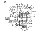
- Figure 1 is a longitudinal sectional view of a vane pump in one embodiment according to the present invention;
- Figure 2 is an enlarged side view of a pump section incorporated in the vane pump as viewed from the right in Figure 1;
- Figure 3 is an enlarged side view of a side plate in the embodiment as viewed from the right in Figure 1; and
- Figure 4 is an enlarged side view of another side plate used in a prior art corresponding to that shown in Figure 3.
-
- A vane pump in one embodiment according to the present invention will be described hereinafter with reference to Figures 1 through 3. The vane pump in this particular embodiment is of the type that a
side plate 20 and avane pump section 30 are piled up on each other to be stored within apump housing 10. Thepump housing 10 is composed of afront housing 11 having a stepped,cylindrical cave 11 a therein and arear housing 12 secured by means of bolts (not shown) to thefront housing 11 to fluid-tightly cover up an opening end of thecave 11 a. Inside thecave 11 a, theside plate 20 and thevane pump section 30 are plied up and housed respectively at the bottom portion and the opening end portion. The axial opposite ends of thevane pump section 30 are closed with theside plate 20 and therear housing 12 which are kept in abutting engagement therewith to constitute side wall members for thevane pump section 30. Inside thehousing 10, apump shaft 35 is also arranged coaxially with thecave 11 a and is rotatably supported at axial opposite end portions thereof by means of bearings (not numbered), which are provided respectively in thefront housing 11 and therear housing 12. - As best shown in Figures 2 and 3, the
vane pump section 30 is composed of acam ring 31 snugly fit and supported in thecave 11 a of thefront housing 11 and having acam surface 31 a of a generally elliptical shape at an internal surface thereof, arotor 32 connected coaxially on the axial mid portion of thepump shaft 35 through a spline engagement and having a plurality ofslits 32a arranged at the outer circumferential portion thereof at regular angular intervals to extend radially, and a plurality ofvanes 33 respectively received in theslits 32a to be movable radially. Thevanes 33 are brought into sliding contacts at radial outer ends thereof with thecam surface 31 a of thecam ring 31, so that eachvane 33 is radially moved to follow thecam surface 31 a upon rotation of therotor 32. Thevanes 33 partition a space between the outer circumferential surface of therotor 32 and thecam surface 31 a into a plurality of pump chambers (P) each of which is varied in volume as therotor 32 rotates. Thecam ring 31, together with theside plate 20, is positioned by means of positioning pins (not shown) on thehousing 10 not to be rotated relative thereto. Therotor 32 and thevanes 33 are slidable on inside end surfaces of therear housing 12 and theside plate 20. - As best shown in Figure 3, the
side plate 20 has formed a pair of horizontally spacedsuction ports 21 and another pair of vertically spacedejection ports 22 on the inside end surface on which thevanes 33 are slidable. Further, theside plate 20 has formed anannular backpressure groove 25 at its center portion to encircle a throughbore 20a which thepump shaft 35 passes through. Eachsuction port 21 is formed at the outer circumferential portion on the inside end surface of theside plate 20 to elongate circumferentially within an angular range or area (i.e., expansion area) where thevanes 33 move radially outwardly to increase the volume of each pump chamber (P) as therotor 32 rotates. Thesuction ports 21 are in communication with asuction hole 13a through asuction passage 13 formed in thehousing 10. Eachejection port 22 is formed on the inside end surface of theside plate 20 to elongate circumferentially within another angular range or area (i.e., compression area) where thevanes 33 move radially inwardly to decrease the volume of each pump chamber (P) as therotor 32 rotates. Eachejection portion 22 is in communication with apressure chamber 14 which is formed at the bottom end portion of thecave 11a located behind theside plate 20, through apassage 22a formed in theside pate 20 and is further in communication with an ejection bore through an ejection passage (both not shown) formed in thehousing 10. Eachejection port 22 elongates in the form of an arc shape and, at a rotationally following end thereof as therotor 32 rotates, is formed with awhisker groove 22b tiny in cross-section for preventing the drive torque fluctuation and the noise which are caused by the temporal increase in the pressure in the pump chambers (P). - The
backpressure groove 25 is arranged to communicate with radial innermost end portions of theslits 32a. As shown in Figures 2 and 3, thegroove 25 comprises a pair of right and leftsuction backpressure grooves 26, a pair of upper and lowerejection backpressure grooves 27,communication grooves 28, and a pair of cutout orrecess portions 29. Each of thesuction backpressure grooves 26 is generally arc and large in radial width and is arranged at the same angular phase as a corresponding one of thesuction ports 21 and between the same and the throughbore 20a in radial direction. Similarly, each of the ejection backpressuregrooves 27 is generally arc and large in radial width and is arranged at the same angular phase as a corresponding one of theejection ports 22 and between the same and the throughbore 20a in radial direction. Each of thecommunication grooves 28 takes the shape of a slender arc and makes eachsuction backpressure groove 26 communicate with each ejection backpressuregroove 27. Each of therecess portions 29 is arranged to cover an angular area where eachvane 33 rotating with therotor 32 is kept as being protruded to an outermost radial position, and extends radially outwardly from each ejection backpressuregroove 27 and thecommunication groove 28 behind the same in the rotational direction of therotor 32. That is, the angular area covers almost an pre-compression area and a compression area. Thus, as eachvane 33 is moved radially in theslit 32a therefor, the operating oil flows between the innermost end portion of theslit 32a and thebackpressure groove 25. The axial depth and radial width of each of the suction and ejection backpressuregrooves grooves communication groove 28 is made narrower in radial width than those of thebackpressure grooves backpressure grooves recess portion 29 is the same or less than the axial depth of eachcommunication groove 28. - Next, the shapes of the ejection backpressure
grooves 27 and therecess portions 29 will be described in grater detail with reference to Figures 2 and 3. The two-dotted chain line (L) in Figure 3 indicates a locus on which the radial innermost end of eachvane 33 moves when rotated with therotor 32. Like thecam surface 31 a of thecam ring 31, the locus (L) takes a generally ellipse shape whose radius decreases in the angular area (i.e., compression area) where eachvane 33 is moved radially inwardly as therotor 32 rotates and increases in the angular area (i.e., expansion area) where eachvane 33 is moved radially outwardly. The inner circumferential edge of each ejection backpressuregroove 27 taking an almost arc shape draws an arc with a center on the rotational axis of thepump shaft 35 as does that in the prior art vane pump shown in Figure 4. On the other hand, the outer circumferential edge of each ejection backpressuregroove 27 draws an arc with a center on the rotational axis of thepump shaft 35 within an angular area of about one-third which is behind in the rotational direction of therotor 32, but draws a curve which is reflected along the aforementioned locus (L) slightly radial outside of the same, that is, in parallel to the aforementioned locus (L) thereby to be indented toward the rotational axis of thepump shaft 35 in another area of about the remaining two-third which precedes in the rotational direction of therotor 32. Thus, within the compression angular area or, in particular, the rotationally preceding two-third angular area where eachvane 33 is moved radially inwardly, eachvane 33 is prevented from protruding the radial innermost end thereof radially inwardly beyond a predetermined distance from the outer circumferential edge of each ejection backpressuregroove 27. - Further, in order to shorten the length over which each vane 33 contacts the inside end surface of the
side plate 20, each of the cutout orrecess portions 29 is formed to extend radially outwardly from each ejection backpressuregroove 27 and eachcommunication groove 28 behind rotationally within an angular area which begins from a position slightly ahead of the rotationally preceding end of eachsuction backpressure groove 26 and which ends at the rotationally preceding end portion of each ejection backpressuregroove 27. At almost all the part except for a part preceding in the rotational direction of therotor 32, the outer circumferential edge of eachrecess portion 29 makes an arc which has a radius slightly larger than the long radius of the locus (L) with respect to a center on the rotational axis of thepump shaft 35. At the part preceding in the rotational direction of therotor 32, however, the outer circumferential edge of eachrecess portion 29 extends in parallel to the locus (L) which the radial innermost end of eachvane 32 draws and slightly outside of the locus (L) thereby to be indented toward the rotational axis of thepump shaft 35. Thus, the radial innermost end of eachvane 33, when the same is moved radially inwardly, is prevented from protruding radially inwardly beyond the predetermined distance from the outer circumferential edge of eachrecess portion 29 and is smoothly connected to the outer circumferential edge of each ejection backpressuregroove 27 within the almost two-third angular area ahead in the rotational direction of therotor 32. - The radius of the outer circumferential edge of each
recess portion 29 is so chosen that a reliable sealing capability is secured on a part of the flat inside end surface of theside plate 20 which part is left between therecess portion 29 and thewhisker groove 22b of theejection port 22 for sliding contact with the side surface of therotor 32. Further, the foregoing predetermined distance corresponds to the amount through which eachvane 33 is indented radially inwardly from the outer circumferential edge of eachrecess portion 29 at the part behind in the rotational direction of therotor 32 and from the outer circumferential edge of each ejection backpressuregroove 27 at the part ahead in the rotational direction of therotor 32. The predetermined distance is chosen so that a value which is necessary and sufficient to perform the function of guiding and supporting thevanes 3 is secured as the radial width of an guide area (d) which is formed on the inside surface of theside plate 20 between the rotationally preceding and radially indented part, which is common to the outer circumferential edges of each ejection backpressuregroove 27 and eachrecess portion 29, and the inner circumferential edge of eachejection port 22 for guiding the side surface of eachvane 33. - The
rear housing 12 closes the side surface of thevane pump section 30 at the opposite side of theside plate 20. Primarily for pressure balance, a pair of suction ports, a pair of ejection ports and a backpressure groove which is composed of suction and ejection backpressure grooves, communication grooves and recess portions are formed on an inside end surface of therear housing 12 in the same manner as, and symmetrically of, those formed on the inside end surface of theside plate 20. A guide area corresponding to that indicated at (d) on theside plate 20 is formed on the inside end surface of therear housing 12 between each ejection backpressure groove and each ejection port. The suction ports formed on therear housing 12 communicate with thesuction passage 13, while the ejection ports and the backpressure groove formed on therear housing 12 do not communicate with the exterior of thehousing 11. - The operation of the embodiment as constructed above will be described hereinafter. Since the
side plate 20 and therear housing 12 have substantially the same functions in guiding the end surfaces of therotor 32 and thevanes 33, the following description concerning the operation of the embodiment will be referred mainly to theside plate 20 unless particularly referred to on the contrary. - When the
rotor 32 is rotated bodily with thepump shaft 35, thevane 33 guided in eachslit 32a is reciprocated radially as the radial outmost end thereof is slidden along thecam surface 31a of thecam ring 31. Within the expansion angular area where eachvane 33 is moved radially outwardly, the operating oil flown from thesuction hole 13a is sucked from thesuction ports 21 into each pump chamber (P) whose volume is increasing. Within the compression angular area where eachvane 33 is moved radially inwardly, the operating oil within each pump chamber (P) whose volume is decreasing is ejected from each of theejection ports 22 through the ejection passage (not shown) to a suitable fluid-operated actuator, such as for example an automotive power steering device. The force by which eachvane 33 rotating with therotor 32 is urged to move radially inwardly is generated as a result that the radial outermost end of eachvane 33 protruding from therotor 32 is slidden on each slanted part of thecam surface 31 a at the internal surface of thecam ring 31 against the friction force and therefore irregularly fluctuates in terms of time and place because it is likely to be accompanied by self-induced vibration. However, in this particular embodiment, each of the guide areas (d) at diametrically opposite sides is formed on the inside end surface of each of theside plate 20 and therear housing 12 between eachejection port 22 and each ejection backpressuregroove 27 and the associatedrecess portion 29 thereby to guide and support the side surface of eachvane 33. And, each guide area (d) is chosen to have the radial width which is necessary and sufficient to perform the function of guiding and supporting eachvane 33. This can be done by directing or deflecting the rotationally preceding part common to the outer circumferential edges of each ejection backpressuregroove 27 and the associatedrecess portion 29 toward the rotational axis of therotor 32 to be indented along or in parallel to the locus (L) which eachvane 33 draws at its radial innermost end. Thus, eachvane 33 does not tend to incline on the guide areas (d). Accordingly, even if the force that urges eachvane 33 to move radially inwardly is that which irregularly fluctuates in terms of time and place, it does not occur that eachvane 33 is inclined on each guide area (d) to scrape against the same. This ensures that eachvane 33 moves smoothly and stably, so that thecam ring 31 does not suffer notable abrasion at thecam surface 31 a. Further, pulsation is hardly generated in the pump ejected pressure, nor does noise increase in the pump operation. - In the foregoing embodiment, the present invention is applied to the vane pump of the type that the
backpressure groove 25 is provided with therecess portions 29 for enabling thevanes 33 to protrude quickly form the circumferential surface of therotor 32 at the operation start of the pump. In this case, the advantage is particularly notable because the radial width of the guide area (d) which is formed between eachejection port 22 and theejection backpressure groove 27 and the associatedrecess portion 29 is largely increased compared with that in the prior art vane pump wherein as shown in Figure 4, the rotationally preceding part of the outer circumferential edge of eachsuch recess portion 6 is not directed or deflected to be indented toward the rotor rotational axis in parallel to the locus (L) which is followed by the innermost end of each vane. - However, the application of the present invention is not limited to the vane pump with
such recess portions 29. Rather, the present invention may be applied to a modified vane pump that is constituted by omitting therecess portions 6 from the prior art vane pump whose side plate 1 is shown in Figure 4. In this modified vane pump, by deflecting the rotationally preceding part of the outer circumferential edge of each ejection backpressuregroove 27 to be indented toward the rotor rotational axis in parallel to the locus (L) drawn by the radial innermost end of eachvane 33 in the same manner as the foregoing embodiment, the radial width which is formed between theejection port 22 and theejection backpressure groove 27 can be enlarged compared to that (e) of the prior art pump wherein as shown in Figure 4, the rotationally preceding part of the outer circumferential edge of each ejection backpressuregroove 4 is not indented toward the rotor rotational axis. Thus, the movement of eachvane 33 in the modified vane pump is smoothened and stabled, so that substantially the same effect as in the foregoing embodiment can be attained even in the modified vane pump. - In addition, the present invention may be applied to a further modified vane pump wherein the
backpressure groove 25 is constituted to have the same cross-section as the suction backpressure grooves 26 (or the ejection backpressure grooves 27) over the entire circumferential length thereof. In this further modified vane pump, a part of thebackpressure groove 25 within an angular area corresponding to eachejection port 22 is deflected to be indented toward the rotor rotational axis along or in parallel to the aforementioned locus (L). Thus, the further modified vane pump can have an enlarged radial width at the guide area which is formed between eachejection port 22 and the radially inwardly indented part of the backpressure groove, and the movement of eachvane 33 becomes stable to attain substantially the same effect as is attained in the foregoing embodiment. - Although in the illustrated embodiment, the outer circumferential edges of each ejection backpressure
groove 27 and the associatedrecess portion 29 define a single, common rotationally preceding part thereof which is deflected to be indented toward the rotor rotational axis along or in parallel to the aforementioned locus (L), they may define individual rotationally preceding parts thereof each of which is deflected to be indented toward the rotor rotational axis along or in parallel to the aforementioned locus (L), - Moreover, the rotationally preceding part along the aforementioned locus (L) of each ejection backpressure
groove 27 in the illustrated embodiment or of thebackpressure groove 25 in the further modified embodiment may extend in parallel to the aforementioned locus (L) slightly radial outside of the same as shown in Figure 3 or may strictly follow the aforementioned locus (L) to trace the same. The same is true with the rotationally preceding part along the aforementioned locus (L) of eachrecess portion 29. - Furthermore, the part indented along the aforementioned locus (L) of each ejection backpressure
groove 27, of thebackpressure groove 25 or of eachrecess portion 29 may be formed on the inside end surface of any one of theside plate 20 and therear housing 12, but not on the inside end surface of the other. - Finally, various features and many of the attendant advantages in the foregoing embodiment will be summarized as follows:
- In one aspect of the forgoing embodiment, as typically shown in Figure 1, within the angular area where each of the
vanes 33 is moved radially inwardly while being rotated together with therotor 32, the outer circumferential edge of thebackpressure groove 25 is deflected to be indented toward the rotational axis of therotor 32 along the locus (L) so that the radial innermost end of eachvane 33 is prevented from protruding radially inwardly beyond the predetermined distance from the outer circumferential edge of thebackpressure groove 25. Thus, the radial width of a guide area (d) on the inside end surface of a side wall member 20 (or 12) which slidably guides one side surface of eachvane 33 when the same is moved radially is enlarged by the portion indented toward the rotational axis of therotor 32. Therefore, since the vane guide function of the inside end surface of the side wall member 20 (or 12) is ensured, the radially inward movement of eachvane 33 within the aforementioned angular area can be stabilized and smoothened compared to that in the prior art. Consequently, thecam surface 31 a at the internal surface of thecam ring 31 does not suffer notable abrasion, and pulsation is hardly generated in the pump ejection pressure, nor does noise increase in the pump operation. - In another aspect of the forgoing embodiment, the
backpressure groove 25 is composed of thesuction backpressure groove 26 within each expansion angular area, theejection backpressure groove 27 within each compression angular area and thecommunication grooves 28 connecting the suction and ejection backpressuregrooves backpressure groove 25. In this modified vane pump, the outer circumferential edge of theejection backpressure groove 27 is deflected at a rotationally preceding part thereof to be indented toward the rotational axis of therotor 32 along the locus (L) so that the radial innermost end of eachvane 33 being moved radially inwardly is prevented from protruding radially inwardly beyond the predetermined distance from the outer circumferential edge of theejection backpressure groove 27. Thus, the radial width of each guide area (d) on the inside end surface of the side wall member 20 (or 12) which slidably guides one side surface of eachvane 33 when the same is moved radially is enlarged by the area which is indented toward the rotational axis of therotor 32. Therefore, since the vane guide function of the inside end surface of the side wall member 20 (or 12) is ensured, the radially inward movement of eachvane 33 within the aforementioned angular area can be stabilized and smoothened compared to that in the prior art. Consequently, thecam surface 31a at the internal surface of thecam ring 31 does not suffer notable abrasion, and pulsation is hardly generated in the pump ejection pressure, nor does noise increase in the pump operation. - In a further aspect of the forgoing embodiment, within at least a part of another angular area where each
vane 33 is moved radially inwardly from the radial outermost position, therecess portion 29 for preventing the radial innermost part of the side end surface of eachvane 33 from contacting the inside end surface of the side wall member 20 (or 12) is further provided on the inside end surface of the side wall member 20 (or 12) which slidably contact therotor 32 and eachvane 33. As a result, the length that the side surface of eachvane 33 contacts the inside end surface of the side wall member 20 (or 12) is further shortened, and this reduces the sliding resistance against eachvane 33, so that the same can be enabled to protrude quickly from therotor 32 at the operation start of the vane pump. In addition, the outer circumferential edge of therecess portion 29 is deflected at its rotationally preceding part to be indented toward the rotational axis of therotor 32 along the locus (L) so that the radial innermost end of eachvane 33 does not protrude radially inwardly beyond the predetermined distance from the outer circumferential edge of therecess portion 29. Thus, the radial width of the guide area (d) on the inside end surface of the side wall member 20 (or 12) which slidably guides one side surface of eachvane 33 when the same is moved radially is enlarged by the portion indented toward the rotational axis of therotor 32. Therefore, although the contact length of the vane side surface with the inside end surface of the side wall member 20 (or 12) is shortened by the provision of therecess portion 29, the radially inward movement of eachvane 33 within the aforementioned angular area can be stabilized and smoothened compared to that in the prior art since the vane guide function of the inside end surface of the side wall member 20 (or 12) is ensured. Consequently, thecam surface 31 a at the internal surface of thecam ring 31 does not suffer notable abrasion, and pulsation is hardly generated in the pump ejection pressure, nor does noise increase in the pump operation. - Obviously, numerous modifications and variations of the present invention are possible in light of the above teachings. It is therefore to be understood that within the scope of the appended claims, the present invention may be practiced otherwise than as specifically described herein.
- Disclosed is a vane pump capable of decreasing abrasion at a cam surface at the internal surface of a cam ring, pulsation in pump ejected pressure and noise in pump operation. The vane pump is provided with a vane pump section which includes a cam ring rotatably receiving therein a rotor which has a plurality of slits formed radially. Vanes are radially slidably received respectively in the slits to be rotated bodily with the rotor with radial outermost ends sliding on the cam surface. Axial opposite end surfaces of the vane pump section are closed by side wall members, and a backpressure groove which is supplied with the pump ejection pressure in communication with radial innermost end portions of the slits is formed on an inside end surface of each side wall member to encircle the rotational axis of the rotor. Within an angular area where each vane is moved radially inwardly as the rotor rotates, the outer circumferential edge of the backpressure groove is deflected to be indented toward the rotational axis of the rotor along a locus drawn by the radial innermost end of each vane so that the radial innermost end of each vane being rotated does not protrude radially inwardly beyond a predetermined distance from the indented part of the outer circumferential edge of the backpressure groove.
Claims (7)
- A vane pump comprising:a vane pump section composed of a cam ring contained in a pump housing, a rotor rotatably provided in said cam ring with a plurality of slits formed in radial direction, and a plurality of vanes guided to be radially slidable respectively in said slits and brought at radial outermost ends into sliding engagement with a cam surface formed at the internal surface of said cam ring for partitioning a space between the outer circumferential surface of said rotor and said cam surface into plural pump chambers each of which is varied in volume as said rotor rotates;at least one side wall member closing at least one side surface of said vane pump section and enabling said rotor and said vanes to be slidable thereon; andan annular backpressure groove formed on an inside end surface of said side wall member to encircle the rotational axis of said rotor to communicate with innermost end portions of said slits and supplied with pressurized fluid ejected from said pump, wherein within an angular area where each vane is moved radially inwardly while being rotated together with said rotor, the outer circumferential edge of said backpressure groove is deflected to be indented toward the rotational axis of said rotor along a locus on which the radial innermost end of each vane moves so that the radial innermost end of each vane does not protrude radially inwardly beyond a predetermined distance from the indented part of the outer circumferential edge of said backpressure groove.
- The vane pump as set forth in Claim 1, wherein said backpressure groove comprising:wherein the outer circumferential edge of said ejection backpressure groove is deflected at its rotationally preceding part to be indented toward the rotational axis of said rotor along said locus so that the radial innermost end of each vane does not protrude radially inwardly beyond said predetermined distance from the rotationally preceding part of the outer circumferential edge of said ejection backpressure groove.at least one suction backpressure groove arranged to be circumferentially close to at least one suction port which opens to said pump chambers within an angular area where each of said pump chambers increases its volume as said rotor rotates;at least one ejection backpressure groove arranged to be circumferentially close to at least one ejection port which opens to said pump chambers within another angular area where each of said pump chambers decreases its volume as said rotor rotates; andcommunication grooves of an arc shape having a center on the rotational axis of said rotor and connecting said at least one suction backpressure groove with said at least one ejection backpressure groove; and
- The vane pump as set forth in Claim 1, wherein:within at least a part of another angular area where each vane is moved radially inwardly from the radial outermost position, a recess portion for preventing a radial innermost part of one side surface of each vane from contacting the inside end surface of said side wall member is further provided on the inside end surface of said side wall member which slidably contacts said rotor and each vane; andthe outer circumferential edge of said recess portion is deflected at its rotationally preceding part to be indented toward the rotational axis of said rotor along said locus so that the radial innermost end of each vane does not protrude radially inwardly beyond a predetermined distance from the rotationally preceding part of the outer circumferential edge of said recess portion.
- The vane pump as set forth in Claim 2, wherein:within at least a part of another angular area where each vane is moved radially inwardly from the radial outermost position, a recess portion for preventing a radial innermost part of one side surface of each vane from contacting the inside end surface of said side wall member is further provided on the inside end surface of said side wall member which slidably contacts said rotor and each vane; andthe outer circumferential edge of said recess portion is deflected at its rotationally preceding part to be indented toward the rotational axis of said rotor along said locus so that the radial innermost end of each vane does not protrude radially inwardly beyond a predetermined distance from the rotationally preceding part of the outer circumferential edge of said recess portion.
- The vane pump as set forth in Claim 4, wherein the rotationally preceding part of the outer circumferential edge of said recess portion is in parallel to said locus.
- The vane pump as set forth in Claim 2, wherein the rotationally preceding part of the outer circumferential edge of said ejection backpressure groove is in parallel to said locus.
- The vane pump as set forth in Claim 3, wherein the rotationally preceding part of the outer circumferential edge of said recess portion is in parallel to said locus.
Applications Claiming Priority (2)
| Application Number | Priority Date | Filing Date | Title |
|---|---|---|---|
| JP2003105286A JP4193554B2 (en) | 2003-04-09 | 2003-04-09 | Vane pump |
| JP2003105286 | 2003-04-09 |
Publications (2)
| Publication Number | Publication Date |
|---|---|
| EP1467101A1 true EP1467101A1 (en) | 2004-10-13 |
| EP1467101B1 EP1467101B1 (en) | 2012-06-27 |
Family
ID=32866743
Family Applications (1)
| Application Number | Title | Priority Date | Filing Date |
|---|---|---|---|
| EP04008629A Expired - Lifetime EP1467101B1 (en) | 2003-04-09 | 2004-04-08 | Vane pump |
Country Status (3)
| Country | Link |
|---|---|
| US (1) | US6877969B2 (en) |
| EP (1) | EP1467101B1 (en) |
| JP (1) | JP4193554B2 (en) |
Cited By (4)
| Publication number | Priority date | Publication date | Assignee | Title |
|---|---|---|---|---|
| WO2009121470A1 (en) * | 2008-04-04 | 2009-10-08 | Ixetic Bad Homburg Gmbh | Pump, particularly vane pump |
| CN110374875A (en) * | 2019-07-29 | 2019-10-25 | 珠海格力节能环保制冷技术研究中心有限公司 | Slide vane structure, rotor-type compressor and the refrigeration equipment of rotor-type compressor |
| EP3081741B1 (en) | 2015-04-17 | 2019-11-13 | Schwäbische Hüttenwerke Automotive GmbH | Pump |
| CN111373150A (en) * | 2017-11-20 | 2020-07-03 | Kyb株式会社 | Vane pump |
Families Citing this family (14)
| Publication number | Priority date | Publication date | Assignee | Title |
|---|---|---|---|---|
| DE102004060551A1 (en) * | 2004-12-16 | 2006-06-22 | Robert Bosch Gmbh | Vane pump |
| US7628596B2 (en) * | 2006-09-22 | 2009-12-08 | Ford Global Technologies, Llc | Power steering pump |
| JP5395713B2 (en) * | 2010-01-05 | 2014-01-22 | 日立オートモティブシステムズ株式会社 | Vane pump |
| JP2011149334A (en) * | 2010-01-21 | 2011-08-04 | Showa Corp | Hydraulic control device for vehicle |
| US20110293460A1 (en) * | 2010-05-26 | 2011-12-01 | Sara Dexter | Vane pump inlet window shape |
| JP5514068B2 (en) * | 2010-10-22 | 2014-06-04 | カヤバ工業株式会社 | Vane pump |
| JP5865631B2 (en) * | 2011-08-23 | 2016-02-17 | 株式会社ショーワ | Vane pump |
| US8540500B1 (en) | 2012-05-08 | 2013-09-24 | Carl E. Balkus, Jr. | High capacity lightweight compact vane motor or pump system |
| CN106050658B (en) * | 2012-05-21 | 2020-10-20 | 纳博特斯克汽车零部件有限公司 | Vacuum pump |
| JP6122659B2 (en) | 2013-02-26 | 2017-04-26 | Kyb株式会社 | Vane pump |
| JP6329775B2 (en) * | 2014-01-27 | 2018-05-23 | Kyb株式会社 | Vane pump |
| CN107735574B (en) * | 2015-06-02 | 2020-08-14 | 翰昂汽车零部件德国有限公司 | Vane pump and method for operating the same |
| US9920666B2 (en) | 2015-09-29 | 2018-03-20 | Ford Global Technologies, Llc | Vane oil pump |
| DE102019127388A1 (en) * | 2019-10-10 | 2021-04-15 | Schwäbische Hüttenwerke Automotive GmbH | Fluid supply of under vane chambers of a vane pump |
Citations (2)
| Publication number | Priority date | Publication date | Assignee | Title |
|---|---|---|---|---|
| US6203303B1 (en) | 1998-12-11 | 2001-03-20 | Toyoda Koki Kabushiki Kaisha | Vane pump |
| US6244830B1 (en) | 1996-12-23 | 2001-06-12 | Luk, Fahrzeug-Jydraulik Gmbh & Co. Kg | Vane-cell pump |
Family Cites Families (2)
| Publication number | Priority date | Publication date | Assignee | Title |
|---|---|---|---|---|
| US4386891A (en) * | 1981-04-23 | 1983-06-07 | General Motors Corporation | Rotary hydraulic vane pump with undervane passages for priming |
| JPH1089266A (en) * | 1996-09-17 | 1998-04-07 | Toyoda Mach Works Ltd | Vane pump |
-
2003
- 2003-04-09 JP JP2003105286A patent/JP4193554B2/en not_active Expired - Fee Related
-
2004
- 2004-04-07 US US10/819,290 patent/US6877969B2/en not_active Expired - Lifetime
- 2004-04-08 EP EP04008629A patent/EP1467101B1/en not_active Expired - Lifetime
Patent Citations (2)
| Publication number | Priority date | Publication date | Assignee | Title |
|---|---|---|---|---|
| US6244830B1 (en) | 1996-12-23 | 2001-06-12 | Luk, Fahrzeug-Jydraulik Gmbh & Co. Kg | Vane-cell pump |
| US6203303B1 (en) | 1998-12-11 | 2001-03-20 | Toyoda Koki Kabushiki Kaisha | Vane pump |
Cited By (5)
| Publication number | Priority date | Publication date | Assignee | Title |
|---|---|---|---|---|
| WO2009121470A1 (en) * | 2008-04-04 | 2009-10-08 | Ixetic Bad Homburg Gmbh | Pump, particularly vane pump |
| EP3081741B1 (en) | 2015-04-17 | 2019-11-13 | Schwäbische Hüttenwerke Automotive GmbH | Pump |
| CN111373150A (en) * | 2017-11-20 | 2020-07-03 | Kyb株式会社 | Vane pump |
| CN111373150B (en) * | 2017-11-20 | 2022-03-22 | Kyb株式会社 | Vane pump |
| CN110374875A (en) * | 2019-07-29 | 2019-10-25 | 珠海格力节能环保制冷技术研究中心有限公司 | Slide vane structure, rotor-type compressor and the refrigeration equipment of rotor-type compressor |
Also Published As
| Publication number | Publication date |
|---|---|
| JP2004308605A (en) | 2004-11-04 |
| US20040202565A1 (en) | 2004-10-14 |
| JP4193554B2 (en) | 2008-12-10 |
| EP1467101B1 (en) | 2012-06-27 |
| US6877969B2 (en) | 2005-04-12 |
Similar Documents
| Publication | Publication Date | Title |
|---|---|---|
| US6877969B2 (en) | Vane pump | |
| US6544021B2 (en) | Oil pump | |
| EP0829643A1 (en) | Vane type rotary pump | |
| KR101520526B1 (en) | Vane rotary compressor | |
| US11732712B2 (en) | Rotary compressor | |
| US7566211B2 (en) | Vane pump having vanes with a cutout portion | |
| US7628594B2 (en) | Vane pump having a labyrinth seal and gap between a top surface of a rotor and a ceiling surface of a rotor chamber that is formed between upper and lower cases | |
| US20230175504A1 (en) | High pressure variable vane pump with vane pins | |
| US5026263A (en) | Rotary vane pump with valve to control vane biassing | |
| JPH11257247A (en) | Roller vane pump | |
| US10767645B2 (en) | Fuel pump | |
| US6135742A (en) | Eccentric-type vane pump | |
| JP3813783B2 (en) | Vane pump | |
| KR970062340A (en) | Rotor type pump | |
| US6599111B2 (en) | Vane pump having an intake groove through a side wall member | |
| JP6421747B2 (en) | Compressor | |
| US20160017884A1 (en) | Variable displacement vane pump | |
| JP2003184759A (en) | Vane pump | |
| CN214887511U (en) | Piston assembly and hydraulic rotary device provided with same | |
| US11193484B2 (en) | Automotive liquid pendulum vane pump | |
| JP2846340B2 (en) | Variable displacement vane oil pump | |
| JP2582863Y2 (en) | Vane pump | |
| US4886436A (en) | Lubricating arrangement for a shaft seal in a vane type compressor | |
| JP2003097453A (en) | Variable displacement vane pump | |
| JP4410528B2 (en) | Variable displacement vane pump |
Legal Events
| Date | Code | Title | Description |
|---|---|---|---|
| PUAI | Public reference made under article 153(3) epc to a published international application that has entered the european phase |
Free format text: ORIGINAL CODE: 0009012 |
|
| AK | Designated contracting states |
Kind code of ref document: A1 Designated state(s): AT BE BG CH CY CZ DE DK EE ES FI FR GB GR HU IE IT LI LU MC NL PL PT RO SE SI SK TR |
|
| AX | Request for extension of the european patent |
Extension state: AL HR LT LV MK |
|
| 17P | Request for examination filed |
Effective date: 20050318 |
|
| AKX | Designation fees paid |
Designated state(s): DE FR GB |
|
| RAP1 | Party data changed (applicant data changed or rights of an application transferred) |
Owner name: JTEKT CORPORATION |
|
| RIN1 | Information on inventor provided before grant (corrected) |
Inventor name: YAMAUCHI, KENTARO Inventor name: YAO, HIROYUKI Inventor name: FUJIWARA, HIDETOSHI |
|
| 17Q | First examination report despatched |
Effective date: 20071001 |
|
| GRAP | Despatch of communication of intention to grant a patent |
Free format text: ORIGINAL CODE: EPIDOSNIGR1 |
|
| GRAS | Grant fee paid |
Free format text: ORIGINAL CODE: EPIDOSNIGR3 |
|
| GRAA | (expected) grant |
Free format text: ORIGINAL CODE: 0009210 |
|
| RBV | Designated contracting states (corrected) |
Designated state(s): DE FR |
|
| AK | Designated contracting states |
Kind code of ref document: B1 Designated state(s): DE FR |
|
| REG | Reference to a national code |
Ref country code: DE Ref legal event code: R096 Ref document number: 602004038350 Country of ref document: DE Effective date: 20120816 |
|
| PLBE | No opposition filed within time limit |
Free format text: ORIGINAL CODE: 0009261 |
|
| STAA | Information on the status of an ep patent application or granted ep patent |
Free format text: STATUS: NO OPPOSITION FILED WITHIN TIME LIMIT |
|
| 26N | No opposition filed |
Effective date: 20130328 |
|
| REG | Reference to a national code |
Ref country code: DE Ref legal event code: R097 Ref document number: 602004038350 Country of ref document: DE Effective date: 20130328 |
|
| REG | Reference to a national code |
Ref country code: FR Ref legal event code: PLFP Year of fee payment: 13 |
|
| REG | Reference to a national code |
Ref country code: FR Ref legal event code: PLFP Year of fee payment: 14 |
|
| REG | Reference to a national code |
Ref country code: FR Ref legal event code: PLFP Year of fee payment: 15 |
|
| PGFP | Annual fee paid to national office [announced via postgrant information from national office to epo] |
Ref country code: FR Payment date: 20200312 Year of fee payment: 17 |
|
| PGFP | Annual fee paid to national office [announced via postgrant information from national office to epo] |
Ref country code: DE Payment date: 20200325 Year of fee payment: 17 |
|
| REG | Reference to a national code |
Ref country code: DE Ref legal event code: R119 Ref document number: 602004038350 Country of ref document: DE |
|
| PG25 | Lapsed in a contracting state [announced via postgrant information from national office to epo] |
Ref country code: FR Free format text: LAPSE BECAUSE OF NON-PAYMENT OF DUE FEES Effective date: 20210430 Ref country code: DE Free format text: LAPSE BECAUSE OF NON-PAYMENT OF DUE FEES Effective date: 20211103 |