EP1466873A2 - Glass preform for an optical fiber and manufacturing method thereof - Google Patents
Glass preform for an optical fiber and manufacturing method thereof Download PDFInfo
- Publication number
- EP1466873A2 EP1466873A2 EP04090123A EP04090123A EP1466873A2 EP 1466873 A2 EP1466873 A2 EP 1466873A2 EP 04090123 A EP04090123 A EP 04090123A EP 04090123 A EP04090123 A EP 04090123A EP 1466873 A2 EP1466873 A2 EP 1466873A2
- Authority
- EP
- European Patent Office
- Prior art keywords
- optical fiber
- base material
- core rod
- glass base
- manufacturing
- Prior art date
- Legal status (The legal status is an assumption and is not a legal conclusion. Google has not performed a legal analysis and makes no representation as to the accuracy of the status listed.)
- Withdrawn
Links
Images



Classifications
-
- F—MECHANICAL ENGINEERING; LIGHTING; HEATING; WEAPONS; BLASTING
- F16—ENGINEERING ELEMENTS AND UNITS; GENERAL MEASURES FOR PRODUCING AND MAINTAINING EFFECTIVE FUNCTIONING OF MACHINES OR INSTALLATIONS; THERMAL INSULATION IN GENERAL
- F16B—DEVICES FOR FASTENING OR SECURING CONSTRUCTIONAL ELEMENTS OR MACHINE PARTS TOGETHER, e.g. NAILS, BOLTS, CIRCLIPS, CLAMPS, CLIPS OR WEDGES; JOINTS OR JOINTING
- F16B15/00—Nails; Staples
- F16B15/06—Nails; Staples with barbs, e.g. for metal parts; Drive screws
-
- C—CHEMISTRY; METALLURGY
- C03—GLASS; MINERAL OR SLAG WOOL
- C03B—MANUFACTURE, SHAPING, OR SUPPLEMENTARY PROCESSES
- C03B37/00—Manufacture or treatment of flakes, fibres, or filaments from softened glass, minerals, or slags
- C03B37/01—Manufacture of glass fibres or filaments
- C03B37/012—Manufacture of preforms for drawing fibres or filaments
- C03B37/014—Manufacture of preforms for drawing fibres or filaments made entirely or partially by chemical means, e.g. vapour phase deposition of bulk porous glass either by outside vapour deposition [OVD], or by outside vapour phase oxidation [OVPO] or by vapour axial deposition [VAD]
- C03B37/01466—Means for changing or stabilising the diameter or form of tubes or rods
-
- C—CHEMISTRY; METALLURGY
- C03—GLASS; MINERAL OR SLAG WOOL
- C03B—MANUFACTURE, SHAPING, OR SUPPLEMENTARY PROCESSES
- C03B37/00—Manufacture or treatment of flakes, fibres, or filaments from softened glass, minerals, or slags
- C03B37/01—Manufacture of glass fibres or filaments
- C03B37/012—Manufacture of preforms for drawing fibres or filaments
- C03B37/014—Manufacture of preforms for drawing fibres or filaments made entirely or partially by chemical means, e.g. vapour phase deposition of bulk porous glass either by outside vapour deposition [OVD], or by outside vapour phase oxidation [OVPO] or by vapour axial deposition [VAD]
- C03B37/01413—Reactant delivery systems
-
- F—MECHANICAL ENGINEERING; LIGHTING; HEATING; WEAPONS; BLASTING
- F16—ENGINEERING ELEMENTS AND UNITS; GENERAL MEASURES FOR PRODUCING AND MAINTAINING EFFECTIVE FUNCTIONING OF MACHINES OR INSTALLATIONS; THERMAL INSULATION IN GENERAL
- F16B—DEVICES FOR FASTENING OR SECURING CONSTRUCTIONAL ELEMENTS OR MACHINE PARTS TOGETHER, e.g. NAILS, BOLTS, CIRCLIPS, CLAMPS, CLIPS OR WEDGES; JOINTS OR JOINTING
- F16B15/00—Nails; Staples
- F16B15/0015—Staples
-
- F—MECHANICAL ENGINEERING; LIGHTING; HEATING; WEAPONS; BLASTING
- F16—ENGINEERING ELEMENTS AND UNITS; GENERAL MEASURES FOR PRODUCING AND MAINTAINING EFFECTIVE FUNCTIONING OF MACHINES OR INSTALLATIONS; THERMAL INSULATION IN GENERAL
- F16B—DEVICES FOR FASTENING OR SECURING CONSTRUCTIONAL ELEMENTS OR MACHINE PARTS TOGETHER, e.g. NAILS, BOLTS, CIRCLIPS, CLAMPS, CLIPS OR WEDGES; JOINTS OR JOINTING
- F16B15/00—Nails; Staples
- F16B15/08—Nails; Staples formed in integral series but easily separable
-
- C—CHEMISTRY; METALLURGY
- C03—GLASS; MINERAL OR SLAG WOOL
- C03B—MANUFACTURE, SHAPING, OR SUPPLEMENTARY PROCESSES
- C03B2201/00—Type of glass produced
- C03B2201/02—Pure silica glass, e.g. pure fused quartz
- C03B2201/03—Impurity concentration specified
- C03B2201/04—Hydroxyl ion (OH)
-
- C—CHEMISTRY; METALLURGY
- C03—GLASS; MINERAL OR SLAG WOOL
- C03B—MANUFACTURE, SHAPING, OR SUPPLEMENTARY PROCESSES
- C03B2201/00—Type of glass produced
- C03B2201/06—Doped silica-based glasses
- C03B2201/07—Impurity concentration specified
- C03B2201/075—Hydroxyl ion (OH)
-
- G—PHYSICS
- G02—OPTICS
- G02B—OPTICAL ELEMENTS, SYSTEMS OR APPARATUS
- G02B6/00—Light guides; Structural details of arrangements comprising light guides and other optical elements, e.g. couplings
- G02B6/02—Optical fibres with cladding with or without a coating
- G02B6/02004—Optical fibres with cladding with or without a coating characterised by the core effective area or mode field radius
-
- G—PHYSICS
- G02—OPTICS
- G02B—OPTICAL ELEMENTS, SYSTEMS OR APPARATUS
- G02B6/00—Light guides; Structural details of arrangements comprising light guides and other optical elements, e.g. couplings
- G02B6/02—Optical fibres with cladding with or without a coating
- G02B6/036—Optical fibres with cladding with or without a coating core or cladding comprising multiple layers
- G02B6/03616—Optical fibres characterised both by the number of different refractive index layers around the central core segment, i.e. around the innermost high index core layer, and their relative refractive index difference
- G02B6/03638—Optical fibres characterised both by the number of different refractive index layers around the central core segment, i.e. around the innermost high index core layer, and their relative refractive index difference having 3 layers only
-
- G—PHYSICS
- G02—OPTICS
- G02B—OPTICAL ELEMENTS, SYSTEMS OR APPARATUS
- G02B6/00—Light guides; Structural details of arrangements comprising light guides and other optical elements, e.g. couplings
- G02B6/02—Optical fibres with cladding with or without a coating
- G02B6/036—Optical fibres with cladding with or without a coating core or cladding comprising multiple layers
- G02B6/03694—Multiple layers differing in properties other than the refractive index, e.g. attenuation, diffusion, stress properties
Definitions
- the present invention relates to manufacturing a glass base material for an optical fiber. More particularly, the present invention relates to a glass base material for an optical fiber and a manufacturing method thereof, where the absorption by hydroxyl groups is reduced.
- wavelength which is about 1300 or 1550nm is being used.
- WDM Wavelength Division Multiplexing
- Fig. 1 shows the relation between transmission loss and wavelength in a general single-mode optical fiber.
- the transmission loss of a general optical fiber increases significantly at about 1385nm. If the transmission loss increases, transmission using the light of about 1385nm cannot be performed, the number of channels which can be used in, e.g. CWDM (Coarse-WDM) decreases, and thereby the entire transmission capacity decreases.
- CWDM Coarse-WDM
- the significant increase of the transmission loss at about 1385nm in wavelength is due to the absorption by hydroxyl groups contained in the optical fiber, where the increase occurs because hydroxyl groups vibrate and absorb light.
- the peak value of the absorption by hydroxyl groups can be obtained from the difference between the peak value of the transmission loss at about 1385nm in wavelength in Fig. 1 and the value of the transmission loss at about 1385nm in wavelength with regard to the graph shown as a dotted line when the transmission loss decreases gently. Furthermore, the peak value of the absorption by hydroxyl groups in Fig. 1 is approximately 0.1dB/km.
- a method for providing a glass base material for a single-mode optical fiber where hydroxyl groups are reduced is exemplified by Japanese Patent No. 3301602 using an over-jacketing method.
- hydroxyl groups are reduced by using plasma flame so as not to contaminate the glass rod with hydroxyl groups or eliminating the contaminated layer after drawing the rod with flame.
- a method of jacketing a hollow cylindrical tube has been generally known.
- glass particles are deposited directly over a glass rod including a core, and then dehydrated and converted into transparent glass.
- the cost is high. The reason is that shaping treatment or surface treatment is inevitable after the hollow cylindrical tube itself is manufactured by the OVD or VAD method.
- a method for manufacturing a glass base material for an optical fiber by forming a core rod having a core section and a portion of a clad, forming an additional clad by depositing glass particles on circumference of the core rod, and performing a sintering and vitrifying process on an obtained porous base material includes the step of forming the core rod in order that the relation 3.75 ⁇ a/m ⁇ 6 is satisfied, where 'a' denotes an outer diameter of a section corresponding to the core rod, and 'm' denotes a mode field diameter at 1385nm in wavelength with regard to the optical fiber obtained by drawing the glass base material.
- the core rod may be manufactured by using one of methods which are VAD, OVD, MCVD and PCVD.
- the average concentration of hydroxyl groups may be 1ppb or less in a section of the core rod equivalent to at least 90% of an outer diameter thereof.
- the average concentration of hydroxyl groups may be 50ppm or less in a section of the additional clad equivalent to at least 150% of an inner diameter thereof.
- a glass base material for an optical fiber is manufactured by the above method.
- an optical fiber is obtained by heating and drawing the above glass base material.
- a contribution portion of absorption loss caused by hydroxyl groups may be 0.04dB/km or less with regard to a transmission loss spectrum of the optical fiber at about 1385nm in wavelength.
- a method for manufacturing a glass base material for an optical fiber where transmission loss at 1385nm in wavelength caused by hydroxyl groups inside the optical fiber is reduced includes the steps of forming a core rod, further forming an additional clad on the circumference of the core rod in order that the following relation is satisfied: 3.75 ⁇ a/m ⁇ 6, where 'a' denotes the outer diameter of a section corresponding to the core rod, and 'm' denotes the mode field diameter at 1385nm in wavelength with regard to the optical fiber obtained by drawing theglassbasematerial, andperformingasinteringandvitrifying process.
- the optical fiber can be obtained by drawing the glass base material.
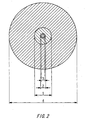
- Fig. 2 is a cross-sectional view of an optical fiber obtained by drawing a glass base material of the present invention.
- a core inside a section 1 corresponding to the core rod consisting of the core section and a portion of a clad and a mode field diameter 2 at 1385nm in wavelength is larger than a core diameter 3.
- hydroxyl groups caused by drawing the core rod with flame exist at a few to a few tens of ppm in density, since this area is distanced enough from the mode field diameter 2, the absorption peak by hydroxyl groups can be controlled, and the contaminated layer due to hydroxyl groups does not need to be eliminated.
- the symbol 4 represents the diameter of the optical fiber.
- the core rod is manufactured by one of the methods such as VAD, OVD, MCVD, PCVD, etc. Among them, it is the VAD method that is easy to reduce especially the content of hydroxyl groups, because no holes exist from the beginning of manufacturing a center section of the core rod until finishing the process. Since in all of the methods there exist holes in the center section of the core rod, it is necessary to be careful about reducing the content of hydroxyl groups.
- the average concentration of hydroxyl groups of the core rod is 1ppb or less in a portion equivalent to at least 90% of the outer diameter of the core rod, this concentration can be achieved relatively easily by manufacturing a porous base material for the core rod using the VAD method and performing a dehydrating process carefully on the obtained porous base material.
- an additional clad is added to the core rod, and the average concentration of hydroxyl groups of the additional clad is 50ppm or less in a portion equivalent to at least 150% of the inner diameter of the additional clad. That can be achieved easily by using the method described above of performing a dehydrating and vitrifying process after depositing glass particles on the circumference of the core rod.
- Fig. 3 shows an example of processes of manufacturing a glass base material for an optical fiber where the content of hydroxyl groups is small according to the present invention, in case of manufacturing a core rod by the VAD method.
- Burners 5 and 6 for core and clad respectively are supplied with glass raw materials as well as oxygen and hydrogen so as to form a glass particle flow 7, and then a porous base material 8 for a core rod is manufactured. Further, into the burner 5 for core a dopent for adjusting the index of refraction is introduced at the same time so as to form a section whose index of refraction is high.
- the outer diameter and the core diameter of the core rod obtained by dehydrating and vitrifying the porous base material 8 are controlled in order that the ratio of the outer diameter a of the section corresponding to the core rod to the mode field diameter m at 1385nm in wavelength satisfies the following relation: 3.75 ⁇ a/m ⁇ 6, with regard to an optical fiber to be obtained by drawing the glass base material.
- burner 6 for clad Although only one burner 6 for clad is shown in Fig. 3, two or more burners may be used for the necessary volume of the clad. With regard to the burner 5 for core, two or more burners can be used for a complicated profile such as a stair or segment type other than a general step index type.
- the porous base material 8 obtained in such way is passed through a furnace 9 to be dehydrated in an atmosphere containing chloride at 900 to 1250°C, and thereby hydroxyl groups inside the porous base material 8 are eliminated.
- a transparent core rod 10 can be obtained through a vitrifying process of heating the dehydrated porous base material in an atmosphere mainly of helium at 1400°C or more. Those dehydrating and vitrifying processes can be performed simultaneously in an atmosphere containing chloride mainly of helium at 1400°C or more.
- the core rod 10 is mounted on a lathe 11 to draw it being heated with flame so that its diameter can be a predetermined level, and thereby a core rod 12 can be obtained, whose outer diameter has been adjusted.
- this core rod 12 a glass particle flow 13 produced by flame hydrolysis of a glass raw material is blown to deposit a porous glass layer 14. Those processes are repeated until the clad of necessary volume is deposited, and thereby a porous base material 15 for an optical fiber can be obtained.
- the obtained porous base material 15 is passed through a furnace 16 to be dehydrated in an atmosphere containing chloride at 900 to 1250°C, and hydroxyl groups inside the porous base material are eliminated.
- a transparent glass base material 17 for an optical fiber can be obtained through a vitrifying process of heating the dehydrated porous base material 15 in an atmosphere mainly of helium at 1400°C or more. Those dehydrating and vitrifying processes can be performed simultaneously in an atmosphere containing chloride mainly of helium at 1400°C or more.
- an optical fiber By drawing the glass base material using a general drawing apparatus, an optical fiber can be obtained, whose absorption peak by hydroxyl groups at about 1385nm in wavelength is small.
Landscapes
- Engineering & Computer Science (AREA)
- Chemical & Material Sciences (AREA)
- General Engineering & Computer Science (AREA)
- Geochemistry & Mineralogy (AREA)
- Life Sciences & Earth Sciences (AREA)
- General Life Sciences & Earth Sciences (AREA)
- General Chemical & Material Sciences (AREA)
- Manufacturing & Machinery (AREA)
- Materials Engineering (AREA)
- Organic Chemistry (AREA)
- Chemical Kinetics & Catalysis (AREA)
- Mechanical Engineering (AREA)
- Manufacture, Treatment Of Glass Fibers (AREA)
Abstract
Description
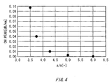
| Fiber ID No. | Outer diameter a (µm) of section corresponding to core rod inside optical fiber | Mode field diameter m (µm) at 1385nm in wavelength | a/m | OH peak (dB/km) |
| 1 | 33.7 | 9.6 | 3.51 | 0.097 |
| 2 | 36.0 | 9.6 | 3.75 | 0.040 |
| 3 | 41.2 | 9.6 | 4.29 | 0.010 |
| 4 | 48.0 | 9.6 | 5.00 | 0.002 |
| 5 | 57.6 | 9.6 | 6.00 | 0.000 |
Claims (7)
- A method for manufacturing a glass base material for an optical fiber by forming a core rod having a core section and a portion of a clad, forming an additional clad through depositing glass particles on circumference of said core rod, and performing a sintering and vitrifying process on an obtained porous base material, comprising the step of:forming said core rod in order that a relation 3.75≤a/m≤6 is satisfied, where 'a' denotes an outer diameter of a section corresponding to said core rod, and 'm' denotes a mode field diameter at 1385nm in wavelength with regard to said optical fiber obtained by drawing said glass base material.
- A method for manufacturing a glass base material for an optical fiber as claimed in claim 1, wherein said core rod is manufactured by using one of methods which are VAD, OVD, MCVD and PCVD.
- A method for manufacturing a glass base material for an optical fiber as claimed in claim 1 or 2, wherein average concentration of hydroxyl groups is 1ppb or less in a section of said core rod equivalent to at least 90% of an outer diameter thereof.
- A method for manufacturing a glass base material for an optical fiber as claimed in any one of claims 1, 2 or 3, wherein average concentration of hydroxyl groups is 50ppm or less in a section of said additional clad equivalent to at least 150% of an inner diameter thereof.
- A glass base material for an optical fiber manufactured by said method as claimed in claim 1.
- An optical fiber obtained by heating and drawing said glass base material as claimed in claim 5.
- An optical fiber as claimed in claim 6, wherein a contributionportion of absorption loss causedbyhydroxyl groups is 0.04dB/km or less with regard to a transmission loss spectrum of said optical fiber at about 1385nm in wavelength.
Applications Claiming Priority (2)
| Application Number | Priority Date | Filing Date | Title |
|---|---|---|---|
| JP2003104133 | 2003-04-08 | ||
| JP2003104133A JP2004307280A (en) | 2003-04-08 | 2003-04-08 | Glass preform for optical fiber having reduced absorption by OH group and method for producing the same |
Publications (2)
| Publication Number | Publication Date |
|---|---|
| EP1466873A2 true EP1466873A2 (en) | 2004-10-13 |
| EP1466873A3 EP1466873A3 (en) | 2011-01-05 |
Family
ID=32866723
Family Applications (1)
| Application Number | Title | Priority Date | Filing Date |
|---|---|---|---|
| EP04090123A Withdrawn EP1466873A3 (en) | 2003-04-08 | 2004-03-31 | Glass preform for an optical fiber and manufacturing method thereof |
Country Status (8)
| Country | Link |
|---|---|
| US (1) | US20040200241A1 (en) |
| EP (1) | EP1466873A3 (en) |
| JP (1) | JP2004307280A (en) |
| KR (1) | KR101031562B1 (en) |
| CN (1) | CN1541962B (en) |
| AU (1) | AU2004201476A1 (en) |
| CA (1) | CA2464010A1 (en) |
| TW (1) | TW200427640A (en) |
Families Citing this family (6)
| Publication number | Priority date | Publication date | Assignee | Title |
|---|---|---|---|---|
| JP4160918B2 (en) * | 2004-03-12 | 2008-10-08 | 富士フイルム株式会社 | Optical communication method |
| JP4926164B2 (en) * | 2008-12-26 | 2012-05-09 | 信越化学工業株式会社 | Optical fiber preform manufacturing method and apparatus using high frequency induction thermal plasma torch |
| JP6006185B2 (en) * | 2012-09-24 | 2016-10-12 | 信越化学工業株式会社 | Method for producing porous glass deposit for optical fiber |
| JP6402466B2 (en) * | 2014-03-31 | 2018-10-10 | 住友電気工業株式会社 | Multi-core optical fiber manufacturing method |
| US9618692B2 (en) * | 2014-07-10 | 2017-04-11 | Corning Incorporated | High chlorine content low attenuation optical fiber |
| JP7757664B2 (en) | 2021-08-31 | 2025-10-22 | 住友電気工業株式会社 | optical fiber |
Family Cites Families (28)
| Publication number | Priority date | Publication date | Assignee | Title |
|---|---|---|---|---|
| US5888587A (en) * | 1992-07-07 | 1999-03-30 | Alcatel N.V. | Method of manufacturing silica powder and use of such powder in making an optical fiber preform |
| US5373576A (en) * | 1993-05-04 | 1994-12-13 | Polaroid Corporation | High power optical fiber |
| DE69420818T2 (en) * | 1993-11-29 | 2000-05-25 | At & T Corp., New York | Process for making optical fiber preforms |
| US5397372A (en) * | 1993-11-30 | 1995-03-14 | At&T Corp. | MCVD method of making a low OH fiber preform with a hydrogen-free heat source |
| BR9506216A (en) | 1994-04-25 | 1997-09-30 | Furukawa Electric Co Ltd | Fiber optic preform and fiber optic production process |
| JP2919300B2 (en) * | 1994-04-25 | 1999-07-12 | 古河電気工業株式会社 | Dispersion shifted single mode optical fiber |
| KR0153835B1 (en) * | 1995-11-07 | 1998-11-16 | 김광호 | Process for preparation of optical glass fiber |
| JP3731243B2 (en) * | 1996-04-01 | 2006-01-05 | 住友電気工業株式会社 | Single mode optical fiber and manufacturing method thereof |
| JP3675579B2 (en) * | 1996-08-08 | 2005-07-27 | 住友電気工業株式会社 | Manufacturing method of optical fiber preform |
| US6131415A (en) * | 1997-06-20 | 2000-10-17 | Lucent Technologies Inc. | Method of making a fiber having low loss at 1385 nm by cladding a VAD preform with a D/d<7.5 |
| CA2335879C (en) * | 1998-06-25 | 2004-11-23 | Samsung Electronics Co., Ltd. | Optical fiber preform having oh barrier and manufacturing method thereof |
| US6334338B1 (en) * | 1998-07-02 | 2002-01-01 | Lucent Technologies Inc. | Sol gel process of making a fiber preform with removal of oxide particles |
| US6105396A (en) * | 1998-07-14 | 2000-08-22 | Lucent Technologies Inc. | Method of making a large MCVD single mode fiber preform by varying internal pressure to control preform straightness |
| JP3819614B2 (en) | 1998-10-16 | 2006-09-13 | 信越石英株式会社 | Method for producing quartz glass preform for optical fiber |
| JP4455740B2 (en) * | 2000-08-02 | 2010-04-21 | 信越化学工業株式会社 | Method for manufacturing preform for optical fiber |
| JP2002187733A (en) * | 2000-12-14 | 2002-07-05 | Furukawa Electric Co Ltd:The | Method for manufacturing optical fiber preform and method for manufacturing optical fiber |
| US6904772B2 (en) * | 2000-12-22 | 2005-06-14 | Corning Incorporated | Method of making a glass preform for low water peak optical fiber |
| JP3758981B2 (en) * | 2001-03-01 | 2006-03-22 | 古河電気工業株式会社 | Optical fiber |
| JP2003114347A (en) * | 2001-07-30 | 2003-04-18 | Furukawa Electric Co Ltd:The | Single mode optical fiber, manufacturing method and manufacturing apparatus |
| KR100420175B1 (en) | 2001-09-08 | 2004-03-02 | 엘지전선 주식회사 | Optical fiber preform and manufacturing method thereof |
| JP2003279780A (en) * | 2002-01-15 | 2003-10-02 | Sumitomo Electric Ind Ltd | Optical fiber, optical fiber tape, optical cable and optical connector with optical fiber |
| EP1333299B1 (en) * | 2002-02-05 | 2010-06-09 | Fujikura Ltd. | Optical fiber and slanted optical fiber grating |
| KR100427446B1 (en) * | 2002-05-13 | 2004-04-17 | 엘지전선 주식회사 | Optical fiber for optical amplifier and production method of the same |
| JP4093553B2 (en) * | 2002-08-07 | 2008-06-04 | 信越化学工業株式会社 | Optical fiber preform, manufacturing method thereof, and optical fiber obtained by drawing the same |
| KR100508707B1 (en) * | 2002-08-12 | 2005-08-17 | 엘에스전선 주식회사 | a manufacturing method and a manufacturing device by Outside Vapor Deposition |
| US20040118164A1 (en) * | 2002-12-19 | 2004-06-24 | Boek Heather D. | Method for heat treating a glass article |
| JP4016913B2 (en) * | 2003-08-28 | 2007-12-05 | 住友電気工業株式会社 | Optical module and optical module assembling method |
| US7248767B2 (en) * | 2004-03-13 | 2007-07-24 | Optiworks, Inc. | Multimode optical fiber coupler and fabrication method |
-
2003
- 2003-04-08 JP JP2003104133A patent/JP2004307280A/en active Pending
-
2004
- 2004-03-15 TW TW093106799A patent/TW200427640A/en unknown
- 2004-03-31 EP EP04090123A patent/EP1466873A3/en not_active Withdrawn
- 2004-04-05 CN CN2004100310042A patent/CN1541962B/en not_active Expired - Fee Related
- 2004-04-06 KR KR1020040023471A patent/KR101031562B1/en not_active Expired - Fee Related
- 2004-04-07 AU AU2004201476A patent/AU2004201476A1/en not_active Abandoned
- 2004-04-08 CA CA002464010A patent/CA2464010A1/en not_active Abandoned
- 2004-04-08 US US10/819,955 patent/US20040200241A1/en not_active Abandoned
Also Published As
| Publication number | Publication date |
|---|---|
| TW200427640A (en) | 2004-12-16 |
| CA2464010A1 (en) | 2004-10-08 |
| AU2004201476A1 (en) | 2004-10-28 |
| KR101031562B1 (en) | 2011-04-27 |
| CN1541962B (en) | 2012-01-18 |
| KR20040087895A (en) | 2004-10-15 |
| JP2004307280A (en) | 2004-11-04 |
| EP1466873A3 (en) | 2011-01-05 |
| US20040200241A1 (en) | 2004-10-14 |
| CN1541962A (en) | 2004-11-03 |
Similar Documents
| Publication | Publication Date | Title |
|---|---|---|
| US8295668B2 (en) | Low loss optical fiber designs and methods for their manufacture | |
| EP0887670B1 (en) | Method of fabricating an optical fibre having low loss at 1385 nm | |
| US4339174A (en) | High bandwidth optical waveguide | |
| US4385802A (en) | Long wavelength, low-loss optical waveguide | |
| US5995695A (en) | Dispersion compensating optical fiber | |
| US20020136515A1 (en) | Substrate tube and process for producing a preform for an optical fiber | |
| CN100374886C (en) | Single mode optical fibre and producing method thereof | |
| US20080285927A1 (en) | Single Mode Optical Fiber Having Reduced Macrobending and Attenuation Loss and Method for Manufacturing the Same | |
| KR20040014239A (en) | Optical fiber preform, method for manufacturing thereof, and optical fiber obtained by drawing thereof | |
| CN102165345A (en) | Optical fiber and method for manufacturing the same | |
| US20040200241A1 (en) | Glass base material for optical fiber and manufacturing method thereof where absorption by hydroxyl groups is reduced | |
| KR102944739B1 (en) | Optical fiber | |
| US8567217B2 (en) | Optical fiber preform and manufacturing method therefor | |
| HK1067619A (en) | Glass preform for an optical fiber and manufacturing method thereof | |
| US7391946B2 (en) | Low attenuation optical fiber and its producing method in MCVD | |
| US6865327B2 (en) | Method of making optical fiber with reduced E-band and L-band loss peaks | |
| JP2005181414A (en) | Optical fiber manufacturing method | |
| EP4579292A1 (en) | Single mode optical fiber | |
| HK1071882A (en) | Glass preform for optical fiber in which absorption due to hydroxide group is reduced and a method of manufacturing the same |
Legal Events
| Date | Code | Title | Description |
|---|---|---|---|
| PUAI | Public reference made under article 153(3) epc to a published international application that has entered the european phase |
Free format text: ORIGINAL CODE: 0009012 |
|
| AK | Designated contracting states |
Kind code of ref document: A2 Designated state(s): AT BE BG CH CY CZ DE DK EE ES FI FR GB GR HU IE IT LI LU MC NL PL PT RO SE SI SK TR |
|
| AX | Request for extension of the european patent |
Extension state: AL HR LT LV MK |
|
| REG | Reference to a national code |
Ref country code: HK Ref legal event code: DE Ref document number: 1067619 Country of ref document: HK |
|
| PUAL | Search report despatched |
Free format text: ORIGINAL CODE: 0009013 |
|
| AK | Designated contracting states |
Kind code of ref document: A3 Designated state(s): AT BE BG CH CY CZ DE DK EE ES FI FR GB GR HU IE IT LI LU MC NL PL PT RO SE SI SK TR |
|
| AX | Request for extension of the european patent |
Extension state: AL LT LV MK |
|
| STAA | Information on the status of an ep patent application or granted ep patent |
Free format text: STATUS: THE APPLICATION HAS BEEN WITHDRAWN |
|
| 18W | Application withdrawn |
Effective date: 20110118 |
|
| REG | Reference to a national code |
Ref country code: HK Ref legal event code: WD Ref document number: 1067619 Country of ref document: HK |