EP1466389B1 - Patch plug design and methods for use thereof - Google Patents
Patch plug design and methods for use thereof Download PDFInfo
- Publication number
- EP1466389B1 EP1466389B1 EP03702142A EP03702142A EP1466389B1 EP 1466389 B1 EP1466389 B1 EP 1466389B1 EP 03702142 A EP03702142 A EP 03702142A EP 03702142 A EP03702142 A EP 03702142A EP 1466389 B1 EP1466389 B1 EP 1466389B1
- Authority
- EP
- European Patent Office
- Prior art keywords
- patch plug
- terminals
- housing
- hinge member
- cover portion
- Prior art date
- Legal status (The legal status is an assumption and is not a legal conclusion. Google has not performed a legal analysis and makes no representation as to the accuracy of the status listed.)
- Expired - Lifetime
Links
- 238000000034 method Methods 0.000 title claims description 14
- 125000006850 spacer group Chemical group 0.000 claims description 12
- 238000009413 insulation Methods 0.000 claims description 7
- 238000006073 displacement reaction Methods 0.000 claims description 6
- 230000008878 coupling Effects 0.000 claims description 3
- 238000010168 coupling process Methods 0.000 claims description 3
- 238000005859 coupling reaction Methods 0.000 claims description 3
- 230000001939 inductive effect Effects 0.000 claims description 2
- 230000000087 stabilizing effect Effects 0.000 claims description 2
- 238000009434 installation Methods 0.000 abstract description 9
- CUGLICQCTXWQNF-UHFFFAOYSA-N 1,2-dichloro-3-(2,6-dichlorophenyl)benzene Chemical compound ClC1=CC=CC(C=2C(=CC=CC=2Cl)Cl)=C1Cl CUGLICQCTXWQNF-UHFFFAOYSA-N 0.000 description 9
- 230000000295 complement effect Effects 0.000 description 4
- 238000005516 engineering process Methods 0.000 description 3
- 230000013011 mating Effects 0.000 description 3
- 230000009977 dual effect Effects 0.000 description 2
- 238000012369 In process control Methods 0.000 description 1
- 230000015556 catabolic process Effects 0.000 description 1
- 239000004020 conductor Substances 0.000 description 1
- 238000002788 crimping Methods 0.000 description 1
- 210000004544 dc2 Anatomy 0.000 description 1
- 238000006731 degradation reaction Methods 0.000 description 1
- 230000003116 impacting effect Effects 0.000 description 1
- 238000004190 ion pair chromatography Methods 0.000 description 1
- 238000012986 modification Methods 0.000 description 1
- 230000004048 modification Effects 0.000 description 1
- 230000006641 stabilisation Effects 0.000 description 1
- 238000011105 stabilization Methods 0.000 description 1
Images





Classifications
-
- H—ELECTRICITY
- H01—ELECTRIC ELEMENTS
- H01R—ELECTRICALLY-CONDUCTIVE CONNECTIONS; STRUCTURAL ASSOCIATIONS OF A PLURALITY OF MUTUALLY-INSULATED ELECTRICAL CONNECTING ELEMENTS; COUPLING DEVICES; CURRENT COLLECTORS
- H01R13/00—Details of coupling devices of the kinds covered by groups H01R12/70 or H01R24/00 - H01R33/00
- H01R13/46—Bases; Cases
- H01R13/502—Bases; Cases composed of different pieces
- H01R13/506—Bases; Cases composed of different pieces assembled by snap action of the parts
-
- H—ELECTRICITY
- H01—ELECTRIC ELEMENTS
- H01R—ELECTRICALLY-CONDUCTIVE CONNECTIONS; STRUCTURAL ASSOCIATIONS OF A PLURALITY OF MUTUALLY-INSULATED ELECTRICAL CONNECTING ELEMENTS; COUPLING DEVICES; CURRENT COLLECTORS
- H01R13/00—Details of coupling devices of the kinds covered by groups H01R12/70 or H01R24/00 - H01R33/00
- H01R13/646—Details of coupling devices of the kinds covered by groups H01R12/70 or H01R24/00 - H01R33/00 specially adapted for high-frequency, e.g. structures providing an impedance match or phase match
- H01R13/6473—Impedance matching
- H01R13/6477—Impedance matching by variation of dielectric properties
-
- H—ELECTRICITY
- H01—ELECTRIC ELEMENTS
- H01R—ELECTRICALLY-CONDUCTIVE CONNECTIONS; STRUCTURAL ASSOCIATIONS OF A PLURALITY OF MUTUALLY-INSULATED ELECTRICAL CONNECTING ELEMENTS; COUPLING DEVICES; CURRENT COLLECTORS
- H01R13/00—Details of coupling devices of the kinds covered by groups H01R12/70 or H01R24/00 - H01R33/00
- H01R13/66—Structural association with built-in electrical component
- H01R13/665—Structural association with built-in electrical component with built-in electronic circuit
- H01R13/6658—Structural association with built-in electrical component with built-in electronic circuit on printed circuit board
-
- H—ELECTRICITY
- H04—ELECTRIC COMMUNICATION TECHNIQUE
- H04Q—SELECTING
- H04Q1/00—Details of selecting apparatus or arrangements
- H04Q1/02—Constructional details
- H04Q1/021—Constructional details using pivoting mechanisms for accessing the interior of the apparatus
-
- H—ELECTRICITY
- H04—ELECTRIC COMMUNICATION TECHNIQUE
- H04Q—SELECTING
- H04Q1/00—Details of selecting apparatus or arrangements
- H04Q1/02—Constructional details
- H04Q1/13—Patch panels for monitoring, interconnecting or testing circuits, e.g. patch bay, patch field or jack field; Patching modules
-
- H—ELECTRICITY
- H01—ELECTRIC ELEMENTS
- H01R—ELECTRICALLY-CONDUCTIVE CONNECTIONS; STRUCTURAL ASSOCIATIONS OF A PLURALITY OF MUTUALLY-INSULATED ELECTRICAL CONNECTING ELEMENTS; COUPLING DEVICES; CURRENT COLLECTORS
- H01R13/00—Details of coupling devices of the kinds covered by groups H01R12/70 or H01R24/00 - H01R33/00
- H01R13/646—Details of coupling devices of the kinds covered by groups H01R12/70 or H01R24/00 - H01R33/00 specially adapted for high-frequency, e.g. structures providing an impedance match or phase match
- H01R13/6461—Means for preventing cross-talk
- H01R13/6464—Means for preventing cross-talk by adding capacitive elements
- H01R13/6466—Means for preventing cross-talk by adding capacitive elements on substrates, e.g. printed circuit boards [PCB]
-
- H—ELECTRICITY
- H01—ELECTRIC ELEMENTS
- H01R—ELECTRICALLY-CONDUCTIVE CONNECTIONS; STRUCTURAL ASSOCIATIONS OF A PLURALITY OF MUTUALLY-INSULATED ELECTRICAL CONNECTING ELEMENTS; COUPLING DEVICES; CURRENT COLLECTORS
- H01R4/00—Electrically-conductive connections between two or more conductive members in direct contact, i.e. touching one another; Means for effecting or maintaining such contact; Electrically-conductive connections having two or more spaced connecting locations for conductors and using contact members penetrating insulation
- H01R4/24—Connections using contact members penetrating or cutting insulation or cable strands
-
- H—ELECTRICITY
- H01—ELECTRIC ELEMENTS
- H01R—ELECTRICALLY-CONDUCTIVE CONNECTIONS; STRUCTURAL ASSOCIATIONS OF A PLURALITY OF MUTUALLY-INSULATED ELECTRICAL CONNECTING ELEMENTS; COUPLING DEVICES; CURRENT COLLECTORS
- H01R4/00—Electrically-conductive connections between two or more conductive members in direct contact, i.e. touching one another; Means for effecting or maintaining such contact; Electrically-conductive connections having two or more spaced connecting locations for conductors and using contact members penetrating insulation
- H01R4/24—Connections using contact members penetrating or cutting insulation or cable strands
- H01R4/2416—Connections using contact members penetrating or cutting insulation or cable strands the contact members having insulation-cutting edges, e.g. of tuning fork type
- H01R4/242—Connections using contact members penetrating or cutting insulation or cable strands the contact members having insulation-cutting edges, e.g. of tuning fork type the contact members being plates having a single slot
- H01R4/2425—Flat plates, e.g. multi-layered flat plates
- H01R4/2429—Flat plates, e.g. multi-layered flat plates mounted in an insulating base
-
- H—ELECTRICITY
- H01—ELECTRIC ELEMENTS
- H01R—ELECTRICALLY-CONDUCTIVE CONNECTIONS; STRUCTURAL ASSOCIATIONS OF A PLURALITY OF MUTUALLY-INSULATED ELECTRICAL CONNECTING ELEMENTS; COUPLING DEVICES; CURRENT COLLECTORS
- H01R43/00—Apparatus or processes specially adapted for manufacturing, assembling, maintaining, or repairing of line connectors or current collectors or for joining electric conductors
- H01R43/01—Apparatus or processes specially adapted for manufacturing, assembling, maintaining, or repairing of line connectors or current collectors or for joining electric conductors for connecting unstripped conductors to contact members having insulation cutting edges
-
- H—ELECTRICITY
- H04—ELECTRIC COMMUNICATION TECHNIQUE
- H04Q—SELECTING
- H04Q2201/00—Constructional details of selecting arrangements
- H04Q2201/12—Printed circuits
-
- Y—GENERAL TAGGING OF NEW TECHNOLOGICAL DEVELOPMENTS; GENERAL TAGGING OF CROSS-SECTIONAL TECHNOLOGIES SPANNING OVER SEVERAL SECTIONS OF THE IPC; TECHNICAL SUBJECTS COVERED BY FORMER USPC CROSS-REFERENCE ART COLLECTIONS [XRACs] AND DIGESTS
- Y10—TECHNICAL SUBJECTS COVERED BY FORMER USPC
- Y10S—TECHNICAL SUBJECTS COVERED BY FORMER USPC CROSS-REFERENCE ART COLLECTIONS [XRACs] AND DIGESTS
- Y10S493/00—Manufacturing container or tube from paper; or other manufacturing from a sheet or web
- Y10S493/941—Filter
Definitions
- the present disclosure relates to innovative patch plug designs that facilitate, inter alia, easy and effective connector termination in the field.
- Patch plug designs for use with patch cords e.g., conventional cables that include a plurality of twisted pair wires
- Lucent Technologies provides a patch plug/patch cord assembly that is fabricated from top and bottom patch plug housings.
- the top and bottom housings also referred to as “base” and “cover” housings
- base and cover housings include cooperative latching fingers/slots that are employed to establish and maintain the respective housings in fixed alignment alter the wires from the patch cord are properly positioned therebetween.
- each housing is substantially planar in design, and the units available from Lucent Technologies are fabricated in a factory environment.
- the commercially available units according to the Lucent design include patch plugs that are pre-secured to patch cords, such that the patch cords extend from the patch plugs when purchased by potential users thereof.
- EP 1150389 A1 discloses a clamshell connector for an airbag gas generator, having a living hinge across a cover and housing so as to provide for hinged deflection of a cover clamshell component and a housing clamshell component, defining an enclosable clamshell cavity therebetween. Crimping ends of electrical contacts are provided within the clamshell cavity to provide easier access to crimp wires thereto. This document corresponds to the preamble of Claim 1.
- a patch plug design that facilitates enhanced flexibility in implementation and use.
- a patch plug design that provides/facilitates enhanced performance e.g., reduced NEXT and FEXT noises, would be desirable.
- innovative patch plug designs are provided that facilitate, inter alia, easy and effective connector termination in the field.
- Exemplary embodiments of the disclosed patch plugs may be advantageously installed in the field using conventional equipment, e.g., a conventional punch tool.
- the advantageously disclosed patch plug designs effectively address inherent space constraints to facilitate connection between a series of insulation displacement connectors ("IDCs") and a wire, e.g., a twisted pair cable, to form an advantageous patch cord.
- the disclosed patch plug includes a printed circuit board having proprietary features to provide enhanced performance (e.g., to achieve reduced near end crosstalk).
- the present disclosure also relates to advantageous field implementations utilizing the disclosed patch plug designs.
- Preferred patch plugs include hinge members that are living hinges, terminals that are fabricated with associated contact blades, compliant eyes, and IDCs (or IPCs) incorporated into an integral member to contribute to improved performance of such patch plug.
- FIG. 1-12 illustrate aspects of an exemplary patch plug embodiment in accordance with the present disclosure.
- the exemplary patch plug embodiments of the present disclosure are shown without cabling/wiring attached and/or integrated therewith.
- wiring of the exemplary patch plugs as disclosed herein may be accomplished using conventional equipment, e.g., using conventional punch tools in a field environment
- Preferred and exemplary wiring/trace arrangements for enhanced performance according to the present disclosure are also disclosed herein.
- an exemplary patch plug 10 is depicted that includes a cover 12 and a lower housing 14.
- Cover 12 and lower housing 14 define substantially identical geometries so that, when mated, they form a substantially integral patch plug unit as shown in Fig. 1 .
- cover 12 includes a hinge member 16 at an intermediate location, hinge member 16 defining front cover portion 18 and rear cover portion 20.
- hinge member 16 comprises two individual hinge members 16a, 16b that are bounded by apertures through which latching fingers 22a, 22b, 22c protrude.
- hinge member 16 may take the form of a single hinge member, dual hinge members (as shown), or greater numbers of individual hinge members, without departing from the spirit and scope of the present disclosure.
- lower housing 14 of exemplary patch plug 10 also includes a complementary hinge member 22 at an intermediate location thereof, such complementary hinge member 22 defining front housing portion 24 and rear housing portion 26.
- hinge member 16 and complementary hinge member 22 are at substantially identical intermediate locations relative to cover 12 and lower housing 14, respectively.
- pivotal or rotational motion of front cover portion 18 relative to rear cover portion 20, and pivotal or rotational motion of front housing portion 24 relative to rear housing portion 26 takes place around or relative to substantially aligned rotational axes.
- hinge members 16, 22 are living hinges.
- cover 12 and housing 14 are highly advantageous in permitting/facilitating patch plug installations in the field. More particularly, by pivoting/rotating front housing portion 24 and front cover portion 18 to the relative positions shown in Figs. 2 , 3 and 7 , field personnel can easily and efficiently introduce/mount wires from a desired cable into exemplary patch plug 10, e.g., using a conventional punch tool. Field installation is particularly facilitated because punch tool access is facilitated from both sides of towers 28 formed in or extending from housing 14. By facilitating field installation of patch plugs onto cable(s), the present disclosure greatly enhances the flexibility and efficiency associated with a wide range of wiring applications.
- exemplary patch plug 10 is depicted with cover 12 separated from lower housing 14.
- latch members 30, 32, 34 extend downwardly from rear cover portion 20 of cover 12.
- Each latch member 30, 32, 34 includes a latching finger at the exposed end thereof, such latching finger adapted to engage apertures formed in lower housing 14 (see apertures 60a, 60b, 60c in Fig. 8 ) by passing through corresponding slots formed in spacer 36 that is mounted to rear housing portion 24 of housing 12.
- latch members 30, 32, 34 are engaged with the apertures 60a, 60b, 60c formed in housing 14
- the rear cover portion 20 is secured to the corresponding rear housing portion 26 of housing 14.
- front cover portion 18 and front housing portion 24 maintain rotational/pivotal freedom of motion around the substantially aligned rotational axes defined by hinge member 16 and complementary hinge member 22.
- the degree to which front cover portion 18 and front housing portion 24 maintain rotational/pivotal freedom of motion can vary according to the present disclosure. It is contemplated that the degree of rotational/pivotal freedom of motion is such that field personnel are allowed to easily and effectively achieve patch plug/wire installations using conventional punch tooling. Thus, in a preferred embodiment of the present disclosure, rotational/pivotal freedom of motion is such that both front cover portion 18 and front housing portion 24 are able to rotate/pivot at least 90° relative to their respective rotational/pivotal axes. Patch plug designs with greater and/or lesser degrees of rotational/pivotal freedom of motion may be provided according to the present disclosure, so long as advantageous field installations are enabled thereby.
- a further view of exemplary patch plug 10 is provided wherein cover 12 is separated from lower housing 14.
- a cable (not pictured) can be positioned within patch plug 10 by passing through an outer passage formed by cooperative semi-circular cutouts 38 formed in cover 12 and lower housing 14.
- a further set of semi-circular supporting walls 40 are formed within the interior of cover 12 and lower housing 14 to further stabilize and capture a cable (not pictured) positioned therewithin.
- Downwardly extending latching fingers 42a, 42b protrude from cover 12 and are adapted to engage cooperative slots formed in lower housing to secure front cover portion 18 to front housing portion 24.
- FIG. 10 an exemplary, substantially L-shaped terminal 44 according to the present disclosure is depicted.
- Terminal 44 features a contact blade feature 48 on leg portion 50 for mating with a corresponding connector, e.g., an IDC feature on a 110C-4 clip, as is known in the art.
- Leg portion 50 is preferably integrally formed with extension 52, and includes a transverse extension 55 that defines abutment shoulders 54a, 54b.
- Compliant eye 56 and a terminating insulation displacement connector (IDC) feature 58 for mating with individual wires are also provided. Due to transverse extension 55, compliant eye 56 and IDC feature 58 are rotated approximately 90° relative to the orientation of leg portion 50 and extension 52.
- IDC insulation displacement connector
- FIG. 11 an alternative, substantially L-shaped terminal 44' is depicted, such alternative terminal 44' including a contact blade feature 48' on leg portion 50' for mating with a corresponding connector.
- Leg portion 50' is preferably integrally formed with extension 52' that defines abutment shoulders 54a', 54b', a compliant eye 56', and a terminating insulating piercing connector (IPC) feature 58'.
- IPC terminating insulating piercing connector
- terminal 44' lacks a transverse aspect (e.g., transverse extension 55) and therefore compliant eye 56' and IPC feature 58' of IDC 44' are not rotated relative to the orientation of leg portion 50' and extension 52'.
- Terminals 44, 44' are fabricated from an appropriate conductive material, as is known in the art. By fabricating terminals 44, 44' such that the contact blade, compliant eye and IDC (or IPC) are incorporated into a single, integral component, potential performance degradations are avoided, and optimal performance may be preferably achieved according to preferred embodiments of the present disclosure.
- terminals 44, 44' are positioned in alternating pairs, such that a first pair of terminals 44, 44' are positioned such that leg portions 50, 50' are downwardly positioned, i.e., directed into lower housing 14; the next pair of terminals 44, 44' are positioned with leg portions upwardly directed, i.e., away from lower housing 14; etc.
- return loss performance is improved.
- additional performance characteristics are improved, e.g., reduced crosstalk. Accordingly, overall patch plug performance may be improved in key respects according to preferred embodiments of the present disclosure.
- PCB 46 includes pairs of spaced openings 62 that are adapted to accommodate partial passage of terminal pair extensions 52 therethrough. Abutment shoulders 54a, 54b typically engage PCB 46 to position terminals 44 relative thereto, at which point compliant eyes 54 are typically positioned within PCB 46 and make reliable electrical connection therewith.
- IDC features 58 extend from the opposite side of PCB 46 for electrical connection with wires (not pictured) positioned within exemplary patch plug 10.
- lower housing 14 includes a plurality of spaced, upwardly protruding studs 64 that cooperate with corresponding apertures formed in spacer 36 to position spacer 36 relative to lower housing 14. Similar downwardly protruding studs (not pictured) extend from cover 12 and engage corresponding apertures formed in spacer 36 for further stabilization thereof.
- Spacer 36 defines a plurality of spaced channels 37 within which terminals 44, 44' are positioned to further stabilize and secure terminals 44 relative to exemplary patch plug 10.
- channels 37 are provided in alternating pairs, such that a first set of adjacent pair of channels 37 on an upper portion of spacer 36 are elongated, so as to cooperate with extensions 52 of terminals 44, whereas the next pair of channels 37 in the upper portion of spacer 36 are relatively short, and are intended for cooperation with leg portions 50 of terminals 44.
- spacer 36 and channels 37 are preferably fabricated so as to cooperate with the alternating terminal pair scheme described herein.
- trace layouts or patterns associated with exemplary PCB 46 advantageously provide reduced crosstalk (e.g., NEXT and FEXT) noises in patch plugs according to the present disclosure.
- PCB 46 thus exhibits advantageous balance coupling to reduce noise and re-balance the signal without negatively impacting the impedance characteristics of the wire pairs in a simple and low cost manner.
- Electrical noise is reduced by the positional relationship of signals during passage through the PCB, which advantageously compensates for pair to pair NEXT, FEXT and impedance.
- the current-carrying signal does not pass through the PCB positioned within the patch plug.
- Exemplary trace layouts or patterns according to the present disclosure are apparent from the schematic illustrations of Fig. 12 .
- Alternative trace layouts and/or patterns are contemplated and may be used to achieve the desired results disclosed herein.
- the traces in PCB 46 re-balance the wire pairs/terminals by inducing both negative and positive coupling to the adjacent pair wires/terminals.
- FIG. 7 an important, unique and advantageous aspect of exemplary patch plug designs of the present disclosure is further illustrated.
- the contents of front cover portion 18 and front housing portion 24 are fully visible and accessible when front cover portion 18 and front housing portion 24 are rotated/pivoted relative to their respective hinge members.
- towers 28 extend upwardly from rear housing portion 26 and are fully visible and accessible.
- the IDC features 58 (or IPC features 58') are positioned in channels 29 formed between towers 28 and are fully accessible for electrical connection with wires (not pictured) that may be easily and efficiently positioned in contact therewith, e.g., using a conventional punch tool.
- the present disclosure provides advantageous patch plug designs, and method for use thereof, that facilitate field installations using conventional instruments/equipment. Moreover, a system, device and method for reducing crosstalk noise without requiring new equipment or expensive re-wiring is provided. Crosstalk noise may be significantly reduced or even eliminated according to preferred embodiments of the present disclosure by a combination of appropriately placed positive feedback signal reactance circuitry and by utilizing a noise balancing dual reactance dielectric insert.
Landscapes
- Engineering & Computer Science (AREA)
- Microelectronics & Electronic Packaging (AREA)
- Computer Networks & Wireless Communication (AREA)
- Details Of Connecting Devices For Male And Female Coupling (AREA)
- Manufacturing Of Electrical Connectors (AREA)
- Coupling Device And Connection With Printed Circuit (AREA)
- Connector Housings Or Holding Contact Members (AREA)
- Adornments (AREA)
Abstract
Description
- The present application claims the benefit of a commonly assigned provisional parent application entitled "Patch Plug Design and Methods for Use Thereof," which was filed on January 18, 2002, and assigned Serial No.
601349,911 - The present disclosure relates to innovative patch plug designs that facilitate, inter alia, easy and effective connector termination in the field.
- Patch plug designs for use with patch cords, e.g., conventional cables that include a plurality of twisted pair wires, are known. For example, Lucent Technologies (Morristown, NJ) provides a patch plug/patch cord assembly that is fabricated from top and bottom patch plug housings. The top and bottom housings (also referred to as "base" and "cover" housings) include cooperative latching fingers/slots that are employed to establish and maintain the respective housings in fixed alignment alter the wires from the patch cord are properly positioned therebetween. Of note, each housing is substantially planar in design, and the units available from Lucent Technologies are fabricated in a factory environment. Thus, the commercially available units according to the Lucent design include patch plugs that are pre-secured to patch cords, such that the patch cords extend from the patch plugs when purchased by potential users thereof.
-
EP 1150389 A1 discloses a clamshell connector for an airbag gas generator, having a living hinge across a cover and housing so as to provide for hinged deflection of a cover clamshell component and a housing clamshell component, defining an enclosable clamshell cavity therebetween. Crimping ends of electrical contacts are provided within the clamshell cavity to provide easier access to crimp wires thereto. This document corresponds to the preamble of Claim 1. - In view of the ever-increasing breadth and complexity of wiring applications, it would be highly desirable to provide a patch plug design that facilitates enhanced flexibility in implementation and use. In particular, it would be advantageous to provide a patch plug design that would facilitate easy and effective field wiring thereof. Additionally, a patch plug design that provides/facilitates enhanced performance, e.g., reduced NEXT and FEXT noises, would be desirable.
- These and other objectives are achieved, either individually or collectively, through the advantageous patch plug designs and methods disclosed herein.
- According to the present disclosure, innovative patch plug designs are provided that facilitate, inter alia, easy and effective connector termination in the field. Exemplary embodiments of the disclosed patch plugs may be advantageously installed in the field using conventional equipment, e.g., a conventional punch tool.
- The advantageously disclosed patch plug designs effectively address inherent space constraints to facilitate connection between a series of insulation displacement connectors ("IDCs") and a wire, e.g., a twisted pair cable, to form an advantageous patch cord. In preferred embodiments of the present disclosure, the disclosed patch plug includes a printed circuit board having proprietary features to provide enhanced performance (e.g., to achieve reduced near end crosstalk). The present disclosure also relates to advantageous field implementations utilizing the disclosed patch plug designs.
- The patch plug according to one aspect of the invention is characterized in that:
- (a) a cover (12) includes a first hinge member (16) defining a front cover position (18) and a rear cover portion (20);
- (b) a housing (14) that includes a second hinge member (22) defining a front housing portion (24) and a rear housing portion (26); and
- (c) a plurality of terminals (44) mounted with respect to said housing;
characterized in that:- a plurality of spaced towers (28) are formed in said housing (14) and extend from said rear housing portion (26);
- each of said plurality of terminals (44) includes an IDC (58) at an end thereof;
- said IDCs (58) are positioned between said spaced towers (28); and
- each of said plurality of terminals (44) is mounted with respect to said housing (14) such that said IDC (58) is exposed for electrical connection when said front cover portion (18) is rotated relative to said rear cover portion (20) around said first hinge member (16), and when said front housing portion (24) is rotated relative to said rear housing portion (26) around said second hinge member (22).A method of wiring a patch plug according to another aspect of this invention is characterized by:
- rotating said front cover portion relative to said rear cover portion around said first hinge member;
- rotating said front housing portion relative to said rear housing portion around said second hinge member;
- accessing a plurality of insulation displacement connectors (58) that extend from said rear cover portion and said rear housing portion;
- connecting at least one wire with respect to at least one of said plurality of insulation displacement connectors; and
- rotating said front cover portion and said front housing portion into engagement with said plurality of insulation displacement connectors positioned therewith.
- According to a further feature, rotational/pivotal motion of the cover and the housing relative to the first and second hinge members facilitates establishing electrical connection between wires and the IDCs. Preferred patch plugs according to the present disclosure include hinge members that are living hinges, terminals that are fabricated with associated contact blades, compliant eyes, and IDCs (or IPCs) incorporated into an integral member to contribute to improved performance of such patch plug.
- These and other unique features of the disclosed systems, devices and methods of the present disclosure will become more readily apparent from the drawings taken in conjunction with the detailed description of preferred and exemplary embodiments provided herein.
- So that those having ordinary skill in the art to which the subject disclosure appertains will more readily understand how to construct and employ the subject disclosure, reference may be had to the drawings wherein:
-
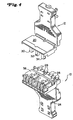
Figure 1 is a perspective view of an exemplary patch plug device in accordance with the present disclosure. -
Figure 2 is a perspective view of the exemplary patch plug device ofFig. 1 , wherein portions of the patch plug housings have been reoriented according to preferred aspects of the present disclosure. -
Figure 3 is a further perspective view of the exemplary patch plug device ofFig. 1 , wherein portions of the patch plug housings have been reoriented according to preferred aspects of the present disclosure. -
Figure 4 is a perspective view of the exemplary patch plug device ofFig. 1 , wherein portions of the patch plug housings have been reoriented and, as compared to the prior view ofFig. 2 , the respective housings have been separated. -
Figure 5 is an additional perspective view of the exemplary patch plug device ofFig. 1 , wherein the respective housings have been separated. -
Figure 6 is a further perspective view of the exemplary patch plug device ofFig. 1 , similar to the prior view ofFig. 5 , wherein the respective housings have been separated and the exemplary spacer removed. -
Figure 7 is a top view of an exemplary housing and cover in the orientation ofFig. 3 . -
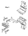
Figure 8 is an exploded perspective view of an exemplary patch plug device according to the present disclosure. -
Figure 9 is a further exploded perspective view of an exemplary patch plug device according to the present disclosure, wherein portions of the patch plug housings have been reoriented according to preferred aspects of the present disclosure. -
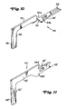
Figure 10 is a perspective view of an exemplary terminal with IDCs according to the present disclosure. -
Figure 11 is a perspective view of an exemplary and alternative terminal with insulation piercing connector ("IPC") feature according to the present disclosure. -
Figure 12 is a plan view of an exemplary trace layout for a printed circuit board for use according to the present disclosure. - These and other features of the disclosed patch plug device and methods for use thereof will become more readily apparent to those having ordinary skill in the art from the following detailed description of preferred and exemplary embodiments.
- Referring now to the drawings,
Figures 1-12 illustrate aspects of an exemplary patch plug embodiment in accordance with the present disclosure. In each of the referenced figures, the exemplary patch plug embodiments of the present disclosure are shown without cabling/wiring attached and/or integrated therewith. As will be readily apparent to persons skilled in the art, wiring of the exemplary patch plugs as disclosed herein may be accomplished using conventional equipment, e.g., using conventional punch tools in a field environment Preferred and exemplary wiring/trace arrangements for enhanced performance according to the present disclosure are also disclosed herein. - With particular reference to
Figs. 1 and2 , anexemplary patch plug 10 is depicted that includes acover 12 and alower housing 14.Cover 12 andlower housing 14 define substantially identical geometries so that, when mated, they form a substantially integral patch plug unit as shown inFig. 1 . As described in greater detail hereinbelow,cover 12 includes ahinge member 16 at an intermediate location,hinge member 16 definingfront cover portion 18 andrear cover portion 20. As shown,hinge member 16 comprises twoindividual hinge members fingers Fig. 6 , latchingfingers lower housing 14 and assist in securinglower housing 14 to cover 12. As will be apparent to persons skilled in the art,hinge member 16 may take the form of a single hinge member, dual hinge members (as shown), or greater numbers of individual hinge members, without departing from the spirit and scope of the present disclosure. - As shown in
Figs. 2-4 ,lower housing 14 of exemplary patch plug 10 also includes acomplementary hinge member 22 at an intermediate location thereof, suchcomplementary hinge member 22 definingfront housing portion 24 andrear housing portion 26. In preferred embodiments of the present disclosure,hinge member 16 andcomplementary hinge member 22 are at substantially identical intermediate locations relative to cover 12 andlower housing 14, respectively. Thus, pivotal or rotational motion offront cover portion 18 relative torear cover portion 20, and pivotal or rotational motion offront housing portion 24 relative torear housing portion 26, takes place around or relative to substantially aligned rotational axes. According to preferred embodiments of the present disclosure,hinge members - The pivotal/rotational functionalities associated with
cover 12 andhousing 14 according to the present disclosure are highly advantageous in permitting/facilitating patch plug installations in the field. More particularly, by pivoting/rotatingfront housing portion 24 andfront cover portion 18 to the relative positions shown inFigs. 2 ,3 and7 , field personnel can easily and efficiently introduce/mount wires from a desired cable intoexemplary patch plug 10, e.g., using a conventional punch tool. Field installation is particularly facilitated because punch tool access is facilitated from both sides oftowers 28 formed in or extending fromhousing 14. By facilitating field installation of patch plugs onto cable(s), the present disclosure greatly enhances the flexibility and efficiency associated with a wide range of wiring applications. - Turning to
Fig. 4 ,exemplary patch plug 10 is depicted withcover 12 separated fromlower housing 14. As shown therein,latch members rear cover portion 20 ofcover 12. Eachlatch member apertures Fig. 8 ) by passing through corresponding slots formed inspacer 36 that is mounted torear housing portion 24 ofhousing 12. Thus, whenlatch members apertures housing 14, therear cover portion 20 is secured to the correspondingrear housing portion 26 ofhousing 14. However,front cover portion 18 andfront housing portion 24 maintain rotational/pivotal freedom of motion around the substantially aligned rotational axes defined byhinge member 16 andcomplementary hinge member 22. - The degree to which
front cover portion 18 andfront housing portion 24 maintain rotational/pivotal freedom of motion can vary according to the present disclosure. It is contemplated that the degree of rotational/pivotal freedom of motion is such that field personnel are allowed to easily and effectively achieve patch plug/wire installations using conventional punch tooling. Thus, in a preferred embodiment of the present disclosure, rotational/pivotal freedom of motion is such that bothfront cover portion 18 andfront housing portion 24 are able to rotate/pivot at least 90° relative to their respective rotational/pivotal axes. Patch plug designs with greater and/or lesser degrees of rotational/pivotal freedom of motion may be provided according to the present disclosure, so long as advantageous field installations are enabled thereby. - With reference to
Fig. 5 , a further view ofexemplary patch plug 10 is provided whereincover 12 is separated fromlower housing 14. As is apparent from the perspective view ofFig. 5 , a cable (not pictured) can be positioned within patch plug 10 by passing through an outer passage formed by cooperativesemi-circular cutouts 38 formed incover 12 andlower housing 14. A further set of semi-circular supportingwalls 40 are formed within the interior ofcover 12 andlower housing 14 to further stabilize and capture a cable (not pictured) positioned therewithin. Downwardly extending latchingfingers cover 12 and are adapted to engage cooperative slots formed in lower housing to securefront cover portion 18 tofront housing portion 24. - With reference to
Figs. 5 and6 , the manner in which spacer 36 cooperates with a plurality ofterminals 44 andlower housing 14 according to an exemplary embodiment of the present disclosure is depicted. As shown therein,spacer 36 assists in stabilizingterminals 44 as they extend through substantially rectangular printed circuit board (PCB) 46. As shown inFig. 10 , an exemplary, substantially L-shapedterminal 44 according to the present disclosure is depicted.Terminal 44 features acontact blade feature 48 onleg portion 50 for mating with a corresponding connector, e.g., an IDC feature on a 110C-4 clip, as is known in the art.Leg portion 50 is preferably integrally formed withextension 52, and includes atransverse extension 55 that definesabutment shoulders Compliant eye 56 and a terminating insulation displacement connector (IDC) feature 58 for mating with individual wires are also provided. Due totransverse extension 55,compliant eye 56 and IDC feature 58 are rotated approximately 90° relative to the orientation ofleg portion 50 andextension 52. - With reference to
Fig. 11 , an alternative, substantially L-shaped terminal 44' is depicted, such alternative terminal 44' including acontact blade feature 48' on leg portion 50' for mating with a corresponding connector. Leg portion 50' is preferably integrally formed with extension 52' that definesabutment shoulders 54a', 54b', a compliant eye 56', and a terminating insulating piercing connector (IPC) feature 58'. As compared toterminal 44, terminal 44' lacks a transverse aspect (e.g., transverse extension 55) and therefore compliant eye 56' and IPC feature 58' of IDC 44' are not rotated relative to the orientation of leg portion 50' and extension 52'. -
Terminals 44, 44' are fabricated from an appropriate conductive material, as is known in the art. By fabricatingterminals 44, 44' such that the contact blade, compliant eye and IDC (or IPC) are incorporated into a single, integral component, potential performance degradations are avoided, and optimal performance may be preferably achieved according to preferred embodiments of the present disclosure. - With further reference to
Figs. 5 and6 , according to a preferred embodiment of the present disclosure,terminals 44, 44' are positioned in alternating pairs, such that a first pair ofterminals 44, 44' are positioned such thatleg portions 50, 50' are downwardly positioned, i.e., directed intolower housing 14; the next pair ofterminals 44, 44' are positioned with leg portions upwardly directed, i.e., away fromlower housing 14; etc. Through the implementation of alternating terminal pairs, as described herein, return loss performance is improved. Moreover, through implementation of innovative noise reduction technologies disclosed herein, additional performance characteristics are improved, e.g., reduced crosstalk. Accordingly, overall patch plug performance may be improved in key respects according to preferred embodiments of the present disclosure. - With reference to the exploded views of
Figs. 8 and9 , the cooperation between alternatingterminal pairs 44 andPCB 46 is further illustrated. Thus,PCB 46 includes pairs of spacedopenings 62 that are adapted to accommodate partial passage ofterminal pair extensions 52 therethrough.Abutment shoulders PCB 46 to positionterminals 44 relative thereto, at which point compliant eyes 54 are typically positioned withinPCB 46 and make reliable electrical connection therewith. Through electrical cooperation withPCB 46, the optimal performance of an exemplary patch plug 10 of the present, disclosure may be achieved. IDC features 58 extend from the opposite side ofPCB 46 for electrical connection with wires (not pictured) positioned withinexemplary patch plug 10. - As is further apparent from the exploded views of
Figs. 8 and9 ,lower housing 14 includes a plurality of spaced, upwardly protrudingstuds 64 that cooperate with corresponding apertures formed inspacer 36 to positionspacer 36 relative to lowerhousing 14. Similar downwardly protruding studs (not pictured) extend fromcover 12 and engage corresponding apertures formed inspacer 36 for further stabilization thereof.Spacer 36 defines a plurality of spacedchannels 37 within whichterminals 44, 44' are positioned to further stabilize andsecure terminals 44 relative toexemplary patch plug 10. In a preferred embodiment of the present disclosure,channels 37 are provided in alternating pairs, such that a first set of adjacent pair ofchannels 37 on an upper portion ofspacer 36 are elongated, so as to cooperate withextensions 52 ofterminals 44, whereas the next pair ofchannels 37 in the upper portion ofspacer 36 are relatively short, and are intended for cooperation withleg portions 50 ofterminals 44. Thus,spacer 36 andchannels 37 are preferably fabricated so as to cooperate with the alternating terminal pair scheme described herein. - With reference to
Figs. 6 ,8 ,9 and12 , trace layouts or patterns associated withexemplary PCB 46 advantageously provide reduced crosstalk (e.g., NEXT and FEXT) noises in patch plugs according to the present disclosure.PCB 46 thus exhibits advantageous balance coupling to reduce noise and re-balance the signal without negatively impacting the impedance characteristics of the wire pairs in a simple and low cost manner. Electrical noise is reduced by the positional relationship of signals during passage through the PCB, which advantageously compensates for pair to pair NEXT, FEXT and impedance. According to preferred embodiments of the present disclosure, the current-carrying signal does not pass through the PCB positioned within the patch plug. - Exemplary trace layouts or patterns according to the present disclosure are apparent from the schematic illustrations of
Fig. 12 . Alternative trace layouts and/or patterns are contemplated and may be used to achieve the desired results disclosed herein. In summary, the traces inPCB 46 re-balance the wire pairs/terminals by inducing both negative and positive coupling to the adjacent pair wires/terminals. - Turning to
Fig. 7 , an important, unique and advantageous aspect of exemplary patch plug designs of the present disclosure is further illustrated. As shown inFig. 7 , the contents offront cover portion 18 andfront housing portion 24 are fully visible and accessible whenfront cover portion 18 andfront housing portion 24 are rotated/pivoted relative to their respective hinge members. Based on such rotational/pivotal orientation offront cover portion 18 andfront housing portion 24, towers 28 extend upwardly fromrear housing portion 26 and are fully visible and accessible. Moreover, the IDC features 58 (or IPC features 58') are positioned inchannels 29 formed betweentowers 28 and are fully accessible for electrical connection with wires (not pictured) that may be easily and efficiently positioned in contact therewith, e.g., using a conventional punch tool. - Through the advantageous deployment of
towers 28 withinlower housing 14, e.g., as shown inexemplary patch plug 10, and the rotational/pivotal functionality ofcover 12 andlower housing 14, field installations usingpatch plug 10 and conventional instrumentation, e.g., a conventional punch tool, are readily achievable. Thereafter,front cover portion 18 andfront housing portion 24 may be rotated/pivoted toward each other and latched together, thereby completing the field installation thereof. - Thus, the present disclosure provides advantageous patch plug designs, and method for use thereof, that facilitate field installations using conventional instruments/equipment. Moreover, a system, device and method for reducing crosstalk noise without requiring new equipment or expensive re-wiring is provided. Crosstalk noise may be significantly reduced or even eliminated according to preferred embodiments of the present disclosure by a combination of appropriately placed positive feedback signal reactance circuitry and by utilizing a noise balancing dual reactance dielectric insert.
- Although the exemplary patch plug designs disclosed herein, and the associated methods for use thereof, have been described with respect to preferred embodiments, it should be readily apparent to persons skilled in the art that modifications and changes may be made thereto without departing from the scope of the invention as defined by the appended claims.
Claims (15)
- A patch plug (10), comprising:(a) a cover (12) that includes a first hinge member (16) defining a front cover portion (18) and a rear cover portion (20);(b) a housing (14) that includes a second hinge member (22) defining a front housing portion (24) and a rear housing portion (26),(c) a plurality of terminals (44) mounted with respect to said housing;characterized in that:a plurality of spaced towers (28) are formed in said housing (14) and extend from said rear housing portion (26);each of said plurality of terminals (44) includes an IDC (58) at an end thereof;said IDCs (58) are positioned between said spaced towers (28); andeach of said plurality of terminals (44) is mounted with respect to said housing (14) such that said IDC (58) is exposed for electrical connection when said front cover portion (18) is rotated relative to said rear cover portion (20) around said first hinge member (16), and when said front housing portion (24) is rotated relative to said rear housing portion (26) around said second hinge member (22).
- A patch plug (10) according to claim 1, wherein said first hinge member (16) and said second hinge member (22) are living hinges.
- A patch plug (10) according to claim 1 or 2, further comprising latching structure (30, 32, 34) for latching said cover to said housing.
- A patch plug (10) according to claim 1, 2 or 3, further comprising at least one spacer (36) for stabilizing said plurality of terminals (44) with respect to said housing (14).
- A patch plug (10) according to any one of the preceding claims, wherein each of said plurality of terminals (44) is substantially L-shaped, and wherein said L-shaped terminals are mounted in alternating pairs with respect to said housing(14).
- A patch plug (10) according to any one of claims 1 to 4, wherein each of said plurality of terminals (44) is substantially L-shaped, and further comprising a printed circuit board (46) with spaced apertures (62) for receiving said plurality of terminals therethrough.
- A patch plug (10) according to claim 6, wherein traces associated with said printed circuit board (46) are oriented so as to contribute to reduced crosstalk by inducing both negative and positive coupling to adjacent pair of wires or terminals.
- A patch plug (10) according to any one of the preceding claims, wherein each of said plurality of terminals (44) is integrally fabricated with a contact blade (48), a compliant eye (56') and an IDC (58).
- A patch plug (10) according to any one of the preceding claims, wherein said first hinge member (16) is positioned at a location intermediate said front cover portion (18) and rear cover portion (20), and wherein said second hinge member (22) is positioned at a location intermediate said front housing portion (24) and rear housing portion (26).
- A patch plug (10) according to any of the claims 1 to 8, wherein said front cover portion (18) is adapted to rotate at least 90° relative to said rear cover portion (20) around said first hinge member (16), and said front housing portion (24) is adapted to rotate at least 90° relative to said rear housing portion (26) around said second hinge member (22).
- A method for wiring a patch plug being characterized by(a) providing a patch plug (10) according to any of the preceding claims;(b) rotating said front cover portion relative to said rear cover portion around said first hinge member ;(c) rotating said front housing portion relative to said rear housing portion around said second hinge member; and(d) connecting at least one wire with respect to at least one of said plurality of insulation displacement connectors.
- A method according to claim 11, wherein each of said plurality of terminals (44) includes an IDC (58), and said at least one wire is connected with respect to said IDC.
- A method according to claim 11 or 12, further comprising:(e) rotating said front housing portion (24) and said front cover portion (18) into engagement with each other; and(f) latching said front housing portion and said front cover portion to each other.
- A method according to any one of claims 11, 12 or 13, further comprising utilizing a punch tool to facilitate connection of said at least one wire with respect to said at least one of said plurality of terminals (44).
- A method according to any one of claims 11 to 14, wherein said patch plug (10) assumes a substantially T-shaped orientation when said housing (14) and said cover (12) are rotated.
Applications Claiming Priority (3)
| Application Number | Priority Date | Filing Date | Title |
|---|---|---|---|
| US34991102P | 2002-01-18 | 2002-01-18 | |
| US349911P | 2002-01-18 | ||
| PCT/US2003/001312 WO2003063302A1 (en) | 2002-01-18 | 2003-01-15 | Patch plug design and methods for use thereof |
Publications (2)
| Publication Number | Publication Date |
|---|---|
| EP1466389A1 EP1466389A1 (en) | 2004-10-13 |
| EP1466389B1 true EP1466389B1 (en) | 2008-05-21 |
Family
ID=27613336
Family Applications (1)
| Application Number | Title | Priority Date | Filing Date |
|---|---|---|---|
| EP03702142A Expired - Lifetime EP1466389B1 (en) | 2002-01-18 | 2003-01-15 | Patch plug design and methods for use thereof |
Country Status (7)
| Country | Link |
|---|---|
| US (1) | US6761589B2 (en) |
| EP (1) | EP1466389B1 (en) |
| JP (1) | JP2005516354A (en) |
| CN (1) | CN1326290C (en) |
| AT (1) | ATE396521T1 (en) |
| DE (1) | DE60321128D1 (en) |
| WO (1) | WO2003063302A1 (en) |
Families Citing this family (44)
| Publication number | Priority date | Publication date | Assignee | Title |
|---|---|---|---|---|
| JP2002367714A (en) * | 2001-06-04 | 2002-12-20 | Yazaki Corp | Wire harness and method of manufacturing wire harness |
| DE10312066B4 (en) * | 2003-03-18 | 2005-12-29 | Erco Leuchten Gmbh | Busbar adapter |
| US7249962B2 (en) * | 2003-11-13 | 2007-07-31 | Belden Cdt (Canada) Inc. | Connector assembly |
| US20080014801A1 (en) * | 2003-11-14 | 2008-01-17 | Luc Milette | Wire guide and connector assembly using same |
| DE102004023446B3 (en) * | 2004-05-12 | 2005-12-29 | Fci | Connector and method of its pre-assembly |
| US20050266721A1 (en) * | 2004-05-26 | 2005-12-01 | Milner John J | Electrical connector with strain relief |
| DE102005007066B3 (en) * | 2005-02-16 | 2006-10-05 | Tyco Electronics Amp Gmbh | Miniaturized electrical plug unit with improved crimpability |
| DE102006039799B3 (en) * | 2006-08-24 | 2007-11-22 | Tyco Electronics Amp Gmbh | Electrical plug, has retainer with holder holding conductor units of cable, and housing units and contact units arranged opposite to retainer, where contact units are connected with conductor units when housing units are in closed position |
| US7503799B2 (en) * | 2006-08-28 | 2009-03-17 | Commscope Inc. | Communications plug with reverse cordage and anti-snag configuration |
| US7416434B2 (en) * | 2006-10-05 | 2008-08-26 | Lumination Llc | IDC splice connector |
| AU314729S (en) * | 2007-03-30 | 2007-06-19 | Tyco Electronics Services Gmbh | Patch plug |
| AU314730S (en) * | 2007-03-30 | 2007-06-19 | Tyco Electronics Services Gmbh | Patch plug |
| US7540749B1 (en) * | 2008-02-06 | 2009-06-02 | Tyco Electronics Corporation | Connector assemblies and systems |
| USD611429S1 (en) * | 2009-01-30 | 2010-03-09 | Group Dekko, Inc | Keying configuration for an electrical connector |
| DE102010014294A1 (en) * | 2010-04-08 | 2011-10-13 | Phoenix Contact Gmbh & Co. Kg | Contact field for connectors |
| FR2965115A1 (en) * | 2010-09-17 | 2012-03-23 | Applic Electro Mecaniques Saam Sa D | CONNECTING HOUSING DEVICE FOR RADIALLY HEATED SLABS. |
| US8702444B2 (en) * | 2010-10-18 | 2014-04-22 | Panduit Corp. | Communication plug with improved cable manager |
| WO2014160995A1 (en) * | 2013-03-29 | 2014-10-02 | Molex Incorporated | Connector with tpa |
| DE202014106058U1 (en) * | 2014-12-15 | 2015-01-21 | Erni Production Gmbh & Co. Kg | Connectors |
| USD766183S1 (en) * | 2015-06-15 | 2016-09-13 | Dsm&T Company, Inc. | Low profile male electrical connector |
| US9871316B2 (en) * | 2016-01-21 | 2018-01-16 | Toshiba Memory Corporation | Electronic device |
| JP2017199497A (en) * | 2016-04-26 | 2017-11-02 | ヒロセ電機株式会社 | Power supply connector including terminal contact prevention mechanism, and power supply connector device using the same |
| DE102016117330A1 (en) * | 2016-09-15 | 2018-03-15 | Knorr-Bremse Systeme für Nutzfahrzeuge GmbH | Housing for a control unit and cover for the housing |
| MX395697B (en) * | 2016-09-23 | 2025-03-25 | Hubbell Inc | ELECTRICAL CONNECTOR FOR CABLES CONTAINING BOTH POWER AND CONTROL CONDUCTORS. |
| USD813821S1 (en) | 2016-09-29 | 2018-03-27 | Dsm&T Company, Inc. | Male electrical connector |
| USD813822S1 (en) | 2016-09-29 | 2018-03-27 | Dsm&T Company, Inc. | Female electrical connector |
| CN108199200B (en) * | 2016-12-08 | 2020-05-12 | 泰科电子(上海)有限公司 | Connector |
| USD818964S1 (en) | 2017-03-23 | 2018-05-29 | Dsm&T Company, Inc. | Female electrical connector with locking arms |
| USD824856S1 (en) | 2017-03-23 | 2018-08-07 | Dsm&T Company, Inc. | Straight female electrical connector with locking arm |
| USD816040S1 (en) | 2017-03-23 | 2018-04-24 | Dsm&T Company, Inc. | Male electrical connector with locking tab |
| USD824862S1 (en) | 2017-03-23 | 2018-08-07 | Dsm&T Company, Inc. | Male electrical connector with locking tabs |
| USD816616S1 (en) | 2017-03-23 | 2018-05-01 | Dsm&T Company, Inc. | 90 degree female electrical connector with locking arm |
| USD838247S1 (en) | 2017-05-18 | 2019-01-15 | Dsm&T Company, Inc. | Mating section of electrical connector |
| USD837741S1 (en) | 2017-05-18 | 2019-01-08 | Dsm&T Company, Inc. | Mating section of electrical connector with locking tabs |
| USD896182S1 (en) | 2018-02-24 | 2020-09-15 | Dsm&T Company, Inc. | Female electrical connector with locking arm |
| USD859320S1 (en) | 2018-02-24 | 2019-09-10 | Dsm&T Company, Inc. | Mating section of male electrical connector |
| US11217934B2 (en) * | 2018-06-22 | 2022-01-04 | Intel Corporation | Socket cover |
| US10790608B2 (en) * | 2018-11-13 | 2020-09-29 | Mellanox Technologies, Ltd. | Apparatuses for improved cable-to-board connections |
| USD915292S1 (en) | 2019-01-22 | 2021-04-06 | Dsm&T Company, Inc. | Electrical connector insert |
| USD924158S1 (en) | 2020-02-24 | 2021-07-06 | Dsm&T Company, Inc. | Connector with locking tabs |
| USD929342S1 (en) | 2020-02-24 | 2021-08-31 | Dsm&T Company, Inc. | Connector with locking arms |
| USD998570S1 (en) | 2021-01-19 | 2023-09-12 | Dsm&T Company, Inc. | Triangular electrical connector with flange |
| USD964287S1 (en) | 2021-01-19 | 2022-09-20 | Dsm&T Company, Inc. | Electrical connector with flange |
| US12407126B2 (en) | 2021-12-17 | 2025-09-02 | Hubbell Incorporated | Low profile wire connector |
Family Cites Families (11)
| Publication number | Priority date | Publication date | Assignee | Title |
|---|---|---|---|---|
| US4062616A (en) * | 1976-08-19 | 1977-12-13 | Amp Incorporated | Flat flexible cable connector assembly including insulation piercing contacts |
| US4195898A (en) * | 1977-12-27 | 1980-04-01 | Bunker Ramo Corporation | Patchcord connector |
| US4759723A (en) * | 1986-06-27 | 1988-07-26 | The Siemon Company | Patch connector |
| US5226835A (en) * | 1992-08-06 | 1993-07-13 | At&T Bell Laboratories | Patch plug for cross-connect equipment |
| US5538438A (en) * | 1994-07-26 | 1996-07-23 | Ortronics, Inc. | RJ connector and cover therefor |
| JPH0982381A (en) * | 1995-09-11 | 1997-03-28 | Yazaki Corp | ID connector |
| US6328601B1 (en) | 1998-01-15 | 2001-12-11 | The Siemon Company | Enhanced performance telecommunications connector |
| US6368144B2 (en) | 1998-03-23 | 2002-04-09 | The Siemon Company | Enhanced performance modular outlet |
| ATE381126T1 (en) * | 1999-08-10 | 2007-12-15 | Panduit Corp | JUNCTION CONNECTORS |
| US6290506B1 (en) * | 1999-11-19 | 2001-09-18 | Hubbell Incorporated | Modular jack assembly and contact array subassembly therefor having non-parallel intermediate contact and deflection restricting seat |
| JP4937461B2 (en) * | 2000-04-25 | 2012-05-23 | トーマス・アンド・ベッツ・インターナショナル・インコーポレーテッド | Plug connector |
-
2003
- 2003-01-15 WO PCT/US2003/001312 patent/WO2003063302A1/en not_active Ceased
- 2003-01-15 US US10/342,747 patent/US6761589B2/en not_active Expired - Lifetime
- 2003-01-15 DE DE60321128T patent/DE60321128D1/en not_active Expired - Fee Related
- 2003-01-15 CN CNB038024187A patent/CN1326290C/en not_active Expired - Fee Related
- 2003-01-15 JP JP2003563051A patent/JP2005516354A/en active Pending
- 2003-01-15 AT AT03702142T patent/ATE396521T1/en not_active IP Right Cessation
- 2003-01-15 EP EP03702142A patent/EP1466389B1/en not_active Expired - Lifetime
Also Published As
| Publication number | Publication date |
|---|---|
| CN1620740A (en) | 2005-05-25 |
| ATE396521T1 (en) | 2008-06-15 |
| JP2005516354A (en) | 2005-06-02 |
| US6761589B2 (en) | 2004-07-13 |
| DE60321128D1 (en) | 2008-07-03 |
| US20030139094A1 (en) | 2003-07-24 |
| CN1326290C (en) | 2007-07-11 |
| WO2003063302A1 (en) | 2003-07-31 |
| EP1466389A1 (en) | 2004-10-13 |
Similar Documents
| Publication | Publication Date | Title |
|---|---|---|
| US6761589B2 (en) | Patch plug design and methods for use thereof | |
| CN100588047C (en) | Junction box with balanced inductive and capacitive coupling | |
| US7857635B2 (en) | Board edge termination back-end connection assemblies and communications connectors including such assemblies | |
| US7503810B1 (en) | Board edge termination back-end connection assemblies and communications jacks including such assemblies | |
| CN101189763B (en) | Electrical connector with shielded differential contact pairs | |
| CN100449876C (en) | Telecommunication terminal block | |
| EP2137794B1 (en) | Modular connector with reduced termination variability and improved performance | |
| GB2273397A (en) | Electrical connectors | |
| WO2008069968A2 (en) | Modular connector with reduced termination variability | |
| WO2007123834A1 (en) | Communications connectors with jackwire contacts and printed circuit boards | |
| EP1310019B1 (en) | Electrical plug for data transmission in an industrial environment | |
| JPH09180836A (en) | Communication outlet | |
| CA2291355C (en) | Printed circuit for modular plug | |
| US20240396256A1 (en) | Single-pair ethernet mount housing | |
| HK1040573A1 (en) | Electrical connector | |
| WO2007021684A1 (en) | A connector in the field of telecommunications and a combination of at least two connectors | |
| EP1171933B1 (en) | Patch cord connector | |
| EP4393035A1 (en) | Single-pair ethernet connector jack | |
| KR200231274Y1 (en) | Connector of phone terminal adopting rj45 modular-type | |
| GB2350945A (en) | Telephone adapter |
Legal Events
| Date | Code | Title | Description |
|---|---|---|---|
| PUAI | Public reference made under article 153(3) epc to a published international application that has entered the european phase |
Free format text: ORIGINAL CODE: 0009012 |
|
| 17P | Request for examination filed |
Effective date: 20040715 |
|
| AK | Designated contracting states |
Kind code of ref document: A1 Designated state(s): AT BE BG CH CY CZ DE DK EE ES FI FR GB GR HU IE IT LI LU MC NL PT SE SI SK TR |
|
| AX | Request for extension of the european patent |
Extension state: AL LT LV MK RO |
|
| 17Q | First examination report despatched |
Effective date: 20050803 |
|
| GRAP | Despatch of communication of intention to grant a patent |
Free format text: ORIGINAL CODE: EPIDOSNIGR1 |
|
| GRAS | Grant fee paid |
Free format text: ORIGINAL CODE: EPIDOSNIGR3 |
|
| GRAA | (expected) grant |
Free format text: ORIGINAL CODE: 0009210 |
|
| AK | Designated contracting states |
Kind code of ref document: B1 Designated state(s): AT BE BG CH CY CZ DE DK EE ES FI FR GB GR HU IE IT LI LU MC NL PT SE SI SK TR |
|
| REG | Reference to a national code |
Ref country code: GB Ref legal event code: FG4D |
|
| REG | Reference to a national code |
Ref country code: CH Ref legal event code: EP |
|
| REF | Corresponds to: |
Ref document number: 60321128 Country of ref document: DE Date of ref document: 20080703 Kind code of ref document: P |
|
| REG | Reference to a national code |
Ref country code: IE Ref legal event code: FG4D |
|
| PG25 | Lapsed in a contracting state [announced via postgrant information from national office to epo] |
Ref country code: SI Free format text: LAPSE BECAUSE OF FAILURE TO SUBMIT A TRANSLATION OF THE DESCRIPTION OR TO PAY THE FEE WITHIN THE PRESCRIBED TIME-LIMIT Effective date: 20080521 |
|
| PG25 | Lapsed in a contracting state [announced via postgrant information from national office to epo] |
Ref country code: FI Free format text: LAPSE BECAUSE OF FAILURE TO SUBMIT A TRANSLATION OF THE DESCRIPTION OR TO PAY THE FEE WITHIN THE PRESCRIBED TIME-LIMIT Effective date: 20080521 Ref country code: ES Free format text: LAPSE BECAUSE OF FAILURE TO SUBMIT A TRANSLATION OF THE DESCRIPTION OR TO PAY THE FEE WITHIN THE PRESCRIBED TIME-LIMIT Effective date: 20080901 |
|
| NLV1 | Nl: lapsed or annulled due to failure to fulfill the requirements of art. 29p and 29m of the patents act | ||
| PG25 | Lapsed in a contracting state [announced via postgrant information from national office to epo] |
Ref country code: AT Free format text: LAPSE BECAUSE OF FAILURE TO SUBMIT A TRANSLATION OF THE DESCRIPTION OR TO PAY THE FEE WITHIN THE PRESCRIBED TIME-LIMIT Effective date: 20080521 Ref country code: NL Free format text: LAPSE BECAUSE OF FAILURE TO SUBMIT A TRANSLATION OF THE DESCRIPTION OR TO PAY THE FEE WITHIN THE PRESCRIBED TIME-LIMIT Effective date: 20080521 |
|
| PG25 | Lapsed in a contracting state [announced via postgrant information from national office to epo] |
Ref country code: SE Free format text: LAPSE BECAUSE OF FAILURE TO SUBMIT A TRANSLATION OF THE DESCRIPTION OR TO PAY THE FEE WITHIN THE PRESCRIBED TIME-LIMIT Effective date: 20080821 Ref country code: PT Free format text: LAPSE BECAUSE OF FAILURE TO SUBMIT A TRANSLATION OF THE DESCRIPTION OR TO PAY THE FEE WITHIN THE PRESCRIBED TIME-LIMIT Effective date: 20081021 Ref country code: DK Free format text: LAPSE BECAUSE OF FAILURE TO SUBMIT A TRANSLATION OF THE DESCRIPTION OR TO PAY THE FEE WITHIN THE PRESCRIBED TIME-LIMIT Effective date: 20080521 Ref country code: CZ Free format text: LAPSE BECAUSE OF FAILURE TO SUBMIT A TRANSLATION OF THE DESCRIPTION OR TO PAY THE FEE WITHIN THE PRESCRIBED TIME-LIMIT Effective date: 20080521 |
|
| PG25 | Lapsed in a contracting state [announced via postgrant information from national office to epo] |
Ref country code: BE Free format text: LAPSE BECAUSE OF FAILURE TO SUBMIT A TRANSLATION OF THE DESCRIPTION OR TO PAY THE FEE WITHIN THE PRESCRIBED TIME-LIMIT Effective date: 20080521 Ref country code: SK Free format text: LAPSE BECAUSE OF FAILURE TO SUBMIT A TRANSLATION OF THE DESCRIPTION OR TO PAY THE FEE WITHIN THE PRESCRIBED TIME-LIMIT Effective date: 20080521 |
|
| PLBE | No opposition filed within time limit |
Free format text: ORIGINAL CODE: 0009261 |
|
| STAA | Information on the status of an ep patent application or granted ep patent |
Free format text: STATUS: NO OPPOSITION FILED WITHIN TIME LIMIT |
|
| 26N | No opposition filed |
Effective date: 20090224 |
|
| PG25 | Lapsed in a contracting state [announced via postgrant information from national office to epo] |
Ref country code: BG Free format text: LAPSE BECAUSE OF FAILURE TO SUBMIT A TRANSLATION OF THE DESCRIPTION OR TO PAY THE FEE WITHIN THE PRESCRIBED TIME-LIMIT Effective date: 20080821 Ref country code: EE Free format text: LAPSE BECAUSE OF FAILURE TO SUBMIT A TRANSLATION OF THE DESCRIPTION OR TO PAY THE FEE WITHIN THE PRESCRIBED TIME-LIMIT Effective date: 20080521 |
|
| PG25 | Lapsed in a contracting state [announced via postgrant information from national office to epo] |
Ref country code: MC Free format text: LAPSE BECAUSE OF NON-PAYMENT OF DUE FEES Effective date: 20090131 |
|
| REG | Reference to a national code |
Ref country code: CH Ref legal event code: PL |
|
| GBPC | Gb: european patent ceased through non-payment of renewal fee |
Effective date: 20090115 |
|
| PG25 | Lapsed in a contracting state [announced via postgrant information from national office to epo] |
Ref country code: LI Free format text: LAPSE BECAUSE OF NON-PAYMENT OF DUE FEES Effective date: 20090131 Ref country code: DE Free format text: LAPSE BECAUSE OF NON-PAYMENT OF DUE FEES Effective date: 20090801 Ref country code: CH Free format text: LAPSE BECAUSE OF NON-PAYMENT OF DUE FEES Effective date: 20090131 |
|
| PG25 | Lapsed in a contracting state [announced via postgrant information from national office to epo] |
Ref country code: GB Free format text: LAPSE BECAUSE OF NON-PAYMENT OF DUE FEES Effective date: 20090115 |
|
| PG25 | Lapsed in a contracting state [announced via postgrant information from national office to epo] |
Ref country code: IE Free format text: LAPSE BECAUSE OF NON-PAYMENT OF DUE FEES Effective date: 20090115 |
|
| PG25 | Lapsed in a contracting state [announced via postgrant information from national office to epo] |
Ref country code: GR Free format text: LAPSE BECAUSE OF FAILURE TO SUBMIT A TRANSLATION OF THE DESCRIPTION OR TO PAY THE FEE WITHIN THE PRESCRIBED TIME-LIMIT Effective date: 20080822 |
|
| PG25 | Lapsed in a contracting state [announced via postgrant information from national office to epo] |
Ref country code: LU Free format text: LAPSE BECAUSE OF NON-PAYMENT OF DUE FEES Effective date: 20090115 |
|
| PG25 | Lapsed in a contracting state [announced via postgrant information from national office to epo] |
Ref country code: HU Free format text: LAPSE BECAUSE OF FAILURE TO SUBMIT A TRANSLATION OF THE DESCRIPTION OR TO PAY THE FEE WITHIN THE PRESCRIBED TIME-LIMIT Effective date: 20081122 |
|
| PG25 | Lapsed in a contracting state [announced via postgrant information from national office to epo] |
Ref country code: TR Free format text: LAPSE BECAUSE OF FAILURE TO SUBMIT A TRANSLATION OF THE DESCRIPTION OR TO PAY THE FEE WITHIN THE PRESCRIBED TIME-LIMIT Effective date: 20080521 |
|
| PG25 | Lapsed in a contracting state [announced via postgrant information from national office to epo] |
Ref country code: CY Free format text: LAPSE BECAUSE OF FAILURE TO SUBMIT A TRANSLATION OF THE DESCRIPTION OR TO PAY THE FEE WITHIN THE PRESCRIBED TIME-LIMIT Effective date: 20080521 |
|
| REG | Reference to a national code |
Ref country code: FR Ref legal event code: PLFP Year of fee payment: 13 |
|
| PGFP | Annual fee paid to national office [announced via postgrant information from national office to epo] |
Ref country code: IT Payment date: 20150122 Year of fee payment: 13 |
|
| PGFP | Annual fee paid to national office [announced via postgrant information from national office to epo] |
Ref country code: FR Payment date: 20150119 Year of fee payment: 13 |
|
| REG | Reference to a national code |
Ref country code: FR Ref legal event code: ST Effective date: 20160930 |
|
| PG25 | Lapsed in a contracting state [announced via postgrant information from national office to epo] |
Ref country code: FR Free format text: LAPSE BECAUSE OF NON-PAYMENT OF DUE FEES Effective date: 20160201 |
|
| PG25 | Lapsed in a contracting state [announced via postgrant information from national office to epo] |
Ref country code: IT Free format text: LAPSE BECAUSE OF NON-PAYMENT OF DUE FEES Effective date: 20160115 |