EP1465387A1 - System and method for PDA to PDA communication using a network portal - Google Patents
System and method for PDA to PDA communication using a network portal Download PDFInfo
- Publication number
- EP1465387A1 EP1465387A1 EP04252024A EP04252024A EP1465387A1 EP 1465387 A1 EP1465387 A1 EP 1465387A1 EP 04252024 A EP04252024 A EP 04252024A EP 04252024 A EP04252024 A EP 04252024A EP 1465387 A1 EP1465387 A1 EP 1465387A1
- Authority
- EP
- European Patent Office
- Prior art keywords
- data
- portable electronic
- network
- network portal
- electronic device
- Prior art date
- Legal status (The legal status is an assumption and is not a legal conclusion. Google has not performed a legal analysis and makes no representation as to the accuracy of the status listed.)
- Granted
Links
Images



Classifications
-
- H—ELECTRICITY
- H04—ELECTRIC COMMUNICATION TECHNIQUE
- H04L—TRANSMISSION OF DIGITAL INFORMATION, e.g. TELEGRAPHIC COMMUNICATION
- H04L69/00—Network arrangements, protocols or services independent of the application payload and not provided for in the other groups of this subclass
- H04L69/16—Implementation or adaptation of Internet protocol [IP], of transmission control protocol [TCP] or of user datagram protocol [UDP]
- H04L69/169—Special adaptations of TCP, UDP or IP for interworking of IP based networks with other networks
-
- H—ELECTRICITY
- H04—ELECTRIC COMMUNICATION TECHNIQUE
- H04L—TRANSMISSION OF DIGITAL INFORMATION, e.g. TELEGRAPHIC COMMUNICATION
- H04L69/00—Network arrangements, protocols or services independent of the application payload and not provided for in the other groups of this subclass
- H04L69/16—Implementation or adaptation of Internet protocol [IP], of transmission control protocol [TCP] or of user datagram protocol [UDP]
- H04L69/161—Implementation details of TCP/IP or UDP/IP stack architecture; Specification of modified or new header fields
- H04L69/162—Implementation details of TCP/IP or UDP/IP stack architecture; Specification of modified or new header fields involving adaptations of sockets based mechanisms
-
- H—ELECTRICITY
- H04—ELECTRIC COMMUNICATION TECHNIQUE
- H04L—TRANSMISSION OF DIGITAL INFORMATION, e.g. TELEGRAPHIC COMMUNICATION
- H04L9/00—Cryptographic mechanisms or cryptographic arrangements for secret or secure communications; Network security protocols
- H04L9/40—Network security protocols
-
- H—ELECTRICITY
- H04—ELECTRIC COMMUNICATION TECHNIQUE
- H04L—TRANSMISSION OF DIGITAL INFORMATION, e.g. TELEGRAPHIC COMMUNICATION
- H04L69/00—Network arrangements, protocols or services independent of the application payload and not provided for in the other groups of this subclass
- H04L69/16—Implementation or adaptation of Internet protocol [IP], of transmission control protocol [TCP] or of user datagram protocol [UDP]
Definitions
- the present invention relates to portable electronic device communications and in particular to the transfer of information from one portable electronic device to another.
- Portable electronic devices such as personal digital assistants (PDAs) are commonly used for personal record keeping such as appointments, contacts, expenses and other information. In many instances, it is desirable to transfer information from one portable electronic device to another.
- PDAs personal digital assistants
- IR infrared
- portable electronic devices include an infrared (IR) interface for communication with compatible devices, including other portable electronic devices.
- IR infrared
- these portable electronic devices are operable to send or "beam" information to another device using, for example IrDA, which is a well known protocol using infrared light pulses for data transfer.
- IrDA communication suffers from the disadvantage that it is designed for "face to face” transfer of information and is limited to communications within a three-meter line-of-sight range. While this may be acceptable for "face to face” data exchange, the three-meter range is very limiting. When two portable electronic devices cannot be moved within a three-meter line-of-sight range of each other, IrDA communication cannot be effected between the two devices.
- ICP Integrated Communications Platform
- the telephone device acts as a network portal for passing information such as digits from the PDA's phonebook or contacts database to call control software on the network.
- the PDA controls the telephone device.
- the PDA communicates with the network via (1) the IrDA interface between the PDA and the telephone device and (2) TCP/IP communication between the telephone device and the network.
- a method and apparatus for allowing two PDAs to "beam" files to one another using a network portal without the three-meter restriction set forth above. More particularly, a signal path is established between the PDAs via a voice call over a voice communication network. In operation, a first PDA user calls a second PDA user over the voice network to establish the voice call. Then, the voice call path is used to beam files between the two PDAs.
- files can be transferred between PDAs by creating a communications path first.
- the communications path is created by establishing a voice call.
- data is exchanged between the PDAs.
- the files are transferred without the need for any central resource to manage addresses, ensuring efficient use of processing resources.
- an exemplary embodiment of the system according to the present invention comprises two network portals 1 and 3 (e.g. Mitel Network Portal IP telephony devices) connected to respective ICPs 5 and 6 (e.g. Mitel Networks 3100 Integrated Communications Platform).
- ICPs 5 and 6 e.g. Mitel Networks 3100 Integrated Communications Platform.
- Each network portal 1 and 3 supports the IrDA protocol to receive dialing commands from respective PDAs 7 and 9 using OBEX (Object Exchange), which is an application layer at the top of the IrDA protocol stack. Details of this PDA/telephony communication are set forth in Canadian Patent Application No. 2,369383, filed January 25, 2002 and published July 27, 2002.
- IrDA protocol mechanisms While the present description is directed to IrDA protocol mechanisms, it will be understood that the present invention is not limited to IrDA protocol and other wireless protocols such as Bluetooth or 802.11, are also possible between phone and mobile device.
- the IrDA protocol works on a master/slave basis whereby communications are sent between two devices (such as PDAs 7 and 9).
- each network portal 1 and 3 acts as a proxy on behalf of the associated PDA.
- LAN A, LAN B and the WAN provide QoS networking/routing in a well known manner, and have no real bearing on the present invention.
- the user of PDA 7 (referred to hereinafter as the Originator) first places a voice call to the user of PDA 9 (referred to hereinafter as the Destination).
- the Destination Once the call is established, voice communication is effected over IP (RTP/UDP) across LANs A and B and the WAN, between the user's telephony devices 1 and 3.
- RTP/UDP IP
- the network portal 1 accepts the connection on behalf of the Destination.
- the network portals 1 and 3 at either end communicate their capabilities (mainly, whether they support IrDA transfers). If this is not acknowledged at both ends, PDA to PDA transfer is refused (e.g. a message is displayed on the network portals 1 and 3 and the IrDA connection is closed).
- IrDA handshaking determines the capabilities of both devices and establishes the master/slave (primary/secondary in IrDA terms) roles.
- a TCP socket is opened to the Destination's network portal 3.
- the Originator PDA 7 attempts to establish communication to PDA 9 by taking on the role of master (primary) and initiates handshaking with the Destination's PDA 9.
- the object is sent by the Originator's PDA 7 (i.e. beaming a file) within the range for a local IrDA exchange, to the Originator's network portal 1.
- the network portal 1 uses the secondary role of the IrDA stack to handshake with the PDA 7 (exchange IR capabilities for speed, timeouts, etc).
- the PDA 7 sends the object to the network portal 1 where it is cached.
- the network portal 1 and PDA 7 then disconnect with a success message.
- the Originator's network portal 1 then makes a socket call to the Destination's network portal 3 on a predetermined listening port. Both network portals acknowledge the pending IrDA exchange.
- the object(s) are packetized by the network portal 1 and then transferred to the Destination's network portal 3 over LAN A, the WAN and LAN B.
- the Destination network portal 3 uses the primary role of the IrDA stack to detect and initiate handshaking with the Destination's PDA 9. If the PDA 9 is detected, the file is beamed to the PDA 9 and an acknowledgment is returned to the Originating network portal's display during the socket closure.
- the network portal 1 of the preferred embodiment may have insufficient memory to buffer a file before it is sent to the Destination.
- the object can be streamed to the Destination PDA 9 while being received at the Originator's network portal 1.
- the Originator's network portal 1 "stalls" the Originator's PDA 7 by using empty IrDA retransmission frames until the acknowledgement from the Destination network portal 3 that a PDA 9 exists and is connected. As soon as this acknowledgement is received, each subsequently received IrDA frame is transmitted immediately to the Destination network portal 3 and beamed to the PDA 9. Error messages that are within the higher stack layers are returned to the Originator's network portal 1 for re-sending by the PDA 7.
- server mediated transfers can be conducted via a server 11 or “mediator” for accepting, buffering and relaying the object on behalf of either network portal 1 or 3.
- the IP address of the mediator 11 is provided by the network portal 1 or 3 that cannot support buffered or streamed data. If both network portals report a mediator, the IP of the mediator from the network portal that originated the voice call is chosen.
- both the Originator and Destination communicate only with the mediator 11.
- the Originator's network portal 1 transmits the entire file to the mediator 11 which, once the file is received successfully, then relays the file to the Destination network portal 3. Once the Destination network portal 3 successfully delivers the file to the Destination PDA 9, a message is displayed on the Originating network portal 1.
Landscapes
- Engineering & Computer Science (AREA)
- Computer Security & Cryptography (AREA)
- Computer Networks & Wireless Communication (AREA)
- Signal Processing (AREA)
- Data Exchanges In Wide-Area Networks (AREA)
- Optical Communication System (AREA)
- Mobile Radio Communication Systems (AREA)
- Small-Scale Networks (AREA)
Abstract
Description
- The present invention relates to portable electronic device communications and in particular to the transfer of information from one portable electronic device to another.
- Portable electronic devices such as personal digital assistants (PDAs) are commonly used for personal record keeping such as appointments, contacts, expenses and other information. In many instances, it is desirable to transfer information from one portable electronic device to another.
- Many portable electronic devices include an infrared (IR) interface for communication with compatible devices, including other portable electronic devices. Thus, these portable electronic devices are operable to send or "beam" information to another device using, for example IrDA, which is a well known protocol using infrared light pulses for data transfer.
- IrDA communication suffers from the disadvantage that it is designed for "face to face" transfer of information and is limited to communications within a three-meter line-of-sight range. While this may be acceptable for "face to face" data exchange, the three-meter range is very limiting. When two portable electronic devices cannot be moved within a three-meter line-of-sight range of each other, IrDA communication cannot be effected between the two devices.
- Quite apart from portable electronic devices such as PDAs, integrated networks are also known in the art for providing converged voice and data communications using TCP/IP protocol, over Local Area Networks (LANs) and Wide Area Networks (WANs). One such system, the Mitel Networks 3300 Integrated Communications Platform (ICP) delivers sophisticated call management, applications and desktop solutions, including the ability for a PDA user to communicate to a telephone device (i.e. IP telephone) for the control of call functions. In this case, the telephone device acts as a network portal for passing information such as digits from the PDA's phonebook or contacts database to call control software on the network. From the user's perspective, the PDA controls the telephone device. The PDA communicates with the network via (1) the IrDA interface between the PDA and the telephone device and (2) TCP/IP communication between the telephone device and the network.
- It is an object of an aspect of the present invention to extend the known PDA communication functionality of such networks to provide an improved method of communication for portable electronic devices, such as PDAs, over a network.
- Therefore, in accordance with an aspect of the present invention there is provided a method and apparatus for allowing two PDAs to "beam" files to one another using a network portal, without the three-meter restriction set forth above. More particularly, a signal path is established between the PDAs via a voice call over a voice communication network. In operation, a first PDA user calls a second PDA user over the voice network to establish the voice call. Then, the voice call path is used to beam files between the two PDAs.
- Advantageously, files can be transferred between PDAs by creating a communications path first. The communications path is created by establishing a voice call. Next, data is exchanged between the PDAs. Thus, the files are transferred without the need for any central resource to manage addresses, ensuring efficient use of processing resources.
- The invention will be better understood with reference to the drawings, and following description, in which:
- Fig. 1 is a block diagram showing an exemplary system for PDA to PDA communication using a network portal, according to the present invention;
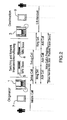
- Figure 2 is a message flow diagram showing call establishment for the system of Figure 1;
- Figure 3 is a message flow diagram showing buffered PDA to PDA beaming of data for the system of Figure 1;
- Figure 4 is a message flow diagram showing non-buffered PDA to PDA beaming of data for the system of Figure 1; and
- Figure 5 is a message flow diagram showing server-mediated PDA to PDA beaming of data according to an alternative embodiment of the invention.
-
- As shown in Figure 1, an exemplary embodiment of the system according to the present invention comprises two network portals 1 and 3 (e.g. Mitel Network Portal IP telephony devices) connected to
respective ICPs 5 and 6 (e.g. Mitel Networks 3100 Integrated Communications Platform). For purposes of illustration, only a single telephony device or network portal is shown connected to each ICP whereas, in fact, there would normally be multiple such devices. Eachnetwork portal 1 and 3 supports the IrDA protocol to receive dialing commands fromrespective PDAs - While the present description is directed to IrDA protocol mechanisms, it will be understood that the present invention is not limited to IrDA protocol and other wireless protocols such as Bluetooth or 802.11, are also possible between phone and mobile device.
- The IrDA protocol works on a master/slave basis whereby communications are sent between two devices (such as
PDAs 7 and 9). According to the present invention, eachnetwork portal 1 and 3 acts as a proxy on behalf of the associated PDA. - LAN A, LAN B and the WAN provide QoS networking/routing in a well known manner, and have no real bearing on the present invention.
- With reference to Figure 2, the user of PDA 7 (referred to hereinafter as the Originator) first places a voice call to the user of PDA 9 (referred to hereinafter as the Destination). Once the call is established, voice communication is effected over IP (RTP/UDP) across LANs A and B and the WAN, between the user's
telephony devices 1 and 3. - As shown in Figure 3, when the Originator initiates an object exchange, the network portal 1 accepts the connection on behalf of the Destination. The
network portals 1 and 3 at either end communicate their capabilities (mainly, whether they support IrDA transfers). If this is not acknowledged at both ends, PDA to PDA transfer is refused (e.g. a message is displayed on thenetwork portals 1 and 3 and the IrDA connection is closed). Thus, IrDA handshaking determines the capabilities of both devices and establishes the master/slave (primary/secondary in IrDA terms) roles. - When the network portal 1 recognizes an incoming IrDA exchange, a TCP socket is opened to the Destination's
network portal 3. TheOriginator PDA 7 attempts to establish communication toPDA 9 by taking on the role of master (primary) and initiates handshaking with the Destination'sPDA 9. - Once connections at both ends have been established and acknowledged, the object is sent by the Originator's PDA 7 (i.e. beaming a file) within the range for a local IrDA exchange, to the Originator's network portal 1. The network portal 1 uses the secondary role of the IrDA stack to handshake with the PDA 7 (exchange IR capabilities for speed, timeouts, etc...). When handshaking completes, the
PDA 7 sends the object to the network portal 1 where it is cached. The network portal 1 andPDA 7 then disconnect with a success message. - The Originator's network portal 1 then makes a socket call to the Destination's
network portal 3 on a predetermined listening port. Both network portals acknowledge the pending IrDA exchange. The object(s) are packetized by the network portal 1 and then transferred to the Destination'snetwork portal 3 over LAN A, the WAN and LAN B.
When theDestination network portal 3 receives the complete file it uses the primary role of the IrDA stack to detect and initiate handshaking with the Destination'sPDA 9. If thePDA 9 is detected, the file is beamed to thePDA 9 and an acknowledgment is returned to the Originating network portal's display during the socket closure. - In some environments, it is possible that the network portal 1 of the preferred embodiment may have insufficient memory to buffer a file before it is sent to the Destination. In such instances, the object can be streamed to the
Destination PDA 9 while being received at the Originator's network portal 1. - For example, in the alternative embodiment of Figure 4, the Originator's network portal 1 "stalls" the Originator's
PDA 7 by using empty IrDA retransmission frames until the acknowledgement from theDestination network portal 3 that aPDA 9 exists and is connected. As soon as this acknowledgement is received, each subsequently received IrDA frame is transmitted immediately to theDestination network portal 3 and beamed to thePDA 9. Error messages that are within the higher stack layers are returned to the Originator's network portal 1 for re-sending by thePDA 7. - Once the transfer is complete, an acknowledgment is returned to the Originating network portal's display during the socket closure.
- For IrDA to operate smoothly without timeout problems, it is necessary for the network portals to "buffer" the incoming request while trying to establish the destination link. Thus, with reference to the alternative embodiment of Figure 5, server mediated transfers can be conducted via a
server 11 or "mediator" for accepting, buffering and relaying the object on behalf of eithernetwork portal 1 or 3. - During the exchange of IrDA capabilities between the two
network portals 1 and 3, the IP address of themediator 11 is provided by thenetwork portal 1 or 3 that cannot support buffered or streamed data. If both network portals report a mediator, the IP of the mediator from the network portal that originated the voice call is chosen. - In the embodiment of Figure 5, both the Originator and Destination communicate only with the
mediator 11. The Originator's network portal 1 transmits the entire file to themediator 11 which, once the file is received successfully, then relays the file to theDestination network portal 3. Once theDestination network portal 3 successfully delivers the file to theDestination PDA 9, a message is displayed on the Originating network portal 1. - While the embodiments discussed herein are directed to particular implementations of the present invention, it will be apparent that additional variations and modifications to these embodiments are within the scope of the invention as defined solely by the claims appended hereto.
Claims (15)
- A method of transferring data over a network from a first portable electronic device to a second portable electronic device comprising the steps of:establishing a voice-call path between first and second telephony devices by initiating a voice-call connection from one of said first and second telephony devices to the other of said first and second telephony devices, the first and second telephony devices having first and second network portals, respectively;initiating a data exchange from one of said first and second portable electronic devices to the other of said first and second portable electronic devices, each of said first and second portable electronic devices including an infrared interface;sending the data from said first portable electronic device to said first network portal via infrared communication;sending the data from said first network portal of the first telephony device to the second network portal of the second telephony device via said network; andsending the data from said second network portal to said other of said first and second portable electronic devices via infrared communication.
- The method of claim 1, wherein said voice communication path is provided over a TCP socket using TCP/IP.
- The method of claim 1 or claim 2, wherein said step of initiating said data exchange includes IrDA handshaking between said one of said portable electronic devices and said first network portal, and said other of said portable electronic devices and said second network portal for determining IrDA capabilities and establishing primary/secondary IrDA roles there between.
- The method of any one of claims 1 to 3, further comprising the step of buffering said data in said first network portal before sending said data to said second network portal.
- The method of any one of claims 1 to 4, wherein said data is streamed to the other one of said portable electronic devices from said first network portal via said second network portal.
- The method of claim 5, wherein said first network portal delays the sending of data from said one of said portable electronic devices by using empty IrDA retransmission frames pending receipt of an acknowledgement from said second network portal that said other one of said portable electronic devices is ready to receive said data, whereupon each subsequent IrDA frame of said data sent by said one of said portable electronic devices is transmitted immediately to said second network portal and beamed therefrom to said other one of said portable electronic devices.
- The method of any one of claims 1 to 6, wherein said step of sending the data from said first network portal to said second network portal further includes transmitting said data in its entirety from said first network portal to a mediator which in response to receipt of the data relays said data to said second network portal.
- A system for transferring data over a network from a first portable electronic device to a second portable electronic device comprising:first and second telephony devices for initiating a voice-call connection from one of said first and second telephony devices to the other of said first and second telephony devices, the first and second telephony devices having first and second network portals, respectively,the first network portal of the first telephony device having an infrared interface for receiving said data beamed from said first portable electronic device via infrared communication after said voice-call is established, and in response transmitting said data over the network,the second network portal of the second telephony device for receiving the data from said network, and beaming said data to said second portable electronic device via a further infrared interface, whereby said data is transferred from said first to said second portable electronic device through said telephony devices, after said voice call connection is established.
- The system of claim 8, wherein said voice call is provided over a TCP socket using TCP/IP.
- The system of claim 9, wherein said network includes at least one Integrated Communications Platform connected between the IP telephony devices.
- The system of any one of claims 8 to 10, wherein each of said first and second network portals supports IrDA protocol for receiving dialing commands from respective ones of said first and second portable electronic device using the OBEX (Object Exchange) application layer at the top of the IrDA protocol stack.
- The system of any one of claims 8 to 11, wherein said first network portal includes a cache for buffering the data prior to transmission over said network.
- The system of any one of claims 8 to 12, wherein said data is streamed to said second portable electronic device from said first network portal via said second network portal.
- The system of any one of claims 8 to 12, wherein said first network portal includes a cache for buffering said data beamed from said first portable electronic device using empty IrDA retransmission frames pending receipt of an acknowledgement from said second network portal that said second portable electronic device is ready to receive said data, whereupon each IrDA frame of said data sent by said first portable electronic device is transmitted immediately to said second network portal and beamed to said second portable electronic device.
- The system of any one of claims 8 to 14, further including a mediator server for receiving said data in its entirety from said first network portal and in response relaying said data to said second network portal.
Applications Claiming Priority (2)
| Application Number | Priority Date | Filing Date | Title |
|---|---|---|---|
| GBGB0307861.5A GB0307861D0 (en) | 2003-04-04 | 2003-04-04 | System and method for pda to pda communication using a network portal |
| GB0307861 | 2003-04-04 |
Publications (2)
| Publication Number | Publication Date |
|---|---|
| EP1465387A1 true EP1465387A1 (en) | 2004-10-06 |
| EP1465387B1 EP1465387B1 (en) | 2008-03-26 |
Family
ID=9956224
Family Applications (1)
| Application Number | Title | Priority Date | Filing Date |
|---|---|---|---|
| EP04252024A Expired - Lifetime EP1465387B1 (en) | 2003-04-04 | 2004-04-05 | System and method for PDA to PDA communication using a network portal |
Country Status (5)
| Country | Link |
|---|---|
| US (1) | US7529227B2 (en) |
| EP (1) | EP1465387B1 (en) |
| CA (1) | CA2463013C (en) |
| DE (1) | DE602004012643T2 (en) |
| GB (1) | GB0307861D0 (en) |
Families Citing this family (10)
| Publication number | Priority date | Publication date | Assignee | Title |
|---|---|---|---|---|
| US8036244B2 (en) * | 2004-08-06 | 2011-10-11 | Sharp Kabushiki Kaisha | Transmitter, receiver, communication system, communication method, non-transitory computer readable medium |
| US7787391B2 (en) * | 2005-01-28 | 2010-08-31 | Sharp Kabushiki Kaisha | Communication device, communication system, communication method, communication program, and communication circuit |
| KR100902341B1 (en) * | 2005-01-28 | 2009-06-12 | 샤프 가부시키가이샤 | Communication device, communication system, communication method, computer-readable recording media having communication program recorded therein, and communication circuit |
| US8291273B2 (en) * | 2005-01-28 | 2012-10-16 | Sharp Kabushiki Kaisha | Communication device, non-transitory computer-readable medium storing a communication program |
| US8051182B2 (en) * | 2005-01-28 | 2011-11-01 | Sharp Kabushiki Kaisha | Communication device, communication system, communication method, communication program, and communication circuit |
| JP4786664B2 (en) * | 2005-11-10 | 2011-10-05 | シャープ株式会社 | DATA TRANSMITTING DEVICE AND ITS CONTROL METHOD, DATA TRANSMITTING DEVICE CONTROL PROGRAM, AND RECORDING MEDIUM CONTAINING THE PROGRAM |
| US7962159B2 (en) * | 2006-04-25 | 2011-06-14 | International Business Machines Corporation | Method and system for receiving data on a portable device |
| JP4219950B2 (en) * | 2006-10-16 | 2009-02-04 | シャープ株式会社 | COMMUNICATION DEVICE, COMMUNICATION METHOD, COMMUNICATION CIRCUIT, MOBILE PHONE, PROGRAM, AND COMPUTER-READABLE RECORDING MEDIUM CONTAINING THE PROGRAM |
| JP5272536B2 (en) * | 2008-06-25 | 2013-08-28 | 富士通株式会社 | Call relay method and call relay system |
| US9973305B2 (en) | 2014-12-30 | 2018-05-15 | Mediatek Inc. | Soft buffer partition for superposition coding |
Citations (5)
| Publication number | Priority date | Publication date | Assignee | Title |
|---|---|---|---|---|
| WO2001024503A1 (en) * | 1999-09-27 | 2001-04-05 | 3Com Corporation | System and method for interconnecting portable information devices (pdas) through a daa telephony system |
| WO2001097457A1 (en) * | 2000-06-13 | 2001-12-20 | Red-M (Communications) Limited | Call handling device for connecting a wireless communications device to a communications network |
| US6336142B1 (en) * | 1997-06-02 | 2002-01-01 | International Business Machines Corporation | Methods and apparatus for downloading data between an information processing device and an external device via a wireless communications technique |
| CA2369383A1 (en) | 2001-01-27 | 2002-07-27 | Mitel Knowledge Corporation | Transport protocols for application platforms over network portals |
| EP1271885A2 (en) * | 2001-06-29 | 2003-01-02 | Nokia Corporation | Apparatus, method and system for an object exchange bridge |
Family Cites Families (9)
| Publication number | Priority date | Publication date | Assignee | Title |
|---|---|---|---|---|
| US4221932A (en) * | 1978-11-02 | 1980-09-09 | Bell Telephone Laboratories, Incorporated | Infrared remote signaling system |
| JP2511591B2 (en) | 1990-10-29 | 1996-06-26 | インターナショナル・ビジネス・マシーンズ・コーポレイション | Wireless optical communication system operating method and optical communication system |
| US5461627A (en) * | 1991-12-24 | 1995-10-24 | Rypinski; Chandos A. | Access protocol for a common channel wireless network |
| EP0878936A3 (en) | 1997-05-12 | 2001-01-24 | Victor Company Of Japan, Limited | Communication system and circuit controller |
| US6081356A (en) * | 1997-05-27 | 2000-06-27 | Steelcase Development Inc. | Integrated optical ports |
| US20030069996A1 (en) | 1999-08-30 | 2003-04-10 | William M. Parrott | Infrared to radio frequency adapter and method for using the same |
| US7203425B1 (en) | 2000-07-21 | 2007-04-10 | Texas Instruments Incorporated | Optical wireless link |
| JP3508060B2 (en) | 2000-10-27 | 2004-03-22 | 日本電気エンジニアリング株式会社 | Infrared communication method |
| WO2003007162A1 (en) | 2001-07-13 | 2003-01-23 | Adalive.Com, Inc. | Interactive communications system coupled to portable computing devices using short range communications |
-
2003
- 2003-04-04 GB GBGB0307861.5A patent/GB0307861D0/en not_active Ceased
-
2004
- 2004-04-01 CA CA002463013A patent/CA2463013C/en not_active Expired - Lifetime
- 2004-04-02 US US10/815,804 patent/US7529227B2/en active Active
- 2004-04-05 DE DE602004012643T patent/DE602004012643T2/en not_active Expired - Lifetime
- 2004-04-05 EP EP04252024A patent/EP1465387B1/en not_active Expired - Lifetime
Patent Citations (5)
| Publication number | Priority date | Publication date | Assignee | Title |
|---|---|---|---|---|
| US6336142B1 (en) * | 1997-06-02 | 2002-01-01 | International Business Machines Corporation | Methods and apparatus for downloading data between an information processing device and an external device via a wireless communications technique |
| WO2001024503A1 (en) * | 1999-09-27 | 2001-04-05 | 3Com Corporation | System and method for interconnecting portable information devices (pdas) through a daa telephony system |
| WO2001097457A1 (en) * | 2000-06-13 | 2001-12-20 | Red-M (Communications) Limited | Call handling device for connecting a wireless communications device to a communications network |
| CA2369383A1 (en) | 2001-01-27 | 2002-07-27 | Mitel Knowledge Corporation | Transport protocols for application platforms over network portals |
| EP1271885A2 (en) * | 2001-06-29 | 2003-01-02 | Nokia Corporation | Apparatus, method and system for an object exchange bridge |
Also Published As
| Publication number | Publication date |
|---|---|
| EP1465387B1 (en) | 2008-03-26 |
| GB0307861D0 (en) | 2003-05-14 |
| DE602004012643D1 (en) | 2008-05-08 |
| US20040228332A1 (en) | 2004-11-18 |
| DE602004012643T2 (en) | 2008-07-17 |
| CA2463013C (en) | 2008-09-09 |
| CA2463013A1 (en) | 2004-10-04 |
| US7529227B2 (en) | 2009-05-05 |
Similar Documents
| Publication | Publication Date | Title |
|---|---|---|
| JP3758999B2 (en) | Data communication method | |
| KR100498932B1 (en) | Apparatus and method for session establishment in radio network organized mobile nodes | |
| EP1137238A2 (en) | System and method for integrated communications over a local IP network | |
| JP5116398B2 (en) | COMMUNICATION DEVICE, RADIO COMMUNICATION DEVICE, AND COMMUNICATION CONTROL METHOD | |
| CN100512460C (en) | System and method for delivering private network features to a public network | |
| EP1393497B1 (en) | Dual mode service platform within network communication system | |
| CN101455117A (en) | Mobile terminal and communication method | |
| EP1385323A1 (en) | A system, a method and apparatus for peer-to peer exchange of information | |
| CN100484170C (en) | Extended handset function and mobility | |
| WO2009039891A1 (en) | Method of controlling a communication device | |
| CA2463013C (en) | System and method for pda to pda communication using a network portal | |
| KR100382862B1 (en) | Internet telephony system using distributed call processing techique based on sip protocol and method thereof | |
| CN101142803A (en) | Communication system enabling at least two handheld devices to join network service | |
| JP3791504B2 (en) | Information processing system and information processing method | |
| JP4891569B2 (en) | Method and apparatus for low latency, high accuracy peak display and call abandonment | |
| CN102037715A (en) | Communication system and mobile phone using IP telephony on license-free frequencies | |
| US7203757B2 (en) | Device, method and program for protocol translation | |
| JP5000432B2 (en) | Communication apparatus and communication control method | |
| CA2369383C (en) | Transport protocols for application platforms over network portals | |
| JP5769909B2 (en) | Wireless communication apparatus and server apparatus | |
| EP1798935A1 (en) | Alarm and messaging communications system having wireless network gateway | |
| JP3665309B2 (en) | COMMUNICATION SYSTEM, COMMUNICATION DEVICE, AND COMMUNICATION METHOD | |
| KR20040104775A (en) | Apparatus and Method for efficient re-transmission of packets between different networks | |
| US12526226B2 (en) | MP-DCCP proxy to enable multipath transmission of DCCP data packets between a sender and a receiver | |
| JP3515465B2 (en) | Mobile device, mobile communication system and communication control method |
Legal Events
| Date | Code | Title | Description |
|---|---|---|---|
| PUAI | Public reference made under article 153(3) epc to a published international application that has entered the european phase |
Free format text: ORIGINAL CODE: 0009012 |
|
| 17P | Request for examination filed |
Effective date: 20040504 |
|
| AK | Designated contracting states |
Kind code of ref document: A1 Designated state(s): AT BE BG CH CY CZ DE DK EE ES FI FR GB GR HU IE IT LI LU MC NL PL PT RO SE SI SK TR |
|
| AX | Request for extension of the european patent |
Extension state: AL HR LT LV MK |
|
| AKX | Designation fees paid |
Designated state(s): DE FR GB |
|
| 17Q | First examination report despatched |
Effective date: 20050721 |
|
| GRAP | Despatch of communication of intention to grant a patent |
Free format text: ORIGINAL CODE: EPIDOSNIGR1 |
|
| GRAS | Grant fee paid |
Free format text: ORIGINAL CODE: EPIDOSNIGR3 |
|
| GRAA | (expected) grant |
Free format text: ORIGINAL CODE: 0009210 |
|
| RAP1 | Party data changed (applicant data changed or rights of an application transferred) |
Owner name: CELTIC TECH JET LIMITED |
|
| RAP1 | Party data changed (applicant data changed or rights of an application transferred) |
Owner name: MITEL NETWORKS CORPORATION |
|
| AK | Designated contracting states |
Kind code of ref document: B1 Designated state(s): DE FR GB |
|
| REG | Reference to a national code |
Ref country code: GB Ref legal event code: FG4D |
|
| REF | Corresponds to: |
Ref document number: 602004012643 Country of ref document: DE Date of ref document: 20080508 Kind code of ref document: P |
|
| ET | Fr: translation filed | ||
| PLBE | No opposition filed within time limit |
Free format text: ORIGINAL CODE: 0009261 |
|
| STAA | Information on the status of an ep patent application or granted ep patent |
Free format text: STATUS: NO OPPOSITION FILED WITHIN TIME LIMIT |
|
| 26N | No opposition filed |
Effective date: 20081230 |
|
| REG | Reference to a national code |
Ref country code: FR Ref legal event code: PLFP Year of fee payment: 13 |
|
| REG | Reference to a national code |
Ref country code: FR Ref legal event code: PLFP Year of fee payment: 14 |
|
| REG | Reference to a national code |
Ref country code: FR Ref legal event code: PLFP Year of fee payment: 15 |
|
| REG | Reference to a national code |
Ref country code: DE Ref legal event code: R079 Ref document number: 602004012643 Country of ref document: DE Free format text: PREVIOUS MAIN CLASS: H04L0029060000 Ipc: H04L0065000000 |
|
| PGFP | Annual fee paid to national office [announced via postgrant information from national office to epo] |
Ref country code: FR Payment date: 20230309 Year of fee payment: 20 |
|
| PGFP | Annual fee paid to national office [announced via postgrant information from national office to epo] |
Ref country code: GB Payment date: 20230302 Year of fee payment: 20 |
|
| PGFP | Annual fee paid to national office [announced via postgrant information from national office to epo] |
Ref country code: DE Payment date: 20230307 Year of fee payment: 20 |
|
| REG | Reference to a national code |
Ref country code: DE Ref legal event code: R071 Ref document number: 602004012643 Country of ref document: DE |
|
| REG | Reference to a national code |
Ref country code: GB Ref legal event code: PE20 Expiry date: 20240404 |
|
| PG25 | Lapsed in a contracting state [announced via postgrant information from national office to epo] |
Ref country code: GB Free format text: LAPSE BECAUSE OF EXPIRATION OF PROTECTION Effective date: 20240404 |
|
| PG25 | Lapsed in a contracting state [announced via postgrant information from national office to epo] |
Ref country code: GB Free format text: LAPSE BECAUSE OF EXPIRATION OF PROTECTION Effective date: 20240404 |