EP1465294A2 - A connection device for switches - Google Patents
A connection device for switches Download PDFInfo
- Publication number
- EP1465294A2 EP1465294A2 EP04075991A EP04075991A EP1465294A2 EP 1465294 A2 EP1465294 A2 EP 1465294A2 EP 04075991 A EP04075991 A EP 04075991A EP 04075991 A EP04075991 A EP 04075991A EP 1465294 A2 EP1465294 A2 EP 1465294A2
- Authority
- EP
- European Patent Office
- Prior art keywords
- modular unit
- safety
- seat
- arm
- protection
- Prior art date
- Legal status (The legal status is an assumption and is not a legal conclusion. Google has not performed a legal analysis and makes no representation as to the accuracy of the status listed.)
- Granted
Links
Images


Classifications
-
- H—ELECTRICITY
- H01—ELECTRIC ELEMENTS
- H01R—ELECTRICALLY-CONDUCTIVE CONNECTIONS; STRUCTURAL ASSOCIATIONS OF A PLURALITY OF MUTUALLY-INSULATED ELECTRICAL CONNECTING ELEMENTS; COUPLING DEVICES; CURRENT COLLECTORS
- H01R13/00—Details of coupling devices of the kinds covered by groups H01R12/70 or H01R24/00 - H01R33/00
- H01R13/46—Bases; Cases
- H01R13/514—Bases; Cases composed as a modular blocks or assembly, i.e. composed of co-operating parts provided with contact members or holding contact members between them
-
- H—ELECTRICITY
- H01—ELECTRIC ELEMENTS
- H01R—ELECTRICALLY-CONDUCTIVE CONNECTIONS; STRUCTURAL ASSOCIATIONS OF A PLURALITY OF MUTUALLY-INSULATED ELECTRICAL CONNECTING ELEMENTS; COUPLING DEVICES; CURRENT COLLECTORS
- H01R9/00—Structural associations of a plurality of mutually-insulated electrical connecting elements, e.g. terminal strips or terminal blocks; Terminals or binding posts mounted upon a base or in a case; Bases therefor
- H01R9/22—Bases, e.g. strip, block, panel
- H01R9/24—Terminal blocks
- H01R9/2425—Structural association with built-in components
- H01R9/2433—Structural association with built-in components with built-in switch
Definitions
- the present invention relates to a connection device for switches, and in particular to a blocking and safety device for assembly of modular units containing electrical devices designed, for example, for protecting electrical networks.
- connections of the above type is provided, for instance, by protection devices associated to low-voltage electrical networks, i.e., with operating voltages of up to approximately 1000 V.
- These systems usually comprise a first modular unit containing a differential block, or else another protection unit, capable of actuating, in the case of faulty operation of the electrical network, a circuit breaker contained in a second modular unit associated to the first one.
- connection of modular units of the aforesaid type is regulated by precise standards and must hence meet certain safety requirements.
- the current standard envisages that the assembly of said units must be non-removable and built in such a way that any attempt at tampering will leave evident traces and irreversible damage, where by "assembly" of the two parts is meant both the mechanical coupling and the electrical coupling.
- a third requirement imposed further concerns the electrical connections of the two parts in contact, which must be protected and adequately insulated.
- connection of the two parts is obtained by means of a transverse cover or lid fixed to one of the two units by means of pins, having fork-shaped ends.
- the electrical connections between the two units are external to the units themselves and, for this reason, the cover is also designed to provide a guide and protection of said connections.
- the engagement systems currently used for connection of the modular units do not always enable a secure engagement and, for this reason, they must often be integrated with anti-tampering systems designed to prevent any possible external tampering, anti-tampering systems being obtained, for example, by sealing means or use of covers similar to the one described above.
- the primary task of the present invention is to provide a safety device for connection of modular units which will enable a secure engagement of the parts, in conformance with the requirements envisaged by current standards.
- one of the purposes of the present invention is to provide a connection device on which any external tampering is prevented, but which, at the same time, can be applied to the aforesaid modules with extreme ease by technicians qualified to carry out assembly of said modular units.
- Another purpose of the present invention is to provide a connection device which cannot be actuated accidentally prior to being set in place, for the purpose of preserving functionality of the device itself and of the modular unit to which it is associated.
- a further task of the present invention is to provide modular units, for example, for protection of electrical networks, which will be easily coupled together.
- one of the purposes of the present invention is to provide modular units, in which the constituent parts and the anchoring means associated thereto will have a shape that is relatively simple and hence easy to produce.
- a further task of what forms the subject of the present invention is to provide a protection device for electrical networks formed by two or more modular units, coupling of which can be readily achieved and meets the standards in question.
- Not the least important purpose of the present invention is to provide a safety device for connection of modular units containing electrical devices that will present high reliability, relative ease of construction, and competitive costs.
- a blocking and safety device for connection of one first and one second modular units containing electrical devices;
- the device is characterized in that it comprises two distinct elements which can be inserted inside said modular units in a non-removable way, it being possible for one first of said elements to be inserted inside said first modular unit, and for the second one of said elements to be inserted inside both of said modular units.
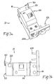
- the blocking and safety device 1 comprises two distinct elements, which can be inserted within two modular units in a non-removable way.
- a first element 20 can only be inserted within a first modular unit 21, whilst the second element 30 can be inserted both into said first modular unit 21 and into a second modular unit 31 associated to the former.
- the first element 20 preferably has a substantially prismatic shape, preferably with a square base, as may be seen in Figures 1a and 2a.
- Made in said first element 20 is a cavity 22, within which it is possible to insert at least one portion of the second element 30.
- said cavity 22 has a substantially prismatic shape and dimensions such as to be able to house one end of the second element 30 (see Figure 2a).
- the first element 20 is advantageously provided with anti-extraction means designed to prevent extraction once insertion of the first element itself into the first modular unit 21 is completed.
- said anti-extraction means are made, for example, through at least one tooth-like end 25 projecting from the central body of the element itself.
- the first element 20 is, in an initial step, partially inserted into the first modular unit 21, whilst it is completely inserted inside it only subsequently, in a step coinciding with the final setting-in-place of the blocking and safety device 1.
- said first element 20 is preferably equipped also with arrest means which prevent a relative movement of the first element 20 with respect to said modular unit 21 in the interval between the two insertion steps referred to above.
- said arrest means can coincide with the tooth-like end 25, which, by co-operating with the elastic walls forming the seat in which the first element 20 is inserted, enables a position of stable equilibrium to be maintained between the two parts.
- the tooth-like end 25 can be advantageously shaped so as to oppose itself to motion, thus rendering necessary an additional thrust to enable complete insertion of the first element 20 within the first modular unit 21.
- the end 25 prevents movement of the element 20 in an opposite direction, through coupling with appropriate seats made in the first modular unit 21, as described in what follows.
- the second component 30 has, instead, a structure from which there extend a first arm 33 and a second arm 34 in two directions considerably different from one another.
- the first arm 33 extends in a direction substantially orthogonal to that in which the second arm 34 extends; in addition, with reference to what has been indicated above, the first arm 33, preferably in its end part 35, can be inserted into the cavity 22 made on the first element 20.
- the second element 30 comprises anti-extraction means, which prevent motion of the element itself in substantially the same direction as that of insertion but in the opposite sense.
- the invention further envisages the presence of appropriate engagement means associated to said second element 30, which are capable of ensuring a stable connection of the element itself to both of the modular units.
- said anti-extraction means belonging to the second element 30 comprise shaped tabs 36 projecting from the central part of said first arm 33, whilst said engagement means comprise, instead, a fork-shaped part 38 associated to the end of said first arm 33.
- the two arms of the fork 38 have, in their terminal part, two tooth-like shapings 39, which enable engagement of the second element 30 to the first modular unit 21.
- said engagement means also comprise a hook-shaped end 37 associated to the terminal part of the second arm 34, which enables connection of the second element 30 with the second modular unit 31.
- the second element 30 is also provided with guide means designed to facilitate a correct and stable insertion of the element itself within the two modular units to which it is associated.
- said guide means comprise a guide side wall 41, which is associated to said first arm 33 and has a shape such that at least one terminal portion also can be inserted into said cavity 22 made on the first element 20.
- the shape of the components forming the blocking and safety device 1 appears very simple and hence of easy construction but, at the same time, is provided with all the means necessary for ensuring operation and safety of the device itself.
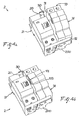
- the present invention relates also to a modular unit 21, as may be seen in Figure 3a, which comprises: a front surface 51; a rear surface 52; two side surfaces 53 and 54; a top surface 55; and a bottom surface 56.
- Said modular unit 21 is characterized in that it comprises one first seat 70, designed for insertion of said first element 20, and one second seat 80, designed for insertion of said second element 30.
- the two seats 70 and 80 are in communication with one another, and, in particular, said first seat 70 is obtained in a position corresponding to one first surface belonging to the first modular unit 21, whilst the second seat 80 is obtained in a position corresponding to one second surface adjacent to said first surface.
- said first surface coincides with the front surface 51
- said second surface coincides with the top surface 55.
- FIGS. 1b and 2b show, moreover, how the seats 70 and 80 are provided with means for positioning and anchorage of the aforementioned anti-extraction means and/or of the engagement means belonging to both of the elements 20 and 30 forming the blocking and safety device 1.
- the above anchoring means preferably comprise internal projections and cavities appropriately shaped according to the type of anti-extraction and/or engagement means to be housed.
- the tooth-shaped ends 39, belonging to the terminal fork-shaped part 38 are anchored to appropriate projections 81 and are then fixedly blocked.
- the said projecting tabs 36 remain positioned behind corresponding projections 82, preventing in this way extraction of the second element 30.
- the present invention also relates to a protection and safety device 2 for electrical networks, which comprises one first modular unit 21, as described above, that can be coupled to a second modular unit 31 and which is characterized in that it comprises the blocking and safety device 1 as defined previously.
- a protection and safety device 2 made up in this way may, for example, comprise, inside said first modular unit 21, a protective electrical system of a differential type and, inside said second modular unit 31, a circuit-breaker system.
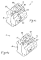
- Figure 4a shows the first step of joining of the two modular units forming the protection and safety device 2.
- the two elements 20 and 30 forming the blocking and safety device 1 are associated to the first modular unit and partially inserted therein through, respectively, the top surface 55 and the front surface 51, according to what has already been indicated above.
- Figure 4b shows, instead, a second step of joining of the two modular units. It may be noted how said joining occurs through the contact of a side surface 54 belonging to the first modular unit 21 with a second side surface 91 belonging to the second modular unit 31.
- the surfaces in contact are provided with mechanical and electrical coupling keys to enable mutual positioning and correct operation of the two parts.
- these latter systems comprise, respectively, coupling pins 101 and actuating mechanisms 102.
- Figure 4c shows the same step of joining of the two modular units as the one represented in Figure 4b according, however, to a different viewpoint which makes it possible to appreciate better the position of the two elements forming the blocking and safety device 1, as well as the position of the corresponding seats made in the two modular units.
- Figure 4d shows, instead, the complete joining of the two modular units 21 and 31 through the blocking and safety device 1 according to the invention. It may be noted how, at the end of joining, both of the elements 20 and 30 making up the blocking and safety device 1 are completely inserted inside the two modular units 21 and 31 in a non-removable way on account of the engagement and/or anti-extraction means so as to rendering any attempt of external tampering rather evident.
- the invention preferably envisages also that the two modular units 21 and 31 are coupled through a transverse element 200 preferably provided with electrical coupling keys.
- said transverse element is stably engaged to the first modular unit 21 through the bottom surface 56 and is provided with electrical connections 103, which can be appropriately coupled, via the bottom surface 92, to the connection terminals belonging to the second modular unit 31.
- the second modular unit 31 further comprises a third seat 100, which, as may be seen in Figure 4c, is made on a third surface 93 belonging to said second modular unit 31 and is substantially adjacent, according to a preferred embodiment previously indicated, to the top surface 55 of the first modular unit 21.
- the second element 30, through the second transverse arm 34, enables a transverse connection of the two modular units 21 and 31 so ensuring mutual positioning thereof.
- Figures 1b and 2b show precisely the position of the two elements 20 and 30 before and after the last step of insertion into the first modular unit.
- first element 20 Only a vertical displacement of the first element 20 will enable horizontal displacement of the second element 30 and hence its complete insertion.
- the second element 30 can be inserted right in, and hence blocked, within the corresponding seat 80 only when the first element 20 is completely inserted into the corresponding seat 70.
- the technical solutions adopted for the blocking and safety device according to the invention enable the pre-set tasks and purposes to be fully achieved.
- the blocking device is in conformance with the requirements imposed by the standards concerning safety.
- the operating principle and the compulsory sequence of insertion of the two elements forming the device moreover afford a guarantee against any attempt at external tampering, as well as providing a tool for prevention against any possible losses of functionality deriving from accidental impact or falling of the modular units.
- the simple shape of the constituent elements and of the corresponding coupling seats made enables limitation of production costs, at the same time guaranteeing a high degree of functionality of the device.
Landscapes
- Details Of Connecting Devices For Male And Female Coupling (AREA)
- Push-Button Switches (AREA)
- Connector Housings Or Holding Contact Members (AREA)
Abstract
Description
- Figure 1 a is a perspective view of the blocking and safety device according to the invention prior to assembly of the two modular units;
- Figure 1 bis a view in situ of the blocking and safety device according to the invention associated to a first modular unit prior to assembly of the second modular unit;
- Figure 2a is a perspective view of the safety device according to the invention after assembly of the two modular units;
- Figure 2b is a view in situ of the safety device according to the invention associated to a first modular unit after assembly of the two modular units;
- Figure 3a is a perspective view of the first modular unit and of the blocking and safety device according to the invention associated thereto;
- Figure 3b is a plan view of the first modular unit and of the blocking and safety device according to the invention associated thereto;
- Figure 4a is a perspective view of a first step of assembly of the two modular units and of the corresponding blocking and safety device according to the invention;
- Figure 4b is a perspective view of a second step of assembly of the two modular units and of the corresponding blocking and safety device according to the invention;
- Figure 4c is a perspective view of a second step of assembly of the two modular units and of the corresponding blocking and safety device according to the invention viewed from a viewpoint different from the one used for Figures 4a and 4b;
- Figure 4d is a perspective view at the end of assembly of the two modular units and of the corresponding blocking and safety device according to the invention, with respect to the same viewpoint as the one used for Figure 4c.
Claims (24)
- A safety and blocking device (1) for connection of a first modular unit (21) and a second modular unit (31) containing electrical devices, characterized in that it comprises two distinct elements, which can be inserted inside said modular units in a non-removable way, the first (20) of said elements being insertable inside said first modular unit (21), and the second (30) of said elements being insertable inside both of said modular units (21, 31).
- The safety and blocking device (1) according to claim 1, characterized in that said first element (20) has a substantially prismatic shape, with a cavity (22) designed for insertion of said second element (30).
- The safety and blocking device (1) according to claim 1 or 2, characterized in that said first element (20) comprises anti-extraction means to prevent extraction from said first modular unit (21), and/or arrest means for maintaining a position of partial insertion of said first element (20) in said first modular unit (21).
- The safety and blocking device (1) according to claim 3, characterized in that said anti-extraction means and said arrest means comprise at least one tooth-like end (25) projecting from the central body of said first element (20).
- The safety and blocking device (1) according to one or more of the preceding claims 2 to 4, characterized in that said second element (30) is defined by a structure comprising a first arm (33) and a second arm (34), said first arm (33) being insertable inside said cavity (22) made on said first element (20).
- The safety and blocking device (1) according to claim 5, characterized in that the second arm (34) extends in a direction substantially orthogonal to that in which the first arm (33) extends.
- The safety and blocking device (1) according to claim 5 or 6, characterized in that said first arm (33) comprises anti-extraction means, and in that said first arm (33) and said second arm (34) comprise engagement means.
- The safety and blocking device (1) according to claim 7, characterized in that said anti-extraction means comprise shaped tabs (36) projecting from said first arm (33), and said engagement means comprise a fork-shaped part (38) associated to the end of said first arm (33), and a hook-shaped end (37) associated to the terminal part of the second arm (34), said fork-shaped part comprising, in the two branches of the fork, tooth-like shapings (39).
- The safety and blocking device (1) according to one or more of the preceding claims, characterized in that said second element (30) comprises guide means for guiding insertion.
- The safety and blocking device (1) according to claim 9, characterized in that said guide means comprise a side wall (41) associated to said first arm (33), said wall (41) being insertable, at one end thereof, inside said cavity (22) made on said first element (20).
- A modular unit (21) for protection and security devices for electrical networks, comprising a front surface (51), a rear surface (52), two side surfaces (53, 54), a top surface (55), and a bottom surface (56), said modular unit (21) being designed to be coupled with a second modular unit (31) and being characterized in that it comprises a first seat (70) and a second seat (80) for insertion of a first element (20) and a second element (30) of a safety and blocking device (1) according to one or more of the preceding claims.
- The modular unit (21) according to claim 11, characterized in that said first seat (70) is in communication with said second seat (80).
- The modular unit (21) according to claim 11 or 12, characterized in that said first seat (70) is obtained from a first surface of said first modular unit, and said second seat (80) is obtained from a second surface adjacent to said first surface.
- The modular unit (21) according to one or more of claims 11 to 13, characterized in that said first seat (70) and said second seat (80) comprise means for positioning and anchorage of said anti-extraction means and/or of the engagement means according to what is defined in claims 7 and 8.
- The modular unit (21) according to claim 14, characterized in that said systems for positioning and anchorage comprise projections (81) and internal cavities (82) geometrically conjugated to said engagement means and/or anti-extraction means to be housed.
- A protection and safety device (2) for electrical networks, comprising a first modular unit (21) according to one or more of claims 11 to 15, which can be coupled to a second modular unit (31) and is characterized in that it comprises a blocking and safety device (1) according to one or more of claims 1 to 10.
- The protection and safety device (2) according to claim 16, characterized in that coupling of said modular units (21, 31) is carried out through contact of a side surface (54) of said first modular unit (21) with a second surface (91) belonging to said second modular unit (31), said surfaces in contact being provided with mechanical and electrical coupling keys.
- The protection and safety device (2) according to claim 17, characterized in that said mechanical and electrical coupling keys comprise, respectively, coupling pins (101) and actuating mechanisms (102).
- The protection and safety device (2) according to claims 16 to 18,
characterized in that said modular units (21, 31) are coupled through a transverse element (200) preferably provided with electrical coupling keys. - The protection and safety device (2) according to claim 19, characterized in that said transverse element (200) is stably engaged to said first modular unit (21) through said bottom surface (56) and is provided with electrical connections (103), which can be appropriately coupled to corresponding connection terminals contained in said second modular unit (31).
- The protection and safety device (2) according to one or more of claims 16 to 20, characterized in that said second modular unit (31) comprises a third seat (100) for insertion of said second element (30), said third seat (100) being made on a third surface 92 belonging to said second modular unit (31) and substantially adjacent to said second surface (54).
- The protection and safety device (2) according to one or more of claims 16 to 21, characterized in that insertion of said first element (20) inside said first seat (70) precedes insertion of said second element (30) inside said second seat (80) and said third seat (100).
- The protection and safety device (2) according to claims 16 to 22, characterized in that said third seat (100) comprises shaped cavities for anchorage of said hook-like ends (37) of the second arm (34) of said second element (30).
- The protection and safety device (2) according to one or more of claims 16 to 23, characterized in that said first modular unit (21) comprises a protection electrical system of a differential type, and said second modular unit (31) comprises an electrical circuit breaker.
Applications Claiming Priority (2)
| Application Number | Priority Date | Filing Date | Title |
|---|---|---|---|
| ITBG20030024 ITBG20030024A1 (en) | 2003-04-04 | 2003-04-04 | CONNECTION DEVICE FOR SWITCHES. |
| ITBG20030024 | 2003-04-04 |
Publications (3)
| Publication Number | Publication Date |
|---|---|
| EP1465294A2 true EP1465294A2 (en) | 2004-10-06 |
| EP1465294A3 EP1465294A3 (en) | 2008-11-26 |
| EP1465294B1 EP1465294B1 (en) | 2016-06-01 |
Family
ID=32843879
Family Applications (1)
| Application Number | Title | Priority Date | Filing Date |
|---|---|---|---|
| EP04075991.2A Expired - Lifetime EP1465294B1 (en) | 2003-04-04 | 2004-04-01 | A connection device for switches |
Country Status (2)
| Country | Link |
|---|---|
| EP (1) | EP1465294B1 (en) |
| IT (1) | ITBG20030024A1 (en) |
Family Cites Families (2)
| Publication number | Priority date | Publication date | Assignee | Title |
|---|---|---|---|---|
| FR2640422B1 (en) * | 1988-12-14 | 1996-04-05 | Merlin Gerin | MODULAR ASSEMBLY OF A MULTIPOLAR DIFFERENTIAL CIRCUIT BREAKER |
| DE4403585A1 (en) * | 1994-02-05 | 1995-08-10 | Licentia Gmbh | Combination of two switching devices or other electrical modular devices |
-
2003
- 2003-04-04 IT ITBG20030024 patent/ITBG20030024A1/en unknown
-
2004
- 2004-04-01 EP EP04075991.2A patent/EP1465294B1/en not_active Expired - Lifetime
Also Published As
| Publication number | Publication date |
|---|---|
| EP1465294A3 (en) | 2008-11-26 |
| EP1465294B1 (en) | 2016-06-01 |
| ITBG20030024A1 (en) | 2004-10-05 |
Similar Documents
| Publication | Publication Date | Title |
|---|---|---|
| KR100840815B1 (en) | Electrical switchgear and assembly | |
| JP2015023034A (en) | Quick connect power connector | |
| US6361378B1 (en) | Connector with a side retainer | |
| EP1560298B1 (en) | A divided connector and connector assembly | |
| US20120021633A1 (en) | Connector | |
| JP4980342B2 (en) | Electrical connector with terminal position assurance mechanism | |
| TWI686835B (en) | Electrical switching apparatus and secondary disconnect assembly with cradle assembly alignment and positioning features therefor | |
| US7833044B2 (en) | Connection system and squib connector therefor | |
| EP1465294B1 (en) | A connection device for switches | |
| US7232342B2 (en) | Fuse cavity and electric junction box equipped therewith | |
| TWI683338B (en) | Electrical switching apparatus and secondary disconnect assembly with terminal retention and correction features therefor | |
| JPH06181078A (en) | Connector connection structure | |
| US6843668B2 (en) | Device for connecting an electrical load to an insulated power supply cable | |
| EP2709213B1 (en) | Safety device for electrical socket | |
| KR200318477Y1 (en) | Connector assembly for cars coupling as one body a number of pin | |
| EP2764584B1 (en) | Connector housing | |
| EP0986136B1 (en) | Safety connection device, particularly for modular electrical devices | |
| JP3269034B2 (en) | Electrical connector | |
| JPH04233120A (en) | Overload relay | |
| ES2877821T3 (en) | Plug-in connection and procedure for actuation of a plug-in connection in high-voltage applications | |
| WO2012123460A1 (en) | Plug element with strain relief organ | |
| NO145491B (en) | CONTACT DEVICE FOR CONNECTING PROTECTIVE EQUIPMENT FOR AN ELECTRIC ELECTRICAL IN-OPERATION, WITHOUT TRANSFER, WITH A TESTING DEVICE | |
| JP3171064B2 (en) | Connector with retainer | |
| KR200318480Y1 (en) | A locking structure of a connector assembly for cars | |
| JP2010009801A (en) | Connector |
Legal Events
| Date | Code | Title | Description |
|---|---|---|---|
| PUAI | Public reference made under article 153(3) epc to a published international application that has entered the european phase |
Free format text: ORIGINAL CODE: 0009012 |
|
| AK | Designated contracting states |
Kind code of ref document: A2 Designated state(s): AT BE BG CH CY CZ DE DK EE ES FI FR GB GR HU IE IT LI LU MC NL PL PT RO SE SI SK TR |
|
| AX | Request for extension of the european patent |
Extension state: AL HR LT LV MK |
|
| RAP1 | Party data changed (applicant data changed or rights of an application transferred) |
Owner name: ABB S.P.A. |
|
| PUAL | Search report despatched |
Free format text: ORIGINAL CODE: 0009013 |
|
| AK | Designated contracting states |
Kind code of ref document: A3 Designated state(s): AT BE BG CH CY CZ DE DK EE ES FI FR GB GR HU IE IT LI LU MC NL PL PT RO SE SI SK TR |
|
| AX | Request for extension of the european patent |
Extension state: AL HR LT LV MK |
|
| 17P | Request for examination filed |
Effective date: 20090511 |
|
| AKX | Designation fees paid |
Designated state(s): AT BE BG CH CY CZ DE DK EE ES FI FR GB GR HU IE IT LI LU MC NL PL PT RO SE SI SK TR |
|
| GRAP | Despatch of communication of intention to grant a patent |
Free format text: ORIGINAL CODE: EPIDOSNIGR1 |
|
| INTG | Intention to grant announced |
Effective date: 20151222 |
|
| GRAS | Grant fee paid |
Free format text: ORIGINAL CODE: EPIDOSNIGR3 |
|
| GRAA | (expected) grant |
Free format text: ORIGINAL CODE: 0009210 |
|
| AK | Designated contracting states |
Kind code of ref document: B1 Designated state(s): AT BE BG CH CY CZ DE DK EE ES FI FR GB GR HU IE IT LI LU MC NL PL PT RO SE SI SK TR |
|
| REG | Reference to a national code |
Ref country code: GB Ref legal event code: FG4D |
|
| REG | Reference to a national code |
Ref country code: DE Ref legal event code: R081 Ref document number: 602004049387 Country of ref document: DE Owner name: ABB SCHWEIZ AG, CH Free format text: FORMER OWNER: ABB SERVICE S.R.L., MAILAND/MILANO, IT |
|
| REG | Reference to a national code |
Ref country code: CH Ref legal event code: EP Ref country code: AT Ref legal event code: REF Ref document number: 804382 Country of ref document: AT Kind code of ref document: T Effective date: 20160615 |
|
| REG | Reference to a national code |
Ref country code: IE Ref legal event code: FG4D |
|
| REG | Reference to a national code |
Ref country code: DE Ref legal event code: R096 Ref document number: 602004049387 Country of ref document: DE |
|
| REG | Reference to a national code |
Ref country code: NL Ref legal event code: MP Effective date: 20160601 |
|
| PG25 | Lapsed in a contracting state [announced via postgrant information from national office to epo] |
Ref country code: FI Free format text: LAPSE BECAUSE OF FAILURE TO SUBMIT A TRANSLATION OF THE DESCRIPTION OR TO PAY THE FEE WITHIN THE PRESCRIBED TIME-LIMIT Effective date: 20160601 |
|
| REG | Reference to a national code |
Ref country code: AT Ref legal event code: MK05 Ref document number: 804382 Country of ref document: AT Kind code of ref document: T Effective date: 20160601 |
|
| PG25 | Lapsed in a contracting state [announced via postgrant information from national office to epo] |
Ref country code: GR Free format text: LAPSE BECAUSE OF FAILURE TO SUBMIT A TRANSLATION OF THE DESCRIPTION OR TO PAY THE FEE WITHIN THE PRESCRIBED TIME-LIMIT Effective date: 20160902 Ref country code: ES Free format text: LAPSE BECAUSE OF FAILURE TO SUBMIT A TRANSLATION OF THE DESCRIPTION OR TO PAY THE FEE WITHIN THE PRESCRIBED TIME-LIMIT Effective date: 20160601 Ref country code: SE Free format text: LAPSE BECAUSE OF FAILURE TO SUBMIT A TRANSLATION OF THE DESCRIPTION OR TO PAY THE FEE WITHIN THE PRESCRIBED TIME-LIMIT Effective date: 20160601 Ref country code: NL Free format text: LAPSE BECAUSE OF FAILURE TO SUBMIT A TRANSLATION OF THE DESCRIPTION OR TO PAY THE FEE WITHIN THE PRESCRIBED TIME-LIMIT Effective date: 20160601 |
|
| PG25 | Lapsed in a contracting state [announced via postgrant information from national office to epo] |
Ref country code: RO Free format text: LAPSE BECAUSE OF FAILURE TO SUBMIT A TRANSLATION OF THE DESCRIPTION OR TO PAY THE FEE WITHIN THE PRESCRIBED TIME-LIMIT Effective date: 20160601 Ref country code: EE Free format text: LAPSE BECAUSE OF FAILURE TO SUBMIT A TRANSLATION OF THE DESCRIPTION OR TO PAY THE FEE WITHIN THE PRESCRIBED TIME-LIMIT Effective date: 20160601 Ref country code: IT Free format text: LAPSE BECAUSE OF FAILURE TO SUBMIT A TRANSLATION OF THE DESCRIPTION OR TO PAY THE FEE WITHIN THE PRESCRIBED TIME-LIMIT Effective date: 20160601 Ref country code: CZ Free format text: LAPSE BECAUSE OF FAILURE TO SUBMIT A TRANSLATION OF THE DESCRIPTION OR TO PAY THE FEE WITHIN THE PRESCRIBED TIME-LIMIT Effective date: 20160601 Ref country code: SK Free format text: LAPSE BECAUSE OF FAILURE TO SUBMIT A TRANSLATION OF THE DESCRIPTION OR TO PAY THE FEE WITHIN THE PRESCRIBED TIME-LIMIT Effective date: 20160601 |
|
| PG25 | Lapsed in a contracting state [announced via postgrant information from national office to epo] |
Ref country code: PL Free format text: LAPSE BECAUSE OF FAILURE TO SUBMIT A TRANSLATION OF THE DESCRIPTION OR TO PAY THE FEE WITHIN THE PRESCRIBED TIME-LIMIT Effective date: 20160601 Ref country code: PT Free format text: LAPSE BECAUSE OF FAILURE TO SUBMIT A TRANSLATION OF THE DESCRIPTION OR TO PAY THE FEE WITHIN THE PRESCRIBED TIME-LIMIT Effective date: 20161003 Ref country code: BE Free format text: LAPSE BECAUSE OF FAILURE TO SUBMIT A TRANSLATION OF THE DESCRIPTION OR TO PAY THE FEE WITHIN THE PRESCRIBED TIME-LIMIT Effective date: 20160601 Ref country code: AT Free format text: LAPSE BECAUSE OF FAILURE TO SUBMIT A TRANSLATION OF THE DESCRIPTION OR TO PAY THE FEE WITHIN THE PRESCRIBED TIME-LIMIT Effective date: 20160601 |
|
| REG | Reference to a national code |
Ref country code: DE Ref legal event code: R097 Ref document number: 602004049387 Country of ref document: DE |
|
| PLBE | No opposition filed within time limit |
Free format text: ORIGINAL CODE: 0009261 |
|
| STAA | Information on the status of an ep patent application or granted ep patent |
Free format text: STATUS: NO OPPOSITION FILED WITHIN TIME LIMIT |
|
| REG | Reference to a national code |
Ref country code: FR Ref legal event code: PLFP Year of fee payment: 14 |
|
| 26N | No opposition filed |
Effective date: 20170302 |
|
| PG25 | Lapsed in a contracting state [announced via postgrant information from national office to epo] |
Ref country code: DK Free format text: LAPSE BECAUSE OF FAILURE TO SUBMIT A TRANSLATION OF THE DESCRIPTION OR TO PAY THE FEE WITHIN THE PRESCRIBED TIME-LIMIT Effective date: 20160601 Ref country code: SI Free format text: LAPSE BECAUSE OF FAILURE TO SUBMIT A TRANSLATION OF THE DESCRIPTION OR TO PAY THE FEE WITHIN THE PRESCRIBED TIME-LIMIT Effective date: 20160601 |
|
| REG | Reference to a national code |
Ref country code: CH Ref legal event code: PL |
|
| GBPC | Gb: european patent ceased through non-payment of renewal fee |
Effective date: 20170401 |
|
| REG | Reference to a national code |
Ref country code: IE Ref legal event code: MM4A |
|
| PG25 | Lapsed in a contracting state [announced via postgrant information from national office to epo] |
Ref country code: MC Free format text: LAPSE BECAUSE OF FAILURE TO SUBMIT A TRANSLATION OF THE DESCRIPTION OR TO PAY THE FEE WITHIN THE PRESCRIBED TIME-LIMIT Effective date: 20160601 |
|
| PG25 | Lapsed in a contracting state [announced via postgrant information from national office to epo] |
Ref country code: LI Free format text: LAPSE BECAUSE OF NON-PAYMENT OF DUE FEES Effective date: 20170430 Ref country code: CH Free format text: LAPSE BECAUSE OF NON-PAYMENT OF DUE FEES Effective date: 20170430 Ref country code: GB Free format text: LAPSE BECAUSE OF NON-PAYMENT OF DUE FEES Effective date: 20170401 Ref country code: LU Free format text: LAPSE BECAUSE OF NON-PAYMENT OF DUE FEES Effective date: 20170401 |
|
| REG | Reference to a national code |
Ref country code: FR Ref legal event code: PLFP Year of fee payment: 15 |
|
| PG25 | Lapsed in a contracting state [announced via postgrant information from national office to epo] |
Ref country code: IE Free format text: LAPSE BECAUSE OF NON-PAYMENT OF DUE FEES Effective date: 20170401 |
|
| PG25 | Lapsed in a contracting state [announced via postgrant information from national office to epo] |
Ref country code: HU Free format text: LAPSE BECAUSE OF FAILURE TO SUBMIT A TRANSLATION OF THE DESCRIPTION OR TO PAY THE FEE WITHIN THE PRESCRIBED TIME-LIMIT; INVALID AB INITIO Effective date: 20040401 |
|
| PG25 | Lapsed in a contracting state [announced via postgrant information from national office to epo] |
Ref country code: BG Free format text: LAPSE BECAUSE OF FAILURE TO SUBMIT A TRANSLATION OF THE DESCRIPTION OR TO PAY THE FEE WITHIN THE PRESCRIBED TIME-LIMIT Effective date: 20160601 |
|
| PG25 | Lapsed in a contracting state [announced via postgrant information from national office to epo] |
Ref country code: CY Free format text: LAPSE BECAUSE OF NON-PAYMENT OF DUE FEES Effective date: 20160601 |
|
| REG | Reference to a national code |
Ref country code: DE Ref legal event code: R082 Ref document number: 602004049387 Country of ref document: DE Representative=s name: KUHNEN & WACKER PATENT- UND RECHTSANWALTSBUERO, DE Ref country code: DE Ref legal event code: R081 Ref document number: 602004049387 Country of ref document: DE Owner name: ABB SCHWEIZ AG, CH Free format text: FORMER OWNER: ABB S.P.A., MILANO, IT |
|
| PG25 | Lapsed in a contracting state [announced via postgrant information from national office to epo] |
Ref country code: TR Free format text: LAPSE BECAUSE OF FAILURE TO SUBMIT A TRANSLATION OF THE DESCRIPTION OR TO PAY THE FEE WITHIN THE PRESCRIBED TIME-LIMIT Effective date: 20160601 |
|
| PGFP | Annual fee paid to national office [announced via postgrant information from national office to epo] |
Ref country code: FR Payment date: 20230420 Year of fee payment: 20 Ref country code: DE Payment date: 20230420 Year of fee payment: 20 |
|
| REG | Reference to a national code |
Ref country code: DE Ref legal event code: R071 Ref document number: 602004049387 Country of ref document: DE |