EP1465152A2 - Reverberation apparatus controllable by positional information of sound source - Google Patents
Reverberation apparatus controllable by positional information of sound source Download PDFInfo
- Publication number
- EP1465152A2 EP1465152A2 EP04101234A EP04101234A EP1465152A2 EP 1465152 A2 EP1465152 A2 EP 1465152A2 EP 04101234 A EP04101234 A EP 04101234A EP 04101234 A EP04101234 A EP 04101234A EP 1465152 A2 EP1465152 A2 EP 1465152A2
- Authority
- EP
- European Patent Office
- Prior art keywords
- sound
- point
- orientation
- sound generating
- receiving point
- Prior art date
- Legal status (The legal status is an assumption and is not a legal conclusion. Google has not performed a legal analysis and makes no representation as to the accuracy of the status listed.)
- Withdrawn
Links
Images





Classifications
-
- G—PHYSICS
- G10—MUSICAL INSTRUMENTS; ACOUSTICS
- G10K—SOUND-PRODUCING DEVICES; METHODS OR DEVICES FOR PROTECTING AGAINST, OR FOR DAMPING, NOISE OR OTHER ACOUSTIC WAVES IN GENERAL; ACOUSTICS NOT OTHERWISE PROVIDED FOR
- G10K15/00—Acoustics not otherwise provided for
- G10K15/08—Arrangements for producing a reverberation or echo sound
- G10K15/12—Arrangements for producing a reverberation or echo sound using electronic time-delay networks
-
- H—ELECTRICITY
- H04—ELECTRIC COMMUNICATION TECHNIQUE
- H04S—STEREOPHONIC SYSTEMS
- H04S7/00—Indicating arrangements; Control arrangements, e.g. balance control
- H04S7/30—Control circuits for electronic adaptation of the sound field
- H04S7/305—Electronic adaptation of stereophonic audio signals to reverberation of the listening space
Definitions
- the present invention relates to a technique for creating acoustic effects simulative of various kinds of acoustic spaces such as a concert hall and a theater and for applying the crated acoustic effects to sounds to be reproduced in other spaces than these acoustic spaces.
- a technique which reproduces, in a room at user's home or the like (hereafter called a "listening room"), an acoustic space where a sound generating point for emitting sound and a sound receiving point for receiving the sound emitted from the sound generating point are arranged.
- the use of this technique allows the user to listen to realistic music in his or her listening room as if he or she were enjoying a live performance in a concert hall or theater.
- the various parameters characterizing the sound field to be reproduced include the shape of an acoustic space, the arrangement of a sound generating point and sound receiving point, and so on.
- Patent Document 1 is Japanese Patent Laid-Open No. 2001-125578. The related description is found in Paragraph 0020 of Patent Document 1.
- the present invention has been made in view of the forgoing circumstances. It is an object of the present invention to provide a reverberation imparting apparatus capable of changing both the position and orientation of the sound generating point or the sound receiving point arranged in a specific acoustic space with a simple instructive operation when reproducing the acoustic space in real time. It is also the object of the present invention to provide a reverberation imparting program for instructing a computer to function as the reverberation imparting apparatus.
- a reverberation apparatus for creating an acoustic effect of an acoustic space which is arranged under an instruction of a user with a sound generating point for generating a sound and a sound receiving point for receiving the sound which travels from the sound generating point to the sound receiving point through sound ray paths within the acoustic space, and for applying the created acoustic effect to an audio signal representative of the sound.
- the inventive reverberation apparatus comprises a storage section that stores a directional characteristic representing a directivity of the generated sound at the sound generating point, a position determining section that determines a position of the sound generating point within the acoustic space on the basis of the instruction from the user, an orientation determining section that determines an orientation of the sound generating point based on the position determined by the position determining section, an impulse response determining section that determines an impulse response for each of the sound ray paths along which the sound emitted from the sound generating point travels to reach the sound receiving point, in accordance with the directional characteristic of the generated sound stored in the storage section and the orientation of the sound generating point determined by the orientation determining section, and a calculation section that performs a convolution operation between the impulse response determined by the impulse response determining section and the audio signal so as to apply thereto the acoustic effect.
- the orientation of the sound generating point is derived from its position.
- the orientation of the sound generating point is automatically determined (regardless of the presence or absence of instructions from the user), the user does not need to instruct both the position and orientation of the sound generating point.
- the orientation determining section identifies a direction to a given target point from the sound generating point at the position determined by the position determining section, and determines the orientation of the sound generating point in terms of the identified direction from the sound generating point to the target point.
- the orientation determining section identifies a first direction to a given target point from the sound generating point at the position determined by the position determining section, and determines the orientation of the sound generating point in terms of a second direction making a predetermined angle with respect to the identified first direction.
- the orientation determining section sets the target point to the sound receiving point in accordance with the instruction by the user.
- the position determining section may determine the position of the sound generating point which moves in accordance with the instruction from the user.
- the orientation determining section identifies based on the determined position of the sound generating point a progressing direction along which the sound generating point moves, and determines the orientation of the sound generating point in terms of the identified progressing direction.
- the position determining section determines the orientation of the sound generating point in terms of an angular direction making a predetermined angle with respect to the identified progressing direction. In these cases, it is possible to reproduce a specific acoustic space without requiring the user to perform a complicated input operation.
- a reverberation apparatus for creating an acoustic effect of an acoustic space which is arranged under an instruction of a user with a sound generating point for generating a sound and a sound receiving point for receiving the sound which travels from the sound generating point to the sound receiving point through sound ray paths within the acoustic space, and for applying the created acoustic effect to an audio signal representative of the sound.
- the inventive reverberation apparatus comprises a storage section that stores a directional characteristic of a sensitivity of the sound receiving point for the received sound, a position determining section that determines a position of the sound receiving point within the acoustic space on the basis of the instruction from the user, an orientation determining section that determines an orientation of the sound receiving point based on the position determined by the position determining section, an impulse response determining section that determines an impulse response for each of the sound ray paths along which the sound emitted from the sound generating point travels to reach the sound receiving point, in accordance with the directional characteristic of the sensitivity for the received sound stored in the storage section and the orientation of the sound receiving point determined by the orientation determining section, and a calculation section that performs a convolution operation between the impulse response determined by the impulse response determining section and the audio signal so as to apply thereto the acoustic effect.
- the user since the orientation of the sound receiving point is automatically determined according to the position thereof, the user does not need to instruct both the position and the orientation of the sound receiving point.
- the orientation determining section identifies a direction to a given target point from the sound receiving point at the position determined by the position determining section, and determines the orientation of the sound receiving point in terms of the identified direction from the sound receiving point to the target point.
- the orientation determining section identifies a first direction to a given target point from the sound receiving point at the position determined by the position determining section, and determines the orientation of the sound receiving point in terms of a second direction making a predetermined angle with respect to the identified first direction.
- the orientation determining section sets the target point to the sound generating point in accordance with the instruction by the user. Under this structure, it is possible to reproduce, without requiring the user to perform a complicated operation, an acoustic space in which the sound generating point or the sound receiving point moves in such a manner that the sound receiving point always faces the sound generating point.
- the position determining section may determine the position of the sound receiving point which moves in accordance with the instruction from the user.
- the orientation determining section identifies based on the determined position of the sound receiving point a progressing direction along which the sound receiving point moves, and determines the orientation of the sound receiving point in terms of the identified progressing direction. Alternately, the orientation determining section determines the orientation of the sound receiving point in terms of an angular direction making a predetermined angle with respect to the identified progressing direction. In these cases, it is possible to reproduce, without requiring the user to perform a complicated operation, an acoustic space in which the sound receiving point receiving the sound emitted from the sound generating point moves, while changing its orientation according to the progressing direction of the movement of the sound receiving point.
- the present invention can also be applied to a program for instructing a computer to function as the reverberation apparatus described in the first or second aspect of the present invention.
- This program may be provided to the computer through a network, or in the form of a recording medium typified by an optical disk so that the program will be installed on the computer.
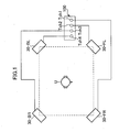
- Fig. 1 shows an outline of using a reverberation imparting apparatus according to an embodiment of the present invention.
- This reverberation imparting apparatus 100 is designed to impart an acoustic effect of a specific acoustic space to sound to be listened to by a user.
- the sound imparted with the acoustic effect is reproduced through four reproduction channels.
- the reverberation imparting apparatus 100 is provided with four reproduction channel terminals Tch1, Tch2, Tch3, and Tch4 connected to speakers 30 (30-FR, 30-FL, 30-BR, and 30-BL), respectively.
- the sound is outputted from these speakers 30 so that a sound field in the specific acoustic space will be reproduced in a listening room where the user or listener is.
- the sound field contains the arrangement of a sound generating point from which the sound is emitted and a sound receiving point at which the sound emitted from the sound generating point is received.
- These speakers 30 are placed in position at almost the same distance from the user U in the listening room.
- the speaker 30-FR is situated to the right in front of the user U (at the lower left in Fig. 1), and the speaker 30-FL is situated to the left in front of the user U (at the lower right in Fig. 1.
- These speakers 30-FR and 30-FL emit sound to reach the user U from the front in the specific acoustic space.
- the speaker 30-BR is situated to the right behind the user U (at the upper left in Fig. 1)
- the speaker 30-BL is situated to the left behind the user U (at the upper right in Fig. 1).
- These speakers 30-BR and 30-BL emit sound to reach the user U from the rear in the specific acoustic space.
- a CPU (Central Processing Unit) 10 is a microprocessor for centralized control of each part of the reverberation imparting apparatus 100.
- the CPU 10 performs computational operations and control of each part according to a program to achieve various functions.
- the CPU 10 is connected through a bus 25 with a ROM (Read Only Memory) 11, a RAM (Random Access Memory) 12, a storage device 13, a display unit 14, an input device 15, an A/D (Analog to Digital) converter 21, and four reproduction processing units 22 (22-1, 22-2, 22-3, and 22-4), respectively.
- the ROM 11 is a nonvolatile memory for storing the program executed by the CPU 10
- the RAM 12 is a nonvolatile memory used as a work area of the CPU 10.
- An analog audio signal to be imparted with an acoustic effect is inputted into the A/D converter 21.
- the audio signal In order to prevent excess reverberant sound from being contained in the sound reproduced, it is desirable that the audio signal be recorded in an anechoic room so that it will contain a musical tone or voice without any reflected sound (a so-called dry source).
- the A/D converter 21 converts the input audio signal to a digital audio signal and outputs the same to the bus 25.
- the audio signal to be imparted with the acoustic effect may be prestored in the storage device 13 as waveform data indicating the waveform of the signal.
- the reverberation imparting apparatus 100 may be provided with a communication device for communication with a server so that the communication device will receive waveform data on an audio signal to be imparted with the acoustic effect.
- the four reproduction processing units 22 correspond to the four reproduction channels and serve as section for imparting different acoustic effects to audio signals, respectively.
- Each of the reproduction processing units 22 includes a convolution operator 221, a DSP (Digital Signal Processor) 222, and a D/A (Digital to Analog) converter 223.
- the convolution operator 221, connected to the bus 25, performs a convolution operation between the impulse response specified by the CPU 10 and the audio signal to be imparted with an acoustic effect.
- the DSP 222 performs various kinds of signal processing, such as signal amplification, such as signal amplification, time delay, and filtering, on a digital signal obtained by the convolution operation performed by the processor 221 at the preceding stage, and outputs the processed signal.
- the D/A converter 223 in each reproduction unit 22 is connected to each corresponding speaker 30.
- the D/A converter 223 in the reproduction unit 22-1 is connected to the speaker 30-FR
- the D/A converter 223 in the reproduction unit 22-2 is connected to the speaker 30-FL.
- the D/A converter 223 in the reproduction unit 22-3 is connected to the speaker 30-BR
- the D/A converter 223 in the reproduction unit 22-4 is connected to the speaker 30-BL.
- Each of these D/A converters 223 converts the digital signal from the preceding DSP 222 to an analog signal and outputs the analog signal to the following speaker 30.
- the storage device 13 stores a program executed by the CPU 10 and various kinds of data used for executing the program.
- a disk drive for writing and reading data to and from a recording medium such as a hard disk or CD-ROM can be adopted as the storage device 13.
- a reverberation imparting program is stored in the storage device 13.
- This reverberation imparting program is to impart an acoustic effect to an audio signal.
- this program is executed by the CPU 10 to implement a function for determining an impulse response corresponding to an acoustic space to be reproduced, a function for instructing the convolution operator 221 on the impulse response determined, and so on.
- the storage device 13 also stores acoustic space data, sound generating point data, and sound receiving point data as data to be used in calculating the impulse response according to the reverberation imparting program.
- the acoustic space data indicates the condition of an acoustic space to be reproduced, and is prepared for each of multiple acoustic spaces such as a concert hall, a church, and a theater.
- One kind of acoustic space data includes space shape information and reflecting characteristics.
- the space shape information indicates the shape of the acoustic space targeted by the acoustic space data, designating the positions of the walls, the ceiling, the floor, etc. as coordinate information in the XYZ orthogonal coordinate system.
- the reflecting characteristics specify the sound reflecting characteristics (sound absorption coefficient, angle of sound reflection, etc.) on the boundary surface such as the walls, the ceiling, and the floor in the acoustic space.
- the sound generating point data is data related to a sound generating point arranged in the acoustic space, and prepared for each of possible objects as sound sources such as a piano, a trumpet, and a clarinet.
- One kind of sound generating point data includes the directional characteristics of the sound generating point.
- the directional characteristic of the sound generating point represents a directivity of the generated sound at the sound generating point. More specifically, the directivity of the generated sound represents an angular distribution of the intensity or magnitude of the sound generated from the sound source.
- the intensity or magnitude of the generated sound normally depends on diverging directions from the sound generating point. The diverging directions may be determined with respect to the orientation of the sound generating point. Typically, the intensity of the generated sound becomes maximal in the diverging or outgoing direction coincident to the orientation of the sound generating point.
- the sound receiving point data is data related to a sound receiving point arranged in the acoustic space. For example, it is prepared for each of possible objects as sound receiving points such as a human being and a microphone.
- One kind of sound receiving point data includes the directional characteristic of the sound receiving point.
- the directional characteristic of the sound receiving point represents a sensitivity of the sound receiving point for the received sound.
- the sensitivity of the sound receiving point varies dependently on converging directions to the sound receiving point with respect to the orientation of the sound receiving point.
- the sensitivity of the microphone may become maximal in the converging or incoming direction coincident to the orientation of the sound receiving point.
- various kinds of acoustic space data, sound generating point data, and sound receiving point data are stored in the storage device 13 so that the user can select from among multiple candidates which kind of acoustic space or musical instrument as a sound generating point he or she desires.
- the storage device 13 needs not necessarily to be built in the reverberation imparting apparatus 100; it may be externally connected to the reverberation imparting apparatus 100. Further, the reverberation imparting apparatus 100 needs not necessarily include the storage device 13.
- the reverberation imparting apparatus 100 may be provided with a device for communication with a networked server so that the acoustic space data, the sound generating point data, and the sound receiving point data will be acquired from the server, respectively.
- the display unit 14 includes a CRT (Cathode Ray Tube) or liquid crystal display panel; it renders various images under the control of the CPU 10.
- the input device 15 is, for example, a keyboard and a mouse, or a joystick; it outputs to the CPU 10 a signal indicating the contents of user's operation.
- the user can operate the input device 15 at his or her discretion to specify an acoustic space to be reproduced, kinds of sound generating point and sound receiving point, and the positions of the sound generating point and the sound receiving point in the acoustic space.
- the user can also operate the input device 15 during reproduction of the acoustic space (that is, while sound is being outputted from the speakers 30) to move the position of the sound generating point or the sound receiving point in the acoustic space at his or her discretion.
- the CPU 10 calculates an impulse response based on not only the condition of the acoustic space corresponding the acoustic space data, but also various other parameters, such as the directional characteristics of the sound generating point indicated by the sound generating point data, the directional characteristics of the sound receiving point indicated by the sound receiving point data, and the positions and directions of the sound generating point and the sound receiving point.
- the CPU 10 determines the direction of a sound generating point based on the position of the sound generating point specified by the user.
- the way of determining the orientation of the sound generating point from its position varies according to the operation mode selected by the user prior to reproduction of the acoustic space.
- three operation modes namely the first to third operation modes, are prepared. Referring to Figs. 3 to 5, a description will be made of how to determine the direction of a sound generating point in each operation mode. Although an actual acoustic space is three-dimensional, the description will be made by taking only the bottom surface into account for convenience in explaining to see the relationship between the acoustic space and the sound generating point or the sound receiving point as a two-dimensional relationship.
- the orientation of the sound generating point is represented as a diagrammatically shown unit vector d.
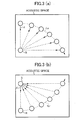
- Figs. 3(a) and 3(b) show the directions of a sound generating point when the first operation mode is selected.
- Fig. 3(a) assumes that a sound generating point S is moved along a dashed line Ls in an acoustic space
- Fig. 3(b) assumes that a sound receiving point R is moved along a dashed line Lr in the acoustic space.
- the orientation of the sound receiving point R as viewed from the sound generating point S is identified as the orientation of the sound generating point S.
- the CPU 10 determines a unit vector di, for example, based on equation (1) shown below, where "i" is a variable representing the point of time when the orientation of the sound generating point S is determined.
- d i r i - s i r i - s i where
- Figs. 4(a) and 4(b) show the directions of the sound generating point when the second operation mode is selected.
- Fig. 4(a) assumes that the sound generating point S is moved along the dashed line Ls in the acoustic space
- Fig. 4(b) assumes that a target point T is moved along a dashed line Lt in the acoustic space.
- the direction of the target point T as viewed from the sound generating point S is identified as the orientation of the sound generating point S.
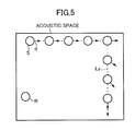
- Fig. 5 shows the orientation of the sound generating point when the third operation mode is selected.
- Fig. 5 assumes that the sound generating point S is moved along the dashed line Ls in the acoustic space.
- the direction of movement of the sound generating point S is identified as the orientation of the sound generating point S.
- the CPU 10 determines the unit vector di, for example, based on equation (3) shown below.
- the coefficient T is a coefficient representing the speed at which the orientation of the sound generating point S gets close to its direction of movement (hereinafter called the "asymptotic rate coefficient").
- the asymptotic rate coefficient T can be set infinitely large so that as the direction of movement of the sound generating point S is changed, the orientation of the sound generating point S becomes the direction of movement after changed.
- d i d i - 1 + ⁇ i • T d i - 1 + ⁇ i • T
- > 0 ⁇ i the rate vector of the sound generating point T : the asymptotic rate coefficient
- Figs. 6, 9 and 12 are flowcharts showing the flow of processing or operations according to the reverberation imparting program.
- a sequence of operations shown in Fig. 6 are performed immediately after the start of the execution of the reverberation imparting program.
- processing shown in Fig. 12 is performed at regular time intervals by a timer interrupt.
- the CPU When starting the reverberation imparting program, the CPU first determines the operation mode selected by the user according to the contents of user's operation of the input device 15 (step Sa1). Then the CPU determines the kind of acoustic space, the kind and position of the sound generating point S, the kind, position, and orientation of the sound receiving point R according to the contents of the user's operation of the input device 15 (step Sa2). When the second operation mode is selected, the CPU 10 determines at step Sa2 the position of the target point T according to the user's operation. It is assumed here that each piece of information is determined according to the instructions from the user, but these pieces of information may be prestored in the storage device 13.
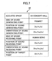
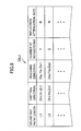
- Fig. 7 shows the specific contents of the recipe file RF.
- the "position of target Point" field is enclosed with a dashed box because it is included in the recipe file RF only when the second operation mode is selected.
- the position of the sound generating point S, and the position and orientation of the sound receiving point R (and further the position of the target point T in the second operation mode) are included in the recipe file RF as coordinate information in the XYZ orthogonal coordinate system.
- the orientation of the sound generating point S is included in the recipe file RF in addition to the parameters determined at step Sa2.
- an initial value corresponding to the operation mode selected at step Sa1 is set.
- the CPU 10 identifies the orientation of the sound receiving point R as viewed from the position of the sound generating point S as an initial value of the orientation of the sound generating point S, and includes it in the recipe file RF.
- the CPU 10 includes the direction of the target point T as viewed from the position of the sound generating point S in the recipe file RF as an initial value of the orientation of the sound generating point S.
- the CPU 10 includes a predetermined direction in the recipe file RF as an initial value of the sound generating point S.
- the CPU 10 reads acoustic space data corresponding to the acoustic space included in the receipt file RF from the storage device 13 (step Sa4).
- the CPU 10 determines a sound ray path, along which sound emitted from the sound generating point S travels until it reaches the sound receiving point R, based on the space shape indicated by the read-out acoustic space data, and the positions of the sound generating point S and the sound receiving point R included in the recipe file RF (step Sa5).
- the sound ray path is determined on the assumption that the emission characteristics of the sound generating point S is independent of the direction from the sound generating point S.
- the sound is emitted in all directions at almost the same level, and among others the paths of sound rays that reach the sound receiving point R after reflected on the wall surfaces and/or the ceiling.
- Various known techniques such as a sound-ray method or mirror image method, can be adopted in determining the sound ray path.
- the CPU 10 creates a sound ray path information table TBL1 as illustrated in Fig. 8 based on each of the sound ray paths determined at step Sa5 (step Sa6).
- the sound ray path information table TBL1 lists multiple records corresponding to the respective sound ray paths determined at step Sa5 in order from the shortest path length to the longest path length.
- a record corresponding to one sound ray path includes the path length of the sound ray path concerned, the emitting direction from the sound generating point S, the direction to reach the sound receiving point R, the number of reflections on the wall surfaces, and a reflection attenuation rate.
- the emitting direction and the reaching direction are represented as vectors in the XYZ orthogonal coordinate system.
- the number of reflections indicates the number of times the sound ray is reflected on the wall surfaces or ceiling in the sound ray path. Further, the reflection attenuation rate denotes the rate of sound attenuation resulting from one or more reflections indicated by the number of reflections.
- the CPU 10 determines an impulse response for each reproduction channel based on the recipe file RF shown in Fig. 7 and the sound ray path information table TBL1 shown in Fig. 8 (step Sa7). After that, the CPU 10 instructs to perform a convolution operation between the impulse response determined at step Sa7 and an audio signal and perform processing for reproducing the audio signal (step Sa8). In other words, the CPU 10 outputs, to the convolution operator 221 of each corresponding reproduction processing unit 22, not only the impulse response determined for each corresponding reproduction channel, but also a command to instruct the convolution operator 221 to perform a convolution operation between the impulse response and the audio signal.
- the command from the CPU 10 triggers the convolution operator 221 of each corresponding reproduction processing unit 22 to perform a convolution operation between the audio signal supplied from the A/D converter 21 and the impulse response received from the CPU 10.
- the audio signal obtained by the convolution operation is subjected to various kinds of signal processing by the DSP 222, and converted to an analog signal at the following D/A converter 223.
- each speaker 30 outputs sound corresponding to the audio signal supplied from the preceding D/A converter 223.
- the CPU 10 divides the frequency band for impulse responses into smaller frequency sub-bands within which the parameters remain substantially constant, and determines an impulse response in each sub-band.
- the frequency band for impulse responses is divided into M sub-bands.
- the CPU 10 first initializes a variable m for specifying a sub-band to "1" (step U1). The CPU then determines a sound ray intensity I of sound that travels along the sound ray path and reaches the sound receiving point R.
- the reference distance r is set according to the size of the acoustic space to be reproduced. Specifically, when the length of the sound ray path is large enough with respect to the size of the acoustic space, the reference distance r is so set as to increase the attenuation rate of the sound that travels along the acoustic ray path.
- the reflection attenuation rate a(fm) is an attenuation rate determined according to the number of sound reflections on the walls or the like in the acoustic space as discussed above. Since the sound reflectance is dependent on the frequency of the sound to be reflected, the reflection attenuation rate a is set on a band basis. Further, the distance attenuation coefficient ⁇ (fm, L) represents an attenuation rate in each band corresponding to the sound travel distance (path length).
- the sounding directivity attenuation coefficient d(fm, X, Y, Z) is an attenuation coefficient determined according to the directional characteristics and orientation of the sound generating point S. Since the directional characteristics of the sound generating point S varies with frequency band of the sound to be emitted, the sounding directivity attenuation coefficient d is dependent on the band fm.
- the CPU 10 reads from the storage device 13 sound generating point data corresponding to the kind of sound generating point S included in the recipe file RF, and corrects the directional characteristics indicated by the sound generating point data according to the orientation of the sound generating point S included in the recipe file RF to determine the sounding directivity attenuation coefficient d(fm, X, Y, Z).
- the sound ray intensity I weighted by the sounding directivity attenuation coefficient d(fm, X, Y, Z) reflects the directional characteristics and orientation of the sound generating point S.
- the CPU 10 determines whether the record processed at step U3 is the last record in the sound ray path information table (step U4). If determining that it is not the last record, the CPU 10 retrieves the next record from the sound ray path information table TBL1 (step U5) and returns to step U3 to determine the sound ray intensity I for an acoustic ray path stored in this record.
- the CPU 10 determines a composite sound ray vector at the sound reception point R (step U6). In other words, the CPU 10 retrieves records of sound ray paths that reach the sound reception point R in the same time period, that is, that have the same sound ray path length, from the sound ray path information table TBL1 to determine the composite sound ray vector from the reaching direction and the sound ray intensity included in each of these records.
- FIG. 10 shows the contents of the composite sound ray table TBL2.
- the composite sound ray table TBL2 contains multiple records corresponding to respective composite sound ray vectors determined at step U6.
- a record corresponding to one composite sound ray vector includes a reverberation delay time, a composite sound ray intensity, and a composite reaching direction.
- the reverberation delay time indicates time required for the sound indicated by the composite sound ray vector to travel from the sound generating point S to the sound receiving point R.
- the composite sound ray intensity indicates the intensity of the composite sound ray vector.
- the composite reaching direction indicates the direction of the composite sound ray to reach the sound receiving point R, and is represented by the direction of the composite sound ray vector.
- the CPU 10 weights the composite sound ray intensity of each composite sound ray vector determined at step U6 with the directional characteristics and orientation of the sound receiving point R. Specifically, the CPU 10 retrieves the first record from the composite sound ray table TBL2 (step U8), multiplies the composite sound ray intensity included in the record by a sound receiving directivity attenuation coefficient g(fm, X, Y, Z), and then writes the results over the corresponding composite sound ray intensity in the composite sound ray table TBL2 (step U9).
- the sound receiving directivity attenuation coefficient g(fm, X, Y, Z) is an attenuation coefficient corresponding to the directional characteristics and orientation of the sound receiving point R.
- the CPU 10 reads from the storage device 13 sound receiving point data corresponding to the kind of sound receiving point R included in the recipe file RF, and corrects the directional characteristics indicated by the sound receiving point data according to the orientation of the sound receiving point R included in the recipe file RF to determine the sound receiving directivity attenuation coefficient g(fm, X, Y, Z).
- the sound ray intensity Ic weighted by the sound receiving directivity attenuation coefficient g(fm, X, Y, Z) reflects the directional characteristics and orientation of the sound receiving point R.
- the CPU 10 determines whether all the records in the composite sound ray table TBL2 have been processed at step U9 (step U10). If determining that any record has not been processed yet, the CPU 102 retrieves the next record (step U11) and returns to step U9 to weight the composite sound ray intensity for this record.
- the CPU 10 performs processing for determining which of four speakers 30 outputs sound corresponding to the composite sound ray vector and assigning the composite sound ray vector to each speaker.
- the CPU 10 first retrieves the first record from the composite sound ray table TBL2 (step U12). The CPU 10 then determines one or more reproduction channels through which the sound corresponding to the composite sound ray vector should be outputted. If determining two or more reproduction channels, then the CPU 10 determines a loudness balance of sounds to be outputted through respective reproduction channels. After that, the CPU 10 adds reproduction channel information representing the determination results to each corresponding record in the composite sound ray table TBL2 (step U13). For example, when the composite reaching direction in the retrieved record indicates arrival from the right front to the sound receiving point R, the sound corresponding to the composite sound ray vector needs to be outputted from the speaker 30-FR situated to the right in front of the listener.
- the CPU 10 adds reproduction channel information indicating the reproduction channel corresponding to the speaker 30-FR (see FIG. 9). Further, when the reaching direction of the composite sound ray vector indicates arrival from the front to the sound receiving point R, the CPU 10 adds reproduction channel information that instructs the speaker 30-FR and the speaker 30-FL to output the sound corresponding to the composite sound ray vector at the same loudness level.
- the CPU 10 determines whether all the records in the composite sound ray table TBL2 have been processed at step U13 (step U14). If determining that any record has not been processed yet, the CPU 10 retrieves the next record (step U15) and returns to step U13 to add reproduction channel information to this record.
- step U13 the CPU 10 increments the variable m by "1" (step U16) and determines whether the variable is greater than the number of divisions M for the frequency band (step U17). If determining that the variable m is equal to or smaller than the number of divisions M, the CPU 10 returns to step U2 to determine an impulse response for the next sub-band.
- the CPU 10 determines an impulse response for each reproduction channel from the composite sound ray intensity Ic determined for each sub-band (step U18).
- the CPU 10 refers to the reproduction channel information added at step U13, and retrieves records for composite sound ray vectors assigned to the same reproduction channel from the composite sound ray table TBL2 created for each sub-band.
- the CPU 102 determines impulse sounds to be listened to at the sound receiving point R on a time-series basis from the reverberation delay time and the composite sound ray intensity of each of the retrieved records.
- the impulse response for each reproduction channel is determined, and used in the convolution operation at step Sa8 in Fig. 6.
- the user can operate the input device 15 at his or her discretion while viewing images (images shown in Figs. 3 to 5) displayed on the display unit 14 to change the position of the sound generating point S or the sound receiving point R, or the position of the target point T when the second operation mode is selected.
- the CPU 10 determines whether the user instructs the movement of each point (step Sb1). If any point is not moved, the impulse response used in a convolution operation does not need changing. In this case, the CPU 10 ends the timer interrupt processing without performing steps Sb2 to Sb7.
- the CPU 10 uses any one of the aforementioned equations (1) to (3) corresponding to the selected operation mode to determine the orientation of the sound generating point P according to the position of the moved point (step Sb2). For example, suppose that the sound generating point P is moved in the first operation mode. In this case, the unit vector di representing the orientation of the sound generating point P after the movement is determined based on the equation (1) from the position vector of the sound generating point S after the movement and the position vector of the sound receiving point R included in the recipe file RF. On the other hand, suppose that the sound receiving point R is moved in the first operation mode.
- the unit vector di representing the orientation of the sound generating point S after the movement is determined based on the equation (1) from the position vector of the sound receiving point R after the movement and the position vector of the sound generating point S included in the recipe file RF.
- the unit vector di representing the direction of a new sound generating point S is determined in the same manner based on the equation (2).
- the CPU 10 determines a rate vector v of the sound generating point S from the position vector of the sound generating point S immediately before the movement, the position vector of the sound generating point S after the movement, and time required between the position vectors. The CPU 10 then determines the unit vector di representing the orientation of the sound generating point P after the movement based on the equation (3) from the rate vector v, the unit vector di-1 representing the orientation of the sound generating point S immediately before the movement, and the predetermined asymptotic rate coefficient T.
- the CPU 10 updates the recipe file RF to replace not only the position of the moved point with the position after the movement, but also the orientation of the sound generating point S with the direction determined at step Sb2 (step Sb3).
- the CPU 10 determines a sound ray path along which sound emitted from the sound generating point S travels until it reaches the sound receiving point R based on the updated recipe file RF (step Sb4).
- the sound ray path is determined in the same manner as in step Sa5 of Fig. 6.
- the CPU 10 creates the sound ray path information table TBL1 according to the sound ray path determined at step Sb4 in the same manner as in step Sa6 of Fig. 6 (step Sb5).
- the CPU 10 creates a new impulse response for each reproduction channel based on the recipe file RF updated at step Sb3 and the sound ray path information table TBL1 crated at the immediately preceding step Sb5 so that the newly created impulse response will reflect the movement of the sound generating point S and the change in direction (step Sb6).
- the procedure for creating the impulse response is the same as mentioned above with reference to Fig. 9.
- the CPU 10 instructs the convolution operator 221 of each reproduction processing unit 22 on the impulse response newly created at step Sb6 (step Sb7).
- sounds outputted from the speakers 30 after completion of this processing are imparted with the acoustic effect that reflects the change in orientation of the sound generating point S.
- the timer interrupt processing described above is repeated at regular time intervals until the user instructs the end of the reproduction of the sound field. Consequently, the movement of each point and a change in orientation of the sound generating point S resulting from the movement are reflected in sound outputted from the speakers 30 whenever necessary in accordance with instructions from the user.
- the orientation of the sound generating point S is automatically determined according to its position (without the need to get instructions from the user). Therefore, the user does not need to specify the orientation of the sound generating point S separately from the position of each point. In other words, the embodiment allows the user to change the orientation of the sound generating point S with a simple operation.
- the embodiment there are prepared three operation modes, each of which determines the orientation of the sound generating point S from the position of the sound generating point S in a different way.
- the first operation mode since the sound generating point S always faces the sound receiving point R, it is possible to reproduce an acoustic space, for example, in which a player playing a musical instrument like a trumpet moves while always pointing the musical instrument at the audience.
- the second operation mode since the sound generating point S always faces the target point T, it is possible to reproduce an acoustic space, for example, in which a player playing a musical instrument moves while always pointing the musical instrument at a specific target.
- the sound generating point S faces its direction of movement, it is possible to reproduce an acoustic space, for example, in which a player playing a musical instrument moves while pointing the musical instrument in its direction of movement (e.g., where the player marches playing the musical instrument).
- a reverberation imparting apparatus will next be described. While the first embodiment illustrates the structure in which the orientation of the sound generating point S is determined according to its position, this embodiment illustrates another structure in which the orientation of the sound receiving point R is determined according to its position.
- components common to those in the reverberation imparting apparatus 100 according to the first embodiment are given the same reference numerals, and the description of the structure and operation common to those in the first embodiment are omitted as needed.
- the orientation of the sound receiving point R is determined so that the sound receiving point R will always face the sound generating point S.
- the orientation of the sound receiving point R is determined so that the sound receiving point R will always face the target point T.
- the orientation of the sound receiving point R is determined so that the sound receiving point R will always face its direction of movement.
- a recipe file RF is so created as to include, in addition to the kind of acoustic space, the kind, position, and orientation of the sound generating point S, and the kind and position of the sound receiving point R determined at step Sa2, an initial value of the orientation of the sound receiving point R according to the operation mode specified at step Sa1.
- the CPU 10 determines whether the user instructs the movement of any one of the sound receiving point R, the sound generating point S, and the target point T.
- the CPU 10 determines the orientation of the sound receiving point R according to the position of each point after the movement and the selected operation mode (step Sb2) and updates the recipe file RF to change the orientation of the sound receiving point R (step Sb3).
- the other operations are the same as those in the first embodiment.
- the position and orientation of the sound receiving point R can be changed with a simple operation.
- the first operation mode since the sound receiving point R faces the sound generating point S regardless of the position of the sound receiving point R, it is possible to reproduce an acoustic space, for example, in which the audience moves facing a player playing a musical instrument.
- the second operation mode since the sound receiving point R always faces the target point T, it is possible to reproduce an acoustic space, for example, in which the audience listening to performance of a musical instrument(s) moves facing a specific target at all times.
- the third operation mode since the sound receiving point R always faces its direction of movement, it is possible to reproduce an acoustic space, for example, in which the audience listening to performance of a musical instrument(s) moves facing its direction of movement.
- the orientation of the sound generating point S in the first embodiment and the orientation of the sound receiving point R in the second embodiment are changed in accordance with instructions from the user, respectively. These embodiments may be combined to change both the directions of the sound generating point S and the sound receiving point R and reflect the changes in the impulse response.
- the first embodiment illustrates the structure in which the sound generating point S faces any one of the directions of the sound receiving point R and the target point T, and the direction of movement of the sound generating point S.
- the sound generating point S may face a direction at a specific angle with respect to one of these directions.
- an angle ⁇ may be determined in accordance with instructions from the user.
- a direction at the angle ⁇ with respect to the direction di determined by one of the aforementioned equations (1) to (3) that is, one of the directions of the sound receiving point R and the target point T, and the direction of movement of the sound generating point S
- the direction di' of the sound generating point S can be determined from the unit vector di determined by one of the aforementioned equations (1) to (3) using the following equation (4):
- an acoustic space in which the sound generating point S moves facing a direction at a certain angle with respect to the orientation of the sound receiving point R or the target point T, or the direction of movement of the sound generating point S.
- the orientation of the sound generating point S is taken into account in this example, the same structure can be adopted in the second embodiment in which the orientation of the sound receiving point R is changed.
- an angle ⁇ is determined in accordance with instructions from the user so that a direction at the angle ⁇ with respect to the orientation of the sound generating point S or the target point T, or the direction of movement of the sound receiving point R will be identified as the orientation of the sound receiving point R.
- the way of determining an impulse response is not limited to those shown in each of the aforementioned embodiments.
- a great number of impulse responses that exhibit different position relations may be measured in actual acoustic spaces beforehand so that an impulse response corresponding to the orientation of the sound generating point S or the sound receiving point R will be selected from among these impulse responses for use in a convolution operation.
- an impulse response is determined in the first embodiment according to the directional characteristics and orientation of the sound generating point S and an impulse response is determined in the second embodiment according to the directional characteristics and orientation of the sound receiving point R.
- the aforementioned embodiments illustrate the structures using four reproduction channels, the number of reproduction channels is not fixed. Further, the aforementioned embodiments use the XYZ orthogonal coordinate system for describing the positions of the sound generating point S, the sound receiving point R, and the target point T, but any other coordinate system may also be used.
- the number of points for the sound generating point S and the sound receiving point R is not limited to one for each point, and acoustic spaces in which two or more sound generating points S or two or more sound receiving points R are arranged may be reproduced.
- the CPU 10 determines a sound ray path for each of the two or more sound generating points S at step Sa5 in Fig. 6 and at step Sb4 in Fig. 12.
- the sound ray path determined is a sound ray path along which sound emitted from the sound generating point S travels until it reaches each corresponding sound receiving point R.
Landscapes
- Physics & Mathematics (AREA)
- Engineering & Computer Science (AREA)
- Acoustics & Sound (AREA)
- Multimedia (AREA)
- Stereophonic System (AREA)
- Reverberation, Karaoke And Other Acoustics (AREA)
- Cable Transmission Systems, Equalization Of Radio And Reduction Of Echo (AREA)
- Measurement Of Velocity Or Position Using Acoustic Or Ultrasonic Waves (AREA)
- Circuit For Audible Band Transducer (AREA)
Abstract
Description
- di:
- the unit vector indicating the orientation of the sound generating point
- si:
- the position vector of the sound generating point
- ri:
- the position vector of the sound receiving point
T : the asymptotic rate coefficient

Claims (18)
- A reverberation apparatus for creating an acoustic effect of an acoustic space which is arranged under an instruction of a user with a sound generating point for generating a sound and a sound receiving point for receiving the sound which travels from the sound generating point to the sound receiving point through sound ray paths within the acoustic space, and for applying the created acoustic effect to an audio signal representative of the sound, the reverberation apparatus comprising:a storage section that stores a directional characteristic representing a directivity of the generated sound at the sound generating point;a position determining section that determines a position of the sound generating point within the acoustic space on the basis of the instruction from the user;an orientation determining section that determines an orientation of the sound generating point based on the position determined by the position determining section;an impulse response determining section that determines an impulse response for each of the sound ray paths along which the sound emitted from the sound generating point travels to reach the sound receiving point, in accordance with the directional characteristic of the generated sound stored in the storage section and the orientation of the sound generating point determined by the orientation determining section; anda calculation section that performs a convolution operation between the impulse response determined by the impulse response determining section and the audio signal so as to apply thereto the acoustic effect.
- The reverberation apparatus according to claim 1, wherein the orientation determining section identifies a direction to a given target point from the sound generating point at the position determined by the position determining section, and determines the orientation of the sound generating point in terms of the identified direction from the sound generating point to the target point.
- The reverberation apparatus according to claim 2, wherein the orientation determining section sets the target point to the sound receiving point in accordance with the instruction by the user.
- The reverberation apparatus according to claim 1, wherein the orientation determining section identifies a first direction to a given target point from the sound generating point at the position determined by the position determining section, and determines the orientation of the sound generating point in terms of a second direction making a predetermined angle with respect to the identified first direction.
- The reverberation apparatus according to claim 4, wherein the orientation determining section sets the target point to the sound receiving point in accordance with the instruction by the user.
- The reverberation apparatus according to claim 1, wherein the position determining section determines the position of the sound generating point which moves in accordance with the instruction from the user, and wherein the orientation determining section identifies based on the determined position of the sound generating point a progressing direction along which the sound generating point moves, and determines the orientation of the sound generating point in terms of the identified progressing direction.
- The reverberation apparatus according to claim 1, wherein the position determining section determines the position of the sound generating point which moves in accordance with the instruction from the user, and wherein the orientation determining section identifies based on the determined position of the sound generating point a progressing direction along which the sound generating point moves, and determines the orientation of the sound generating point in terms of an angular direction making a predetermined angle with respect to the identified progressing direction.
- A reverberation apparatus for creating an acoustic effect of an acoustic space which is arranged under an instruction of a user with a sound generating point for generating a sound and a sound receiving point for receiving the sound which travels from the sound generating point to the sound receiving point through sound ray paths within the acoustic space, and for applying the created acoustic effect to an audio signal representative of the sound, the reverberation apparatus comprising:a storage section that stores a directional characteristic of a sensitivity of the sound receiving point for the received sound;a position determining section that determines a position of the sound receiving point within the acoustic space on the basis of the instruction from the user;an orientation determining section that determines an orientation of the sound receiving point based on the position determined by the position determining section;an impulse response determining section that determines an impulse response for each of the sound ray paths along which the sound emitted from the sound generating point travels to reach the sound receiving point, in accordance with the directional characteristic of the sensitivity for the received sound stored in the storage section and the orientation of the sound receiving point determined by the orientation determining section; anda calculation section that performs a convolution operation between the impulse response determined by the impulse response determining section and the audio signal so as to apply thereto the acoustic effect.
- The reverberation apparatus according to claim 8, wherein the orientation determining section identifies a direction to a given target point from the sound receiving point at the position determined by the position determining section, and determines the orientation of the sound receiving point in terms of the identified direction from the sound receiving point to the target point.
- The reverberation apparatus according to claim 9, wherein the orientation determining section sets the target point to the sound generating point in accordance with the instruction by the user.
- The reverberation apparatus according to claim 8, wherein the orientation determining section identifies a first direction to a given target point from the sound receiving point at the position determined by the position determining section, and determines the orientation of the sound receiving point in terms of a second direction making a predetermined angle with respect to the identified first direction.
- The reverberation apparatus according to claim 11, wherein the orientation determining section sets the target point to the sound generating point in accordance with the instruction by the user.
- The reverberation apparatus according to claim 8, wherein the position determining section determines the position of the sound receiving point which moves in accordance with the instruction from the user, and wherein the orientation determining section identifies based on the determined position of the sound receiving point a progressing direction along which the sound receiving point moves, and determines the orientation of the sound receiving point in terms of the identified progressing direction.
- The reverberation apparatus according to claim 8, wherein the position determining section determines the position of the sound receiving point which moves in accordance with the instruction from the user, and wherein the orientation determining section identifies based on the determined position of the sound receiving point a progressing direction along which the sound receiving point moves, and determines the orientation of the sound receiving point in terms of an angular direction making a predetermined angle with respect to the identified progressing direction.
- A reverberation program executable by a computer for creating an acoustic effect of an acoustic space which is arranged under an instruction of a user with a sound generating point for generating a sound and a sound receiving point for receiving the sound which travels from the sound generating point to the sound receiving point through sound ray paths within the acoustic space, and for applying the created acoustic effect to an audio signal representative of the sound, the reverberation program comprising the steps of:providing a directional characteristic representing a directivity of the generated sound at the sound generating point;determining a position of the sound generating point within the acoustic space on the basis of the instruction from the user;determining an orientation of the sound generating point based on the determined position thereof;determining an impulse response for each of the sound ray paths along which the sound emitted from the sound generating point travels to reach the sound receiving point, in accordance with the provided directional characteristic of the generated sound and the determined orientation of the sound generating point; andperforming a convolution operation between the determined impulse response and the audio signal so as to apply thereto the acoustic effect.
- A reverberation program executable by a computer for creating an acoustic effect of an acoustic space which is arranged under an instruction of a user with a sound generating point for generating a sound and a sound receiving point for receiving the sound which travels from the sound generating point to the sound receiving point through sound ray paths within the acoustic space, and for applying the created acoustic effect to an audio signal representative of the sound, the reverberation program comprising the steps of:providing a directional characteristic of a sensitivity of the sound receiving point for the received sound;determining a position of the sound receiving point within the acoustic space on the basis of the instruction from the user;determining an orientation of the sound receiving point based on the determined position thereof;determining an impulse response for each of the sound ray paths along which the sound emitted from the sound generating point travels to reach the sound receiving point, in accordance with the provided directional characteristic of the sensitivity for the received sound and the determined orientation of the sound receiving point; andperforming a convolution operation between the determined impulse response and the audio signal so as to apply thereto the acoustic effect.
- A reverberation method of creating an acoustic effect for an acoustic space which is arranged under an instruction of a user with a sound generating point for generating a sound and a sound receiving point for receiving the sound which travels from the sound generating point to the sound receiving point through sound ray paths within the acoustic space, and applying the created acoustic effect to an audio signal representative of the sound, the reverberation method comprising the steps of:providing a directional characteristic representing a directivity of the generated sound at the sound generating point;determining a position of the sound generating point within the acoustic space on the basis of the instruction from the user;determining an orientation of the sound generating point based on the determined position thereof;determining an impulse response for each of the sound ray paths along which the sound emitted from the sound generating point travels to reach the sound receiving point, in accordance with the provided directional characteristic of the generated sound and the determined orientation of the sound generating point; andperforming a convolution operation between the determined impulse response and the audio signal so as to apply thereto the acoustic effect.
- A reverberation method of creating an acoustic effect for an acoustic space which is arranged under an instruction of a user with a sound generating point for generating a sound and a sound receiving point for receiving the sound which travels from the sound generating point to the sound receiving point through sound ray paths within the acoustic space, and applying the created acoustic effect to an audio signal representative of the sound, the reverberation method comprising the steps of:providing a directional characteristic of a sensitivity of the sound receiving point for the received sound;determining a position of the sound receiving point within the acoustic space on the basis of the instruction from the user;determining an orientation of the sound receiving point based on the determined position thereof;determining an impulse response for each of the sound ray paths along which the sound emitted from the sound generating point travels to reach the sound receiving point, in accordance with the provided directional characteristic of the sensitivity for the received sound and the determined orientation of the sound receiving point; andperforming a convolution operation between the determined impulse response and the audio signal so as to apply thereto the acoustic effect.
Applications Claiming Priority (2)
| Application Number | Priority Date | Filing Date | Title |
|---|---|---|---|
| JP2003099565A JP4464064B2 (en) | 2003-04-02 | 2003-04-02 | Reverberation imparting device and reverberation imparting program |
| JP2003099565 | 2003-04-02 |
Publications (2)
| Publication Number | Publication Date |
|---|---|
| EP1465152A2 true EP1465152A2 (en) | 2004-10-06 |
| EP1465152A3 EP1465152A3 (en) | 2008-06-25 |
Family
ID=32844693
Family Applications (1)
| Application Number | Title | Priority Date | Filing Date |
|---|---|---|---|
| EP04101234A Withdrawn EP1465152A3 (en) | 2003-04-02 | 2004-03-25 | Reverberation apparatus controllable by positional information of sound source |
Country Status (3)
| Country | Link |
|---|---|
| US (1) | US7751574B2 (en) |
| EP (1) | EP1465152A3 (en) |
| JP (1) | JP4464064B2 (en) |
Cited By (2)
| Publication number | Priority date | Publication date | Assignee | Title |
|---|---|---|---|---|
| WO2014173069A1 (en) * | 2013-04-23 | 2014-10-30 | 华为技术有限公司 | Sound effect adjusting method, apparatus, and device |
| WO2023003482A1 (en) * | 2021-07-21 | 2023-01-26 | Wojdyllo Piotr | Method of sound processing simulating the acoustics of ancient theatre |
Families Citing this family (9)
| Publication number | Priority date | Publication date | Assignee | Title |
|---|---|---|---|---|
| US7859533B2 (en) | 2005-04-05 | 2010-12-28 | Yamaha Corporation | Data processing apparatus and parameter generating apparatus applied to surround system |
| JP4721097B2 (en) * | 2005-04-05 | 2011-07-13 | ヤマハ株式会社 | Data processing method, data processing apparatus, and program |
| DE102005043641A1 (en) * | 2005-05-04 | 2006-11-09 | Fraunhofer-Gesellschaft zur Förderung der angewandten Forschung e.V. | Apparatus and method for generating and processing sound effects in spatial sound reproduction systems by means of a graphical user interface |
| US9037468B2 (en) * | 2008-10-27 | 2015-05-19 | Sony Computer Entertainment Inc. | Sound localization for user in motion |
| JP5456622B2 (en) * | 2010-08-31 | 2014-04-02 | 株式会社スクウェア・エニックス | Video game processing apparatus and video game processing program |
| US10057706B2 (en) * | 2014-11-26 | 2018-08-21 | Sony Interactive Entertainment Inc. | Information processing device, information processing system, control method, and program |
| US10856098B1 (en) * | 2019-05-21 | 2020-12-01 | Facebook Technologies, Llc | Determination of an acoustic filter for incorporating local effects of room modes |
| KR102790646B1 (en) * | 2019-06-21 | 2025-04-04 | 소니그룹주식회사 | Signal processing device and method, and program stored on a computer-readable recording medium |
| KR102363969B1 (en) * | 2020-04-29 | 2022-02-17 | 국방과학연구소 | Method for simulating underwater sound transmission channel based on eigenray tracing |
Family Cites Families (7)
| Publication number | Priority date | Publication date | Assignee | Title |
|---|---|---|---|---|
| JP3368912B2 (en) | 1992-01-08 | 2003-01-20 | ヤマハ株式会社 | Musical tone waveform signal generating apparatus and musical tone waveform signal processing method |
| EP0593228B1 (en) * | 1992-10-13 | 2000-01-05 | Matsushita Electric Industrial Co., Ltd. | Sound environment simulator and a method of analyzing a sound space |
| US6188769B1 (en) | 1998-11-13 | 2001-02-13 | Creative Technology Ltd. | Environmental reverberation processor |
| JP2000197198A (en) | 1998-12-25 | 2000-07-14 | Matsushita Electric Ind Co Ltd | Sound image moving device |
| JP3584800B2 (en) | 1999-08-17 | 2004-11-04 | ヤマハ株式会社 | Sound field reproduction method and apparatus |
| JP2001251698A (en) | 2000-03-07 | 2001-09-14 | Canon Inc | Sound processing system, control method thereof, and storage medium |
| JP4062959B2 (en) | 2002-04-26 | 2008-03-19 | ヤマハ株式会社 | Reverberation imparting device, reverberation imparting method, impulse response generating device, impulse response generating method, reverberation imparting program, impulse response generating program, and recording medium |
-
2003
- 2003-04-02 JP JP2003099565A patent/JP4464064B2/en not_active Expired - Fee Related
-
2004
- 2004-03-23 US US10/808,030 patent/US7751574B2/en not_active Expired - Fee Related
- 2004-03-25 EP EP04101234A patent/EP1465152A3/en not_active Withdrawn
Cited By (2)
| Publication number | Priority date | Publication date | Assignee | Title |
|---|---|---|---|---|
| WO2014173069A1 (en) * | 2013-04-23 | 2014-10-30 | 华为技术有限公司 | Sound effect adjusting method, apparatus, and device |
| WO2023003482A1 (en) * | 2021-07-21 | 2023-01-26 | Wojdyllo Piotr | Method of sound processing simulating the acoustics of ancient theatre |
Also Published As
| Publication number | Publication date |
|---|---|
| JP4464064B2 (en) | 2010-05-19 |
| US20040196983A1 (en) | 2004-10-07 |
| US7751574B2 (en) | 2010-07-06 |
| EP1465152A3 (en) | 2008-06-25 |
| JP2004312109A (en) | 2004-11-04 |
Similar Documents
| Publication | Publication Date | Title |
|---|---|---|
| JP7367785B2 (en) | Audio processing device and method, and program | |
| JP4062959B2 (en) | Reverberation imparting device, reverberation imparting method, impulse response generating device, impulse response generating method, reverberation imparting program, impulse response generating program, and recording medium | |
| JP4674505B2 (en) | Audio signal processing method, sound field reproduction system | |
| US5784467A (en) | Method and apparatus for reproducing three-dimensional virtual space sound | |
| US5452360A (en) | Sound field control device and method for controlling a sound field | |
| US20060000343A1 (en) | Method for making electronic tones close to acoustic tones, recording system | |
| JP4573433B2 (en) | Method and system for processing directional sound in a virtual acoustic environment | |
| JP2007266967A (en) | Sound image localizer and multichannel audio reproduction device | |
| JP2001125578A (en) | Method and device for reproducing sound field | |
| US12342151B2 (en) | Live data distribution method, live data distribution system, and live data distribution apparatus | |
| US7751574B2 (en) | Reverberation apparatus controllable by positional information of sound source | |
| JP2003061200A (en) | Voice processing device, voice processing method, and control program | |
| JP3823847B2 (en) | SOUND CONTROL DEVICE, SOUND CONTROL METHOD, PROGRAM, AND RECORDING MEDIUM | |
| US20240163624A1 (en) | Information processing device, information processing method, and program | |
| US7572970B2 (en) | Digital piano apparatus, method for synthesis of sound fields for digital piano, and computer-readable storage medium | |
| WO2022113393A1 (en) | Live data delivery method, live data delivery system, live data delivery device, live data reproduction device, and live data reproduction method | |
| JP4883197B2 (en) | Audio signal processing method, sound field reproduction system | |
| CN115119101A (en) | Sound signal processing method, sound signal processing device, and recording medium | |
| CN113766394B (en) | Sound signal processing method, sound signal processing device, and sound signal processing program | |
| EP3719789B1 (en) | Sound signal processor and sound signal processing method | |
| JPH06335096A (en) | Sound field reproducing device | |
| JP2021131433A (en) | Sound signal processing method and sound signal processing device | |
| JP3671756B2 (en) | Sound field playback device | |
| JP3368912B2 (en) | Musical tone waveform signal generating apparatus and musical tone waveform signal processing method | |
| WO2023162581A1 (en) | Sound production device, sound production method, and sound production program |
Legal Events
| Date | Code | Title | Description |
|---|---|---|---|
| PUAI | Public reference made under article 153(3) epc to a published international application that has entered the european phase |
Free format text: ORIGINAL CODE: 0009012 |
|
| 17P | Request for examination filed |
Effective date: 20040329 |
|
| AK | Designated contracting states |
Kind code of ref document: A2 Designated state(s): AT BE BG CH CY CZ DE DK EE ES FI FR GB GR HU IE IT LI LU MC NL PL PT RO SE SI SK TR |
|
| AX | Request for extension of the european patent |
Extension state: AL LT LV MK |
|
| RAP1 | Party data changed (applicant data changed or rights of an application transferred) |
Owner name: YAMAHA CORPORATION |
|
| PUAL | Search report despatched |
Free format text: ORIGINAL CODE: 0009013 |
|
| AK | Designated contracting states |
Kind code of ref document: A3 Designated state(s): AT BE BG CH CY CZ DE DK EE ES FI FR GB GR HU IE IT LI LU MC NL PL PT RO SE SI SK TR |
|
| AX | Request for extension of the european patent |
Extension state: AL LT LV MK |
|
| AKX | Designation fees paid |
Designated state(s): DE GB |
|
| 17Q | First examination report despatched |
Effective date: 20111214 |
|
| STAA | Information on the status of an ep patent application or granted ep patent |
Free format text: STATUS: THE APPLICATION IS DEEMED TO BE WITHDRAWN |
|
| 18D | Application deemed to be withdrawn |
Effective date: 20171003 |