EP1464979A1 - Coil structure for magnetic resonance imaging - Google Patents
Coil structure for magnetic resonance imaging Download PDFInfo
- Publication number
- EP1464979A1 EP1464979A1 EP04251804A EP04251804A EP1464979A1 EP 1464979 A1 EP1464979 A1 EP 1464979A1 EP 04251804 A EP04251804 A EP 04251804A EP 04251804 A EP04251804 A EP 04251804A EP 1464979 A1 EP1464979 A1 EP 1464979A1
- Authority
- EP
- European Patent Office
- Prior art keywords
- coil
- turns
- layers
- layer
- self
- Prior art date
- Legal status (The legal status is an assumption and is not a legal conclusion. Google has not performed a legal analysis and makes no representation as to the accuracy of the status listed.)
- Granted
Links
- 239000011810 insulating material Substances 0.000 claims abstract description 9
- 239000004744 fabric Substances 0.000 claims description 3
- 239000011521 glass Substances 0.000 claims description 3
- 230000000694 effects Effects 0.000 abstract description 10
- 238000002595 magnetic resonance imaging Methods 0.000 abstract description 3
- 238000004611 spectroscopical analysis Methods 0.000 abstract description 3
- 238000004804 winding Methods 0.000 description 8
- 238000009413 insulation Methods 0.000 description 6
- 230000015556 catabolic process Effects 0.000 description 5
- 238000000034 method Methods 0.000 description 5
- 230000000712 assembly Effects 0.000 description 1
- 238000000429 assembly Methods 0.000 description 1
- 238000006731 degradation reaction Methods 0.000 description 1
- 238000003384 imaging method Methods 0.000 description 1
- 238000005259 measurement Methods 0.000 description 1
Images

Classifications
-
- H—ELECTRICITY
- H01—ELECTRIC ELEMENTS
- H01F—MAGNETS; INDUCTANCES; TRANSFORMERS; SELECTION OF MATERIALS FOR THEIR MAGNETIC PROPERTIES
- H01F27/00—Details of transformers or inductances, in general
- H01F27/28—Coils; Windings; Conductive connections
- H01F27/32—Insulating of coils, windings, or parts thereof
- H01F27/323—Insulation between winding turns, between winding layers
-
- G—PHYSICS
- G01—MEASURING; TESTING
- G01R—MEASURING ELECTRIC VARIABLES; MEASURING MAGNETIC VARIABLES
- G01R33/00—Arrangements or instruments for measuring magnetic variables
- G01R33/20—Arrangements or instruments for measuring magnetic variables involving magnetic resonance
- G01R33/28—Details of apparatus provided for in groups G01R33/44 - G01R33/64
- G01R33/38—Systems for generation, homogenisation or stabilisation of the main or gradient magnetic field
- G01R33/387—Compensation of inhomogeneities
- G01R33/3875—Compensation of inhomogeneities using correction coil assemblies, e.g. active shimming
-
- H—ELECTRICITY
- H01—ELECTRIC ELEMENTS
- H01F—MAGNETS; INDUCTANCES; TRANSFORMERS; SELECTION OF MATERIALS FOR THEIR MAGNETIC PROPERTIES
- H01F5/00—Coils
-
- H—ELECTRICITY
- H01—ELECTRIC ELEMENTS
- H01F—MAGNETS; INDUCTANCES; TRANSFORMERS; SELECTION OF MATERIALS FOR THEIR MAGNETIC PROPERTIES
- H01F5/00—Coils
- H01F5/06—Insulation of windings
Definitions
- This invention relates to magnetic coil structures for use in magnetic resonance imaging and spectroscopy (MRIS).
- MRIS magnetic resonance imaging and spectroscopy
- Magnetic resonance imaging and spectroscopy (MRIS) systems generally comprise a plurality of cylindrical concentric coils which are located around a region within which a patient can be located.
- the coils include an outermost DC coil which is used to provide a strong constant magnetic field, an inner radio frequency (RF) coil arrangement which is arranged concentrically within the DC coil and a gradient coil assembly which is located between the RF coil and the outer DC coil.
- the gradient coil assembly is arranged to generate a time-varying audio frequency magnetic field which causes the response frequency of the nuclei of the patient to depend upon their positions within the field.
- the coils which generate the strong constant magnetic field are generally super-conducting coils.
- a known method of counter-acting this effect is by providing multi-turn electrical windings known as shim coils and driving DC electrical currents through those windings.
- a typical high performance MRIS system may contain 8 to 12 shim coils, each of which is arranged to correct an inhomogeneity with a particular spatial form.
- the shim coils can also be used to correct intrinsic inhomogeneities of the super-conductive magnet itself.
- the gradient sequence contains a range of frequencies from zero to 10 kHz or more and this is often referred to as "audio frequency”.
- a further problem with such arrangements is that changing currents in a gradient coil may induce voltages in the shim coil that are large enough to cause insulation between shim coils in adjacent layers to break down leading to failure of the entire coil.
- Self resonance means that currents are flowing in sub-sections of the windings of a coil coupled by internal capacitance. Such currents may be induced even though the coil, as a whole, does not have the correct symmetry to interact with the gradient coil. Furthermore, such currents may be induced even though the coil itself is open circuit.
- the present invention is concerned with techniques for overcoming or alleviating this problem.
- an electrical coil which is wound so that there are a plurality of layers with each layer having a plurality of turns, wherein an insulating material is disposed between the turns of each layer.
- the insulating material reduces the capacitance between the turns and this has the effect of increasing the self-resonant frequency of the coil.
- the self-resonant frequency of that coil may be raised to a value beyond the band width of the amplifier associated with the gradient coils. This consequently has the effect of reducing the problem of self-resonance. It also improves the insulation between layers, reducing the likelihood of insulation breakdown between adjacent shim coil layers.
- an electrical coil which comprises a plurality of layers each with n turns wherein the coil is wound so as to comprise two or more portions each of which has layers which contain fewer than n turns.
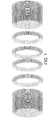
- Figure 1 shows schematically how shim coils are particularly arranged into packs or blocks for use in MRIS systems.
- currents can flow in sub-sections of the windings of such coils coupled by internal capacitance and this is illustrated in Figure 2A of the drawings which shows the inter-turn connections.
- Figure 2A of the drawings shows the inter-turn connections.
- This Figure shows three layers 10, 11, 12 each having a number of turns 15.
- the illustrated inter-turn connections have the effect of producing so-called self-resonance which can affect the performance of the MRIS system.
- Figure 2B illustrates a first embodiment of the present invention for reducing or alleviating this self-resonant effect.
- this first embodiment there are illustrated three layers 10, 11 and 12 of windings each having a number of turns 15.
- the coil has been formed in such a way that each layer of turns is separated from the next layer by a layer of insulating material 16.
- the layer of insulating material may for example, be a layer of glass cloth having a thickness of 0.2 mm.
- the presence of the layer 16 has the effect of increasing the self-resonant frequency of the coil.
- windings will typically be made from rectangular section lacquered wire and be very closely packed as shown in Figure 2.
- a layer of glass cloth 16 0.2mm thick has the effect of increasing the self-resonant frequency from 14.75kHz to 23.0kHz taking it outside the typical bandwidth of the amplifier of the gradient coils.
- FIG. 2C of the drawings A second embodiment of the present invention is illustrated in Figure 2C of the drawings.
- a pack such as that shown in Figure 2A of the drawings which has five layers with 27 turns per layer can have up to 54 turns connected in series between physically adjacent turns in adjacent layers. This means that substantial internal voltages can build up inside the coil and this leads to high capacitive stored energy and the possibility of insulation breakdown.
- the principle illustrated in Figure 2C is to divide the coil into multiple portions (20, 21) so that, for example, for the specific coil referred to above, there is one portion having 13 turns in five layers and another portion having 14 turns in five layers.
- the coil can be divided into as many portions as are deemed necessary to provide the appropriate increase in self-resonant frequency.
- the technique of forming the coil in portions can be used in conjunction with the technique of using insulating material between the layers in the manner illustrated in Figure 2C.
- the self-resonant frequency can be increased to 46 kHz. It will be appreciated that further increases in resonant frequency can be achieved by sub-dividing the coil into more portions than those illustrated in Figure 2C.
Landscapes
- Engineering & Computer Science (AREA)
- Power Engineering (AREA)
- Physics & Mathematics (AREA)
- Condensed Matter Physics & Semiconductors (AREA)
- General Physics & Mathematics (AREA)
- Magnetic Resonance Imaging Apparatus (AREA)
Abstract
Description
- This invention relates to magnetic coil structures for use in magnetic resonance imaging and spectroscopy (MRIS).
- Magnetic resonance imaging and spectroscopy (MRIS) systems generally comprise a plurality of cylindrical concentric coils which are located around a region within which a patient can be located. The coils include an outermost DC coil which is used to provide a strong constant magnetic field, an inner radio frequency (RF) coil arrangement which is arranged concentrically within the DC coil and a gradient coil assembly which is located between the RF coil and the outer DC coil. The gradient coil assembly is arranged to generate a time-varying audio frequency magnetic field which causes the response frequency of the nuclei of the patient to depend upon their positions within the field. The coils which generate the strong constant magnetic field are generally super-conducting coils. The presence of a patient in the magnetic field may distort the main magnetic field making it insufficiently uniform for imaging or spectroscopic measurements. A known method of counter-acting this effect is by providing multi-turn electrical windings known as shim coils and driving DC electrical currents through those windings. A typical high performance MRIS system may contain 8 to 12 shim coils, each of which is arranged to correct an inhomogeneity with a particular spatial form. The shim coils can also be used to correct intrinsic inhomogeneities of the super-conductive magnet itself.
- It is common practice to incorporate shim coils within the structure of the actively shielded gradient coil assemblies which are switched rapidly on and off in a precisely timed sequence to generate MR images. The gradient sequence contains a range of frequencies from zero to 10 kHz or more and this is often referred to as "audio frequency".
- As MRIS systems have developed they have operated at higher and higher magnetic fields, eg 3T and above. As a consequence, the field strengths required from the shim coils increase proportionately resulting in coils with ever increasing numbers of turns. It is often necessary to use packs of multilayered windings to obtain the required field strength (see Figure 1). A problem with such arrangements is that the packs become what is known as self-resonant at relatively low frequencies, eg below 20 kHz. In some cases the resonance may couple to a nearby gradient coil and its amplifier causing them to become unstable. This can disrupt the precise timing of the gradient sequence with a consequent degradation of the performance of the MRIS system.
- A further problem with such arrangements is that changing currents in a gradient coil may induce voltages in the shim coil that are large enough to cause insulation between shim coils in adjacent layers to break down leading to failure of the entire coil.
- Self resonance means that currents are flowing in sub-sections of the windings of a coil coupled by internal capacitance. Such currents may be induced even though the coil, as a whole, does not have the correct symmetry to interact with the gradient coil. Furthermore, such currents may be induced even though the coil itself is open circuit.
- The present invention is concerned with techniques for overcoming or alleviating this problem.
- According to a first aspect of the present invention, there is provided an electrical coil which is wound so that there are a plurality of layers with each layer having a plurality of turns, wherein an insulating material is disposed between the turns of each layer. The insulating material reduces the capacitance between the turns and this has the effect of increasing the self-resonant frequency of the coil. Thus, in the case of a shim coil for use in MRIS, the self-resonant frequency of that coil may be raised to a value beyond the band width of the amplifier associated with the gradient coils. This consequently has the effect of reducing the problem of self-resonance. It also improves the insulation between layers, reducing the likelihood of insulation breakdown between adjacent shim coil layers.
- According to another aspect of the present invention there is provided an electrical coil which comprises a plurality of layers each with n turns wherein the coil is wound so as to comprise two or more portions each of which has layers which contain fewer than n turns. By forming the coil in portions in this way inter-turn voltages are reduced and in the case of a shim coil this has the effect of increasing the self-resonant frequency and further reducing the likelihood of insulation breakdown between adjacent shim coil layers. If such a coil is formed with the insulating feature of the first aspect the self-resonant frequency can be increased still further.
- The invention will be described now by way of example only with particular reference to the accompanying drawings.
- In the drawings:
- Figure 1 is a schematic view illustrating a typical arrangement of shim coils used in MRIS.
- Figure 2A is a cross-section through a single block of such shim coil.
- Figure 2B is a cross-section illustrating one embodiment in accordance with the present invention; and
- Figure 2C is a cross-section illustrating another embodiment in accordance with the present invention.
-
- Figure 1 shows schematically how shim coils are particularly arranged into packs or blocks for use in MRIS systems. As has been explained, currents can flow in sub-sections of the windings of such coils coupled by internal capacitance and this is illustrated in Figure 2A of the drawings which shows the inter-turn connections. This Figure shows three
layers turns 15. The illustrated inter-turn connections have the effect of producing so-called self-resonance which can affect the performance of the MRIS system. - Figure 2B illustrates a first embodiment of the present invention for reducing or alleviating this self-resonant effect. In this first embodiment there are illustrated three
layers turns 15. The coil has been formed in such a way that each layer of turns is separated from the next layer by a layer ofinsulating material 16. The layer of insulating material may for example, be a layer of glass cloth having a thickness of 0.2 mm. The presence of thelayer 16 has the effect of increasing the self-resonant frequency of the coil. - Considering as an example a multi-layer pack of windings having five layers with 27 turns per layer, this gives 135 turns in total. For minimum resistance, the windings will typically be made from rectangular section lacquered wire and be very closely packed as shown in Figure 2.
- For such an example, a layer of
glass cloth 16 0.2mm thick has the effect of increasing the self-resonant frequency from 14.75kHz to 23.0kHz taking it outside the typical bandwidth of the amplifier of the gradient coils. - A second embodiment of the present invention is illustrated in Figure 2C of the drawings. A pack such as that shown in Figure 2A of the drawings which has five layers with 27 turns per layer can have up to 54 turns connected in series between physically adjacent turns in adjacent layers. This means that substantial internal voltages can build up inside the coil and this leads to high capacitive stored energy and the possibility of insulation breakdown.
- This effect is reduced by structuring the coil as shown in Figure 2C of the drawings. The principle illustrated in Figure 2C is to divide the coil into multiple portions (20, 21) so that, for example, for the specific coil referred to above, there is one portion having 13 turns in five layers and another portion having 14 turns in five layers. This means that the internal voltages referred to above are significantly reduced and again, this has the consequence of increasing the self-resonant frequency and reducing the likelihood of insulation breakdown. The coil can be divided into as many portions as are deemed necessary to provide the appropriate increase in self-resonant frequency. Advantageously, the technique of forming the coil in portions can be used in conjunction with the technique of using insulating material between the layers in the manner illustrated in Figure 2C. For the example of the coil given above, the self-resonant frequency can be increased to 46 kHz. It will be appreciated that further increases in resonant frequency can be achieved by sub-dividing the coil into more portions than those illustrated in Figure 2C.
- The techniques for increasing the self-resonant frequency have been described above in relation to axial shim coils. It will be appreciated that they are applicable equally to other coil types such as transverse shim coils.
Claims (5)
- An electrical coil which is wound so that there are a plurality of layers with each layer having a plurality of turns, wherein an insulating material is disposed between the turns of each layer.
- An electrical coil according to claim 1 wherein the insulating material is glass cloth.
- An electrical coil which comprises a plurality of layers each with n turns wherein the coil is wound so as to comprise two or more portions each of which has layers which contain fewer than n turns.
- An electrical coil according to claim 4 wherein insulating material is disposed between the turns of each layer.
- An electrical coil according to any one of claims 1 or claim 4 wherein the coil is a shim coil for an MRIS apparatus.
Applications Claiming Priority (2)
| Application Number | Priority Date | Filing Date | Title |
|---|---|---|---|
| GBGB0307728.6A GB0307728D0 (en) | 2003-04-03 | 2003-04-03 | Coil structure for magnetic resonance imaging |
| GB0307728 | 2003-04-03 |
Publications (2)
| Publication Number | Publication Date |
|---|---|
| EP1464979A1 true EP1464979A1 (en) | 2004-10-06 |
| EP1464979B1 EP1464979B1 (en) | 2016-07-27 |
Family
ID=9956131
Family Applications (1)
| Application Number | Title | Priority Date | Filing Date |
|---|---|---|---|
| EP04251804.3A Expired - Lifetime EP1464979B1 (en) | 2003-04-03 | 2004-03-26 | Coil structure for magnetic resonance imaging |
Country Status (6)
| Country | Link |
|---|---|
| US (1) | US7075397B2 (en) |
| EP (1) | EP1464979B1 (en) |
| JP (1) | JP4837898B2 (en) |
| CN (1) | CN100359611C (en) |
| ES (1) | ES2596278T3 (en) |
| GB (1) | GB0307728D0 (en) |
Cited By (1)
| Publication number | Priority date | Publication date | Assignee | Title |
|---|---|---|---|---|
| US10543217B2 (en) | 2009-08-24 | 2020-01-28 | Organext Research B.V. | Method of treating frailty |
Citations (5)
| Publication number | Priority date | Publication date | Assignee | Title |
|---|---|---|---|---|
| GB1003254A (en) * | 1961-03-09 | 1965-09-02 | Blaupunkt Werke Gmbh | Improvements in or relating to line output transformers for television apparatus |
| JPS5679418A (en) * | 1979-11-30 | 1981-06-30 | Aichi Electric Mfg Co Ltd | Manufacture of mold coil |
| US4406056A (en) * | 1981-10-02 | 1983-09-27 | Westinghouse Electric Corp. | Method of making a cellulose-free transformer coil |
| WO1999006310A2 (en) * | 1997-08-04 | 1999-02-11 | Abb Power T & D Company Inc. | Method and apparatus for manufacturing a variable insulated helically wound electrical coil |
| US6208142B1 (en) * | 1998-12-07 | 2001-03-27 | Transurgical, Inc. | Magnetic resonance apparatus and methods with shim adjustment |
Family Cites Families (10)
| Publication number | Priority date | Publication date | Assignee | Title |
|---|---|---|---|---|
| DE3566185D1 (en) * | 1984-04-11 | 1988-12-15 | Sumitomo Spec Metals | Magnetic field generating device for nmr-ct |
| JPH03192708A (en) * | 1989-12-22 | 1991-08-22 | Taiyo Yuden Co Ltd | Winding method coil bobbin |
| US5568051A (en) * | 1992-05-12 | 1996-10-22 | Kabushiki Kaisha Toshiba | Magnetic resonance imaging apparatus having superimposed gradient coil |
| JP3350143B2 (en) * | 1992-05-12 | 2002-11-25 | 株式会社東芝 | Magnetic resonance imaging equipment |
| JP3083475B2 (en) * | 1995-03-13 | 2000-09-04 | 日本電子株式会社 | Correction magnetic field generator |
| JPH1097919A (en) * | 1996-09-19 | 1998-04-14 | Toshiba Corp | Superconducting coil device |
| JP3615024B2 (en) * | 1997-08-04 | 2005-01-26 | 株式会社村田製作所 | Coil parts |
| JP2001044035A (en) * | 1999-07-30 | 2001-02-16 | Murata Mfg Co Ltd | Multilayer inductor |
| US6507190B1 (en) * | 2000-08-01 | 2003-01-14 | Ge Medical Systems Global Technologies Company Llc | Method and apparatus for compensating polarizing fields in magnetic resonance imaging |
| KR100815890B1 (en) * | 2001-03-31 | 2008-03-24 | 엘지.필립스 엘시디 주식회사 | Inverter of coil winding method and transformer and liquid crystal display device coiled by using coil winding method |
-
2003
- 2003-04-03 GB GBGB0307728.6A patent/GB0307728D0/en not_active Ceased
-
2004
- 2004-03-26 EP EP04251804.3A patent/EP1464979B1/en not_active Expired - Lifetime
- 2004-03-26 ES ES04251804.3T patent/ES2596278T3/en not_active Expired - Lifetime
- 2004-03-31 US US10/812,918 patent/US7075397B2/en not_active Expired - Lifetime
- 2004-04-02 CN CNB2004100324083A patent/CN100359611C/en not_active Expired - Lifetime
- 2004-04-02 JP JP2004109559A patent/JP4837898B2/en not_active Expired - Lifetime
Patent Citations (5)
| Publication number | Priority date | Publication date | Assignee | Title |
|---|---|---|---|---|
| GB1003254A (en) * | 1961-03-09 | 1965-09-02 | Blaupunkt Werke Gmbh | Improvements in or relating to line output transformers for television apparatus |
| JPS5679418A (en) * | 1979-11-30 | 1981-06-30 | Aichi Electric Mfg Co Ltd | Manufacture of mold coil |
| US4406056A (en) * | 1981-10-02 | 1983-09-27 | Westinghouse Electric Corp. | Method of making a cellulose-free transformer coil |
| WO1999006310A2 (en) * | 1997-08-04 | 1999-02-11 | Abb Power T & D Company Inc. | Method and apparatus for manufacturing a variable insulated helically wound electrical coil |
| US6208142B1 (en) * | 1998-12-07 | 2001-03-27 | Transurgical, Inc. | Magnetic resonance apparatus and methods with shim adjustment |
Non-Patent Citations (1)
| Title |
|---|
| PATENT ABSTRACTS OF JAPAN vol. 0051, no. 45 (E - 074) 12 September 1981 (1981-09-12) * |
Cited By (1)
| Publication number | Priority date | Publication date | Assignee | Title |
|---|---|---|---|---|
| US10543217B2 (en) | 2009-08-24 | 2020-01-28 | Organext Research B.V. | Method of treating frailty |
Also Published As
| Publication number | Publication date |
|---|---|
| CN100359611C (en) | 2008-01-02 |
| CN1536588A (en) | 2004-10-13 |
| ES2596278T3 (en) | 2017-01-05 |
| GB0307728D0 (en) | 2003-05-07 |
| EP1464979B1 (en) | 2016-07-27 |
| US7075397B2 (en) | 2006-07-11 |
| US20050035840A1 (en) | 2005-02-17 |
| JP2005028107A (en) | 2005-02-03 |
| JP4837898B2 (en) | 2011-12-14 |
Similar Documents
| Publication | Publication Date | Title |
|---|---|---|
| US6556013B2 (en) | Planar NMR coils with localized field-generating and capacitive elements | |
| JP4155988B2 (en) | Birdcage coil and NMR system | |
| JP4489744B2 (en) | Electrically symmetric NMR coil with windings connected in series | |
| US7915992B2 (en) | Planar, high voltage embedded transformer for analog and digital data transmission | |
| US9274199B2 (en) | NMR RF probe coil exhibiting double resonance | |
| JP2008527377A (en) | NMR RF coil with improved low frequency efficiency | |
| US9329249B2 (en) | MRIS shim coil | |
| EP1281092B1 (en) | Magnetic resonance apparatus including an rf flux guiding structure | |
| JPH08238230A (en) | Magnetic resonance apparatus and method | |
| JP2008527376A (en) | NMR RF coil with split movable capacitance band | |
| GB2514467A (en) | Actively shielded, cylindrical gradient coil system with passive RF shielding for NMR devices | |
| US7075397B2 (en) | Coil structure for magnetic resonance imaging | |
| US9411028B2 (en) | Multiple resonance sample coil for magic angle spinning NMR probe | |
| EP1576382B1 (en) | Self-shielded gradient coil arrangements with minimised risk of partial discharge | |
| JP2024036313A (en) | High frequency coil with T-shaped connector between conductors | |
| EP1966622A1 (en) | Magnetic resonance scanner with a longitudinal magnetic field gradient system | |
| GB2379984A (en) | Wire channel orientation for superconducting mri magnet | |
| EP4134692A1 (en) | Radio frequency coil with t-shaped connector between electrical conductors and radio frequency shield |
Legal Events
| Date | Code | Title | Description |
|---|---|---|---|
| PUAI | Public reference made under article 153(3) epc to a published international application that has entered the european phase |
Free format text: ORIGINAL CODE: 0009012 |
|
| AK | Designated contracting states |
Kind code of ref document: A1 Designated state(s): AT BE BG CH CY CZ DE DK EE ES FI FR GB GR HU IE IT LI LU MC NL PL PT RO SE SI SK TR |
|
| AX | Request for extension of the european patent |
Extension state: AL HR LT LV MK |
|
| 17P | Request for examination filed |
Effective date: 20050324 |
|
| AKX | Designation fees paid |
Designated state(s): AT BE BG CH CY CZ DE DK EE ES FI FR GB GR HU IE IT LI LU MC NL PL PT RO SE SI SK TR |
|
| 17Q | First examination report despatched |
Effective date: 20100407 |
|
| GRAP | Despatch of communication of intention to grant a patent |
Free format text: ORIGINAL CODE: EPIDOSNIGR1 |
|
| INTG | Intention to grant announced |
Effective date: 20160210 |
|
| GRAS | Grant fee paid |
Free format text: ORIGINAL CODE: EPIDOSNIGR3 |
|
| GRAA | (expected) grant |
Free format text: ORIGINAL CODE: 0009210 |
|
| AK | Designated contracting states |
Kind code of ref document: B1 Designated state(s): AT BE BG CH CY CZ DE DK EE ES FI FR GB GR HU IE IT LI LU MC NL PL PT RO SE SI SK TR |
|
| REG | Reference to a national code |
Ref country code: GB Ref legal event code: FG4D |
|
| REG | Reference to a national code |
Ref country code: CH Ref legal event code: EP |
|
| REG | Reference to a national code |
Ref country code: AT Ref legal event code: REF Ref document number: 816223 Country of ref document: AT Kind code of ref document: T Effective date: 20160815 |
|
| REG | Reference to a national code |
Ref country code: IE Ref legal event code: FG4D |
|
| REG | Reference to a national code |
Ref country code: NL Ref legal event code: FP |
|
| REG | Reference to a national code |
Ref country code: DE Ref legal event code: R096 Ref document number: 602004049651 Country of ref document: DE |
|
| REG | Reference to a national code |
Ref country code: AT Ref legal event code: MK05 Ref document number: 816223 Country of ref document: AT Kind code of ref document: T Effective date: 20160727 |
|
| REG | Reference to a national code |
Ref country code: ES Ref legal event code: FG2A Ref document number: 2596278 Country of ref document: ES Kind code of ref document: T3 Effective date: 20170105 |
|
| PG25 | Lapsed in a contracting state [announced via postgrant information from national office to epo] |
Ref country code: SE Free format text: LAPSE BECAUSE OF FAILURE TO SUBMIT A TRANSLATION OF THE DESCRIPTION OR TO PAY THE FEE WITHIN THE PRESCRIBED TIME-LIMIT Effective date: 20160727 Ref country code: PL Free format text: LAPSE BECAUSE OF FAILURE TO SUBMIT A TRANSLATION OF THE DESCRIPTION OR TO PAY THE FEE WITHIN THE PRESCRIBED TIME-LIMIT Effective date: 20160727 Ref country code: BE Free format text: LAPSE BECAUSE OF FAILURE TO SUBMIT A TRANSLATION OF THE DESCRIPTION OR TO PAY THE FEE WITHIN THE PRESCRIBED TIME-LIMIT Effective date: 20160727 Ref country code: GR Free format text: LAPSE BECAUSE OF FAILURE TO SUBMIT A TRANSLATION OF THE DESCRIPTION OR TO PAY THE FEE WITHIN THE PRESCRIBED TIME-LIMIT Effective date: 20161028 Ref country code: PT Free format text: LAPSE BECAUSE OF FAILURE TO SUBMIT A TRANSLATION OF THE DESCRIPTION OR TO PAY THE FEE WITHIN THE PRESCRIBED TIME-LIMIT Effective date: 20161128 Ref country code: AT Free format text: LAPSE BECAUSE OF FAILURE TO SUBMIT A TRANSLATION OF THE DESCRIPTION OR TO PAY THE FEE WITHIN THE PRESCRIBED TIME-LIMIT Effective date: 20160727 |
|
| PG25 | Lapsed in a contracting state [announced via postgrant information from national office to epo] |
Ref country code: EE Free format text: LAPSE BECAUSE OF FAILURE TO SUBMIT A TRANSLATION OF THE DESCRIPTION OR TO PAY THE FEE WITHIN THE PRESCRIBED TIME-LIMIT Effective date: 20160727 Ref country code: RO Free format text: LAPSE BECAUSE OF FAILURE TO SUBMIT A TRANSLATION OF THE DESCRIPTION OR TO PAY THE FEE WITHIN THE PRESCRIBED TIME-LIMIT Effective date: 20160727 |
|
| REG | Reference to a national code |
Ref country code: DE Ref legal event code: R097 Ref document number: 602004049651 Country of ref document: DE |
|
| PG25 | Lapsed in a contracting state [announced via postgrant information from national office to epo] |
Ref country code: SK Free format text: LAPSE BECAUSE OF FAILURE TO SUBMIT A TRANSLATION OF THE DESCRIPTION OR TO PAY THE FEE WITHIN THE PRESCRIBED TIME-LIMIT Effective date: 20160727 Ref country code: DK Free format text: LAPSE BECAUSE OF FAILURE TO SUBMIT A TRANSLATION OF THE DESCRIPTION OR TO PAY THE FEE WITHIN THE PRESCRIBED TIME-LIMIT Effective date: 20160727 Ref country code: CZ Free format text: LAPSE BECAUSE OF FAILURE TO SUBMIT A TRANSLATION OF THE DESCRIPTION OR TO PAY THE FEE WITHIN THE PRESCRIBED TIME-LIMIT Effective date: 20160727 Ref country code: BG Free format text: LAPSE BECAUSE OF FAILURE TO SUBMIT A TRANSLATION OF THE DESCRIPTION OR TO PAY THE FEE WITHIN THE PRESCRIBED TIME-LIMIT Effective date: 20161027 |
|
| PLBE | No opposition filed within time limit |
Free format text: ORIGINAL CODE: 0009261 |
|
| STAA | Information on the status of an ep patent application or granted ep patent |
Free format text: STATUS: NO OPPOSITION FILED WITHIN TIME LIMIT |
|
| 26N | No opposition filed |
Effective date: 20170502 |
|
| PG25 | Lapsed in a contracting state [announced via postgrant information from national office to epo] |
Ref country code: SI Free format text: LAPSE BECAUSE OF FAILURE TO SUBMIT A TRANSLATION OF THE DESCRIPTION OR TO PAY THE FEE WITHIN THE PRESCRIBED TIME-LIMIT Effective date: 20160727 |
|
| REG | Reference to a national code |
Ref country code: CH Ref legal event code: PL |
|
| PG25 | Lapsed in a contracting state [announced via postgrant information from national office to epo] |
Ref country code: MC Free format text: LAPSE BECAUSE OF FAILURE TO SUBMIT A TRANSLATION OF THE DESCRIPTION OR TO PAY THE FEE WITHIN THE PRESCRIBED TIME-LIMIT Effective date: 20160727 |
|
| REG | Reference to a national code |
Ref country code: IE Ref legal event code: MM4A |
|
| REG | Reference to a national code |
Ref country code: FR Ref legal event code: ST Effective date: 20171130 |
|
| PG25 | Lapsed in a contracting state [announced via postgrant information from national office to epo] |
Ref country code: FR Free format text: LAPSE BECAUSE OF NON-PAYMENT OF DUE FEES Effective date: 20170331 Ref country code: LU Free format text: LAPSE BECAUSE OF NON-PAYMENT OF DUE FEES Effective date: 20170326 |
|
| PG25 | Lapsed in a contracting state [announced via postgrant information from national office to epo] |
Ref country code: LI Free format text: LAPSE BECAUSE OF NON-PAYMENT OF DUE FEES Effective date: 20170331 Ref country code: CH Free format text: LAPSE BECAUSE OF NON-PAYMENT OF DUE FEES Effective date: 20170331 Ref country code: IE Free format text: LAPSE BECAUSE OF NON-PAYMENT OF DUE FEES Effective date: 20170326 |
|
| PG25 | Lapsed in a contracting state [announced via postgrant information from national office to epo] |
Ref country code: HU Free format text: LAPSE BECAUSE OF FAILURE TO SUBMIT A TRANSLATION OF THE DESCRIPTION OR TO PAY THE FEE WITHIN THE PRESCRIBED TIME-LIMIT; INVALID AB INITIO Effective date: 20040326 |
|
| PG25 | Lapsed in a contracting state [announced via postgrant information from national office to epo] |
Ref country code: CY Free format text: LAPSE BECAUSE OF NON-PAYMENT OF DUE FEES Effective date: 20160727 |
|
| PG25 | Lapsed in a contracting state [announced via postgrant information from national office to epo] |
Ref country code: TR Free format text: LAPSE BECAUSE OF FAILURE TO SUBMIT A TRANSLATION OF THE DESCRIPTION OR TO PAY THE FEE WITHIN THE PRESCRIBED TIME-LIMIT Effective date: 20160727 |
|
| PGFP | Annual fee paid to national office [announced via postgrant information from national office to epo] |
Ref country code: FI Payment date: 20230324 Year of fee payment: 20 |
|
| PGFP | Annual fee paid to national office [announced via postgrant information from national office to epo] |
Ref country code: IT Payment date: 20230330 Year of fee payment: 20 Ref country code: GB Payment date: 20230331 Year of fee payment: 20 |
|
| PGFP | Annual fee paid to national office [announced via postgrant information from national office to epo] |
Ref country code: NL Payment date: 20230327 Year of fee payment: 20 |
|
| PGFP | Annual fee paid to national office [announced via postgrant information from national office to epo] |
Ref country code: ES Payment date: 20230404 Year of fee payment: 20 Ref country code: DE Payment date: 20230330 Year of fee payment: 20 |
|
| REG | Reference to a national code |
Ref country code: DE Ref legal event code: R071 Ref document number: 602004049651 Country of ref document: DE |
|
| REG | Reference to a national code |
Ref country code: NL Ref legal event code: MK Effective date: 20240325 |
|
| REG | Reference to a national code |
Ref country code: ES Ref legal event code: FD2A Effective date: 20240404 |
|
| PG25 | Lapsed in a contracting state [announced via postgrant information from national office to epo] |
Ref country code: ES Free format text: LAPSE BECAUSE OF EXPIRATION OF PROTECTION Effective date: 20240327 |
|
| REG | Reference to a national code |
Ref country code: GB Ref legal event code: PE20 Expiry date: 20240325 |
|
| PG25 | Lapsed in a contracting state [announced via postgrant information from national office to epo] |
Ref country code: ES Free format text: LAPSE BECAUSE OF EXPIRATION OF PROTECTION Effective date: 20240327 Ref country code: GB Free format text: LAPSE BECAUSE OF EXPIRATION OF PROTECTION Effective date: 20240325 |