EP1464909A2 - Self-locking bracket - Google Patents
Self-locking bracket Download PDFInfo
- Publication number
- EP1464909A2 EP1464909A2 EP04460003A EP04460003A EP1464909A2 EP 1464909 A2 EP1464909 A2 EP 1464909A2 EP 04460003 A EP04460003 A EP 04460003A EP 04460003 A EP04460003 A EP 04460003A EP 1464909 A2 EP1464909 A2 EP 1464909A2
- Authority
- EP
- European Patent Office
- Prior art keywords
- self
- locking
- side support
- bracket
- bracket according
- Prior art date
- Legal status (The legal status is an assumption and is not a legal conclusion. Google has not performed a legal analysis and makes no representation as to the accuracy of the status listed.)
- Withdrawn
Links
Images


Classifications
-
- F—MECHANICAL ENGINEERING; LIGHTING; HEATING; WEAPONS; BLASTING
- F28—HEAT EXCHANGE IN GENERAL
- F28F—DETAILS OF HEAT-EXCHANGE AND HEAT-TRANSFER APPARATUS, OF GENERAL APPLICATION
- F28F9/00—Casings; Header boxes; Auxiliary supports for elements; Auxiliary members within casings
- F28F9/001—Casings in the form of plate-like arrangements; Frames enclosing a heat exchange core
- F28F9/002—Casings in the form of plate-like arrangements; Frames enclosing a heat exchange core with fastening means for other structures
-
- F—MECHANICAL ENGINEERING; LIGHTING; HEATING; WEAPONS; BLASTING
- F28—HEAT EXCHANGE IN GENERAL
- F28F—DETAILS OF HEAT-EXCHANGE AND HEAT-TRANSFER APPARATUS, OF GENERAL APPLICATION
- F28F2275/00—Fastening; Joining
- F28F2275/08—Fastening; Joining by clamping or clipping
- F28F2275/085—Fastening; Joining by clamping or clipping with snap connection
Definitions
- Brackets of this kind are used as supporting points or bases for fixing other elements, in particular a fan and a fan shroud. Therefore the suitable rigidity, reliability of the attachment to the side support and resistance to mechanical vibrations generated during operation of these elements are necessary.
- brackets provide the required rigidity mainly by permanent fastening to the side support, e.g. by means of brazing, which disallow later detaching the bracket from the side support, for example, in order to repair or replace the component that is fixed to the bracket.
- a self-locking bracket having a form of a single-element shape and comprising elastic locking element, elastic abutting element and a blocking element, for fixing the bracket position in mounting slots parallel to the web surface of the side support, wherein the distance between the working edge of the locking element and the working edge of the blocking element is greater than the distance between the working edge of the locking element and the working edge of the abutting element.
- the bracket To lock the bracket, one has to slide it into the fixing slots provided in the side support until working edges of the locking elements abut from the inner side to the appropriate components or openings in the side support.
- the blocking element disables further sliding of the bracket into the side support and the elastic abutting element exerts the necessary force against the elastic locking element, which disables sliding the bracket out.
- the bracket comprises a cut-out embracing elastic locking element and elastic abutting element.
- bracket according to the present invention preferably comprises two mounting surfaces having cut-outs and connected by a joining surface embracing the blocking element.
- the locking element has a form of a pawl bent at acute angle to a web surface of the side support and having a working edge for abutting from inside against the side support flange.
- the locking element has a form of a pawl bent at acute angle to a web surface of the side support and having a working edge for abutting against corresponding edges of openings in the web of the side support.
- Such beads increase longitudinal rigidity of the bracket and operational reliability of the locking, abutting and blocking elements by increasing forces exerted by elastic components.
- the guiding chamfers facilitate assembling of the bracket that one may slide into the mounting slots even at acute angle to the surface of the flange.
- bracket according to the present invention with at least one mounting plate, suitable for attaching to the bracket other components, such as a fan and its shroud.
- the bracket of the present invention is preferably made of steel and more preferably of high-resilient steel.
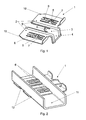
- Each exemplary embodiment 1, 1' and 1" of the self-locking bracket, shown in Fig. 1 to Fig. 7, has a form of a single-element shape, manufactured by die-stamping of the steel sheet.
- the bracket 1 shown in Fig. 1 to Fig. 3 has two mounting surfaces 2 connected by the joining surface 3, which is ended with the perpendicular mounting plate 4.
- each mounting surface 2 there is a cut-out 5 that embraces elastic locking element 6 and elastic abutting element 7. These elements have a form of two springy plates.
- each mounting surface comprises longitudinal die-stamped reinforcing bead 9 extending farther along the mounting plate 4, as well as guiding chamfers 10.
- the blocking element 8 is disposed in the joining surface 3.
- two mounting slots 12 are made in each of two upward-bent flanges of the U-shaped side support 11, wherein the slots are parallel to the surface of the side support web and have widths nearly the same as the widths of the mounting surfaces 2.
- Attaching the bracket 1 to the side support consists of sliding the bracket, from whichever side of the side support 11 into the mounting slots 12 until the working edge of locking elements 6 interlocks from inside with a wall of the side support flange 11, which occurs by virtue of resilient force of the abutting elements 7.
- the blocking element 8 performs a function of a limiter, which abutting against the side support flange from its outer side disables further insertion of the bracket 1 into the side support 11 and provides exertion of the sufficient interlocking force onto the outer side of the flange by means of appropriately shaped elastic abutting elements 7. In this way the position of the bracket is reliably secured against accidental displacement caused by e.g. vibrations of the motor vehicle radiator.
- the blocking element is disposed within some distance (a) from the working edge of the locking elements 6. That distance depends on the type of the locking elements, and in presented embodiment of the bracket it equals the thickness of the side support flange.
- the abutting elements 7 are located within the distance b from the locking elements 6, wherein the distance b is smaller than the distance a. Adjusting the distance b depends mainly on resilience and thickness of the metal sheet, of which the bracket is made.
- the locking elements are bent at an acute angle with respect to the surface of the side support web 11.
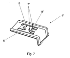
- Fig. 4 to Fig. 6 show slightly different embodiment of the bracket 1' according to the present invention.
- the elastic elements 6' are bent at acute angle towards the surface of the side support web 11 (in opposite direction than in the Fig. 3) and have a mounting orifices that facilitate dismounting of the bracket after its assembling, by means of a special tool.
- the abutting elements 7' are also of different shape.
- the blocking element is disposed within some distance a' from the working edge of the locking elements 6' whereas the abutting elements 7' are located within the distance b' from the locking elements 6', wherein the distance b' is lower than the distance a'.
- the distance a' equals to the span between the working edge of the opening 13 and the outer surface of the side support flange.
Landscapes
- Engineering & Computer Science (AREA)
- Physics & Mathematics (AREA)
- Thermal Sciences (AREA)
- Mechanical Engineering (AREA)
- General Engineering & Computer Science (AREA)
- Cooling, Air Intake And Gas Exhaust, And Fuel Tank Arrangements In Propulsion Units (AREA)
Abstract
Description
Claims (11)
- Self-locking bracket for fastening on U-shaped thin-walled profile and in particular for fastening on U- shaped side support of a motor vehicle radiator cooling core, characterised in that it has a form of a single-element shape and comprises elastic locking element (6), elastic abutting element (7) and a blocking element (8), for fixing the bracket position in mounting slots (12) parallel to the web surface of the side support (11), wherein the distance (a) between the working edge of the locking element (6) and the working edge of the blocking element (8) is greater than the distance (b) between the working edge of the locking element (6) and the working edge of the abutting element (7).
- Self-locking bracket according to claim 1, characterised in that it comprises a cut-out (5) embracing elastic locking element (6) and elastic abutting element (7).
- Self-locking bracket according to claim 2, characterised in that comprises two mounting surfaces (2) having cut-outs (5) and connected by a joining surface (3) embracing the blocking element (8).
- Self-locking bracket according to claim 2, characterised in that the blocking element (8") is made in the cut-out (5).
- Self-locking bracket according to claim 1 or 2, characterised in that the locking element (6) has a form of a pawl bent at acute angle to a web surface of the side support (11) and having a working edge for abutting from inside against the side support (11) flange.
- Self-locking bracket according to claim 1 or 2, characterised in that locking element (6') has a form of a pawl bent at acute angle to a web surface of the side support (11) and having a working edge for abutting against corresponding edges of openings (13) in the web of the side support (11).
- Self-locking bracket according to claim 1 to 6, characterised in that it comprises die-stamped reinforcing beads (9).
- Self-locking bracket according to claim 1 to 7, characterised in that it comprises guiding chamfers (10).
- Self-locking bracket according to claim 1 to 8, characterised in that it comprises at least one mounting plate (4).
- Self-locking bracket according to claim 1 to 9, characterised in that it is made of steel.
- Self-locking bracket according to claim 10, characterised in that it is made of high-resilient steel.
Applications Claiming Priority (2)
| Application Number | Priority Date | Filing Date | Title |
|---|---|---|---|
| PL35954203A PL359542A1 (en) | 2003-04-04 | 2003-04-04 | Self-latching bracket |
| PL35954203 | 2003-04-04 |
Publications (2)
| Publication Number | Publication Date |
|---|---|
| EP1464909A2 true EP1464909A2 (en) | 2004-10-06 |
| EP1464909A3 EP1464909A3 (en) | 2007-10-17 |
Family
ID=32845213
Family Applications (1)
| Application Number | Title | Priority Date | Filing Date |
|---|---|---|---|
| EP04460003A Withdrawn EP1464909A3 (en) | 2003-04-04 | 2004-03-30 | Self-locking bracket |
Country Status (2)
| Country | Link |
|---|---|
| EP (1) | EP1464909A3 (en) |
| PL (1) | PL359542A1 (en) |
Cited By (2)
| Publication number | Priority date | Publication date | Assignee | Title |
|---|---|---|---|---|
| EP1939575B1 (en) * | 2006-12-27 | 2018-07-25 | MAHLE International GmbH | Arrangement of a first component mounted onto a second component by means of a mounting bracket |
| EP3543550A1 (en) * | 2018-03-22 | 2019-09-25 | Valeo Autosystemy SP. Z.O.O. | Heat exchanger |
Family Cites Families (5)
| Publication number | Priority date | Publication date | Assignee | Title |
|---|---|---|---|---|
| US2857995A (en) * | 1955-12-21 | 1958-10-28 | Kawneer Co | Wall facing |
| US3319983A (en) * | 1960-12-27 | 1967-05-16 | Georgia Marble Co | Anchoring system for the installation of slabs on vertical and overhead surfaces |
| JPH0732867A (en) * | 1993-07-19 | 1995-02-03 | Showa Alum Corp | Heat exchanger |
| DE19930689B4 (en) * | 1999-07-02 | 2004-11-25 | Behr Gmbh & Co. Kg | Heat exchanger with holder |
| DE10065795A1 (en) * | 2000-12-22 | 2002-07-11 | Takata Europa Vehicle Safety T | holder |
-
2003
- 2003-04-04 PL PL35954203A patent/PL359542A1/en not_active Application Discontinuation
-
2004
- 2004-03-30 EP EP04460003A patent/EP1464909A3/en not_active Withdrawn
Cited By (2)
| Publication number | Priority date | Publication date | Assignee | Title |
|---|---|---|---|---|
| EP1939575B1 (en) * | 2006-12-27 | 2018-07-25 | MAHLE International GmbH | Arrangement of a first component mounted onto a second component by means of a mounting bracket |
| EP3543550A1 (en) * | 2018-03-22 | 2019-09-25 | Valeo Autosystemy SP. Z.O.O. | Heat exchanger |
Also Published As
| Publication number | Publication date |
|---|---|
| EP1464909A3 (en) | 2007-10-17 |
| PL359542A1 (en) | 2004-10-18 |
Similar Documents
| Publication | Publication Date | Title |
|---|---|---|
| JP4361941B2 (en) | Wiper blade for automotive window glass | |
| US9738261B2 (en) | Windscreen wiper device | |
| EP1849666B1 (en) | A windscreen wiper device | |
| CN100564116C (en) | Adapter for the articulation of a wiper blade to a wiper arm | |
| US7120971B2 (en) | Low insertion effort u-base retainer | |
| JP4547333B2 (en) | Device and method for releasably connecting a wiper blade to a drivable wiper arm | |
| US7634834B2 (en) | Windshield wiper assembly having a body made of spring steel | |
| US8671604B2 (en) | Marking carrier for marking a floating caliper brake | |
| US6099007A (en) | Vehicle access step assembly | |
| CN102656065A (en) | Wiper blades with flat beam construction | |
| JP2010195397A (en) | Assembly of wiper blade, and assembly of wiper | |
| KR102494626B1 (en) | Hybrid Windshield Wiper Blades | |
| JP3714739B2 (en) | Mall clip | |
| EP1939575A2 (en) | Mounting bracket | |
| US20170203648A1 (en) | An integrated bracket for automotive heat exchanger | |
| JP4337097B2 (en) | Reclining seat for automobiles with light alloy frame | |
| US20040105723A1 (en) | Attaching device for fuel tank band | |
| CN1906115B (en) | Substrates for escalators or moving walkways | |
| US20040183330A1 (en) | Assembly unit for insertion into a mounting hole and instrument panel for receiving assembly unit | |
| JP2007120862A (en) | Air conditioner | |
| US20050140131A1 (en) | Motor vehicle frame rail strengthening system | |
| US12304433B1 (en) | Windshield wiper assembly structure | |
| JP2000179931A (en) | Heat exchanger fixing device in air conditioner | |
| JP2003137012A (en) | Assistant grip mounting structure | |
| JP2003175786A (en) | Vehicle grille mounting structure |
Legal Events
| Date | Code | Title | Description |
|---|---|---|---|
| PUAI | Public reference made under article 153(3) epc to a published international application that has entered the european phase |
Free format text: ORIGINAL CODE: 0009012 |
|
| AK | Designated contracting states |
Kind code of ref document: A2 Designated state(s): AT BE BG CH CY CZ DE DK EE ES FI FR GB GR HU IE IT LI LU MC NL PL PT RO SE SI SK TR |
|
| AX | Request for extension of the european patent |
Extension state: AL LT LV MK |
|
| PUAL | Search report despatched |
Free format text: ORIGINAL CODE: 0009013 |
|
| AK | Designated contracting states |
Kind code of ref document: A3 Designated state(s): AT BE BG CH CY CZ DE DK EE ES FI FR GB GR HU IE IT LI LU MC NL PL PT RO SE SI SK TR |
|
| AX | Request for extension of the european patent |
Extension state: AL LT LV MK |
|
| 17P | Request for examination filed |
Effective date: 20080417 |
|
| AKX | Designation fees paid |
Designated state(s): AT BE BG CH CY CZ DE DK EE ES FI FR GB GR HU IE IT LI LU MC NL PL PT RO SE SI SK TR |
|
| 17Q | First examination report despatched |
Effective date: 20080611 |
|
| STAA | Information on the status of an ep patent application or granted ep patent |
Free format text: STATUS: THE APPLICATION IS DEEMED TO BE WITHDRAWN |
|
| 18D | Application deemed to be withdrawn |
Effective date: 20100722 |