EP1464903A2 - Expansion device with shutoff mechanism - Google Patents
Expansion device with shutoff mechanism Download PDFInfo
- Publication number
- EP1464903A2 EP1464903A2 EP04075963A EP04075963A EP1464903A2 EP 1464903 A2 EP1464903 A2 EP 1464903A2 EP 04075963 A EP04075963 A EP 04075963A EP 04075963 A EP04075963 A EP 04075963A EP 1464903 A2 EP1464903 A2 EP 1464903A2
- Authority
- EP
- European Patent Office
- Prior art keywords
- inlet
- extending
- outlet
- valve seat
- cage
- Prior art date
- Legal status (The legal status is an assumption and is not a legal conclusion. Google has not performed a legal analysis and makes no representation as to the accuracy of the status listed.)
- Granted
Links
Images
Classifications
-
- B—PERFORMING OPERATIONS; TRANSPORTING
- B60—VEHICLES IN GENERAL
- B60H—ARRANGEMENTS OF HEATING, COOLING, VENTILATING OR OTHER AIR-TREATING DEVICES SPECIALLY ADAPTED FOR PASSENGER OR GOODS SPACES OF VEHICLES
- B60H1/00—Heating, cooling or ventilating devices
- B60H1/00507—Details, e.g. mounting arrangements, desaeration devices
- B60H1/00585—Means for monitoring, testing or servicing the air-conditioning
-
- F—MECHANICAL ENGINEERING; LIGHTING; HEATING; WEAPONS; BLASTING
- F25—REFRIGERATION OR COOLING; COMBINED HEATING AND REFRIGERATION SYSTEMS; HEAT PUMP SYSTEMS; MANUFACTURE OR STORAGE OF ICE; LIQUEFACTION SOLIDIFICATION OF GASES
- F25B—REFRIGERATION MACHINES, PLANTS OR SYSTEMS; COMBINED HEATING AND REFRIGERATION SYSTEMS; HEAT PUMP SYSTEMS
- F25B41/00—Fluid-circulation arrangements
- F25B41/20—Disposition of valves, e.g. of on-off valves or flow control valves
- F25B41/24—Arrangement of shut-off valves for disconnecting a part of the refrigerant cycle, e.g. an outdoor part
-
- F—MECHANICAL ENGINEERING; LIGHTING; HEATING; WEAPONS; BLASTING
- F25—REFRIGERATION OR COOLING; COMBINED HEATING AND REFRIGERATION SYSTEMS; HEAT PUMP SYSTEMS; MANUFACTURE OR STORAGE OF ICE; LIQUEFACTION SOLIDIFICATION OF GASES
- F25B—REFRIGERATION MACHINES, PLANTS OR SYSTEMS; COMBINED HEATING AND REFRIGERATION SYSTEMS; HEAT PUMP SYSTEMS
- F25B45/00—Arrangements for charging or discharging refrigerant
-
- F—MECHANICAL ENGINEERING; LIGHTING; HEATING; WEAPONS; BLASTING
- F25—REFRIGERATION OR COOLING; COMBINED HEATING AND REFRIGERATION SYSTEMS; HEAT PUMP SYSTEMS; MANUFACTURE OR STORAGE OF ICE; LIQUEFACTION SOLIDIFICATION OF GASES
- F25B—REFRIGERATION MACHINES, PLANTS OR SYSTEMS; COMBINED HEATING AND REFRIGERATION SYSTEMS; HEAT PUMP SYSTEMS
- F25B2500/00—Problems to be solved
- F25B2500/18—Optimization, e.g. high integration of refrigeration components
-
- F—MECHANICAL ENGINEERING; LIGHTING; HEATING; WEAPONS; BLASTING
- F25—REFRIGERATION OR COOLING; COMBINED HEATING AND REFRIGERATION SYSTEMS; HEAT PUMP SYSTEMS; MANUFACTURE OR STORAGE OF ICE; LIQUEFACTION SOLIDIFICATION OF GASES
- F25B—REFRIGERATION MACHINES, PLANTS OR SYSTEMS; COMBINED HEATING AND REFRIGERATION SYSTEMS; HEAT PUMP SYSTEMS
- F25B2500/00—Problems to be solved
- F25B2500/27—Problems to be solved characterised by the stop of the refrigeration cycle
Definitions
- the subject invention generally relates to an expansion device for use in an air conditioning system of a motor vehicle. More specifically, the subject invention relates to an expansion device that controls the flow of refrigerant to an evaporator of the air conditioning system.
- Expansion devices e.g., thermostatic expansion valves (TXV) and orifice tubes, are known in the art.
- expansion devices have been utilized to regulate, i.e., control, flow of refrigerant in air conditioning systems for many years.
- the air conditioning systems also include a refrigerant compressor, a condenser, a receiver, and an evaporator.
- the refrigerant is in a vapor or gaseous phase as it exits the evaporator.
- Another desirable functional feature in such an air conditioning system is the ability to limit the amount of refrigerant in the evaporator while the system is not operating, the evaporator being in the passenger compartment of the vehicle. In order to accomplish this function, it would be necessary to employ a shut-off valve to control flow to the evaporator.
- the subject invention provides a unique expansion device that is able to perform the functions of refrigerant expansion, flow control, and shut-off.
- An expansion device assembly includes a valve body having an axis and an inlet end and an outlet end with an orifice tube extending through the body for conveying refrigerant from an inlet pipe to an outlet pipe while expanding the refrigerant into the outlet pipe.
- a conical shaped valve seat forms an inlet to the orifice tube and flares radially outwardly.
- a plunger has a conical shaped valve end for engaging and sealing the conical valve seat to prevent refrigerant from entering the orifice tube.
- a rod extends axially from the valve end and a solenoid coil surrounds the rod for moving the valve end out of engagement with the valve seat.
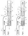
- the invention provides an orifice tube and a normally closed, solenoid activated, shut-off mechanism integrated into a single device that performs both refrigerant expansion during operation and shut-off during non-operating conditions. This is accomplished by adding a trumpet-like end to the orifice tube to serve as a valve-sealing surface when engaged by a plunger of complimentary design and dimensions that is solenoid activated. The motion of the plunger is linear and is retracted by the solenoid during system operation to allow flow of refrigerant and is moved to an open position with the aid of a spring as the solenoid circuit is deactivated. The travel of the plunger is guided to the trumpet valve seat by the cage supporting the orifice tube filter screen.
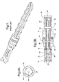
- expansion valve assembly is shown schematically in Figures 2-4.
- the expansion valve is disposed in the well-known air conditioning assembly between the condenser and evaporator to expand the fluid that has been compressed by a compressor that supplies the condenser.
- the assembly includes a valve body 12 having an axis and an inlet end 14 and an outlet end 16.
- a seal 18 is disposed about said valve body 12 for sealing engagement with an outlet pipe 20.
- the system would also include an inlet pipe 22 that is offset from the outlet pipe 20 to define an offset chamber 24 surrounding the inlet to the valve assembly.
- a cage extends from the ends 14 and 16 of the body 12 and the cage supports a screen cover.
- the cage and screen cover may be one unit or divided into inlet and outlet cages and screen covers.
- an outlet cage extends axially from the outlet end 16 of the body 12 and comprises four equally spaced stringers 26 extending to a distal end defined by a circular rib 28.
- Another rib 30 is disposed adjacent the outlet end 16 of the valve body 12.
- An outlet screen cover 32 is supported by the outlet cage to prevent the passage of debris.
- an inlet cage extends axially from the inlet end 14 of the body 12 and comprising the same or independent stringers 27 extending to a circular rib 34 disposed at a solenoid end with a plurality of circular ribs 36 and 38 spaced along the stringers 27, with one 38 of the ribs disposed adjacent the inlet end or face 14 of the valve body 12.
- An inlet screen cover 40 is supported by the inlet cage and extends from the inlet end 14 of the body 12 to the rib 34 at the solenoid end.
- the inlet and outlet cages may be connected or independent of one another with the circular ribs 30 and 38 thereof abutting the body 12.
- the inlet screen 40 has a large diameter 42 adjacent to and smaller than the diameter of the body 12 and a smaller diameter 44 extending from the large diameter 42 to the rib 34 at the solenoid end.
- An orifice tube 46 extends through the body 12 for conveying refrigerant from the inlet pipe 22 to the outlet pipe 20 while expanding the refrigerant into the outlet pipe 20.
- a conical shaped valve seat 48 forms an inlet to the orifice tube 46 and flares radially outwardly to the small diameter 44 of the inlet screen cover.
- a plunger 50 defines a conical shaped valve end 52 for engaging and sealing the conical valve seat 48 to prevent refrigerant from entering the orifice tube 46.
- An axially extending rod 54 extends from the valve end 52.
- a solenoid coil 56 is disposed at the circular rib 34 of the solenoid end of the inlet screen 40 and surrounds the rod 54 for moving the valve end 52 out of engagement with the valve seat 48, the rod 54 being magnetic to react with the solenoid 56.
- a spring 58 interacts between the plunger 50 and the solenoid 56 for urging the plunger 50 into the valve seat 48.
- the plunger 50 is guided along its path by the four stringers 27 in the inlet cage.
Landscapes
- Engineering & Computer Science (AREA)
- Physics & Mathematics (AREA)
- Mechanical Engineering (AREA)
- Thermal Sciences (AREA)
- General Engineering & Computer Science (AREA)
- Magnetically Actuated Valves (AREA)
- Seal Device For Vehicle (AREA)
- Push-Button Switches (AREA)
- Control Of Combustion (AREA)
- Preventing Unauthorised Actuation Of Valves (AREA)
Abstract
Description
Claims (10)
- An expansion valve assembly comprising;
a body (12) having an axis and an inlet end (14) and an outlet end (16), an orifice tube (46) extending through said body (12) for conveying refrigerant from an inlet pipe (22) to an outlet pipe (20) while expanding the refrigerant into the outlet pipe (20),
a conical shaped valve seat (48) forming an inlet to said orifice tube (46) and flaring radially outwardly,
a plunger (50) having a conical shaped valve end (52) for engaging and sealing said conical valve seat (48) to prevent refrigerant from entering said orifice tube (46) and an axially extending rod (54) extending from said valve end (52), and
a solenoid coil (56) surrounding said rod (54) for moving said valve end (52) out of engagement with said valve seat (48). - An assembly as set forth in claim 1 including a cage extending from said ends of said body (12) and a screen cover supported by said cage.
- An assembly as set forth in claim 2 wherein said cage includes an outlet cage extending axially from said outlet end (16) of said body (12) and comprising a plurality of stringers extending to a distal end and a plurality of circular ribs spaced along said stringers , and an outlet screen cover supported by said outlet cage.
- An assembly as set forth in claim 3 wherein said cage further includes an inlet cage extending axially from said inlet end (14) of said body (12) and comprising a plurality of stringers extending to a solenoid end and a plurality of circular ribs spaced along said stringers, and an inlet screen cover supported by said inlet cage and extending from said inlet end (14) of said body (12) to said solenoid end.
- An assembly as set forth in claim 4 wherein said inlet screen has a large diameter adjacent to and smaller than the diameter of said body (12) and a smaller diameter extending from said large diameter to said solenoid end.
- An assembly as set forth in claim 5 wherein said conical shaped valve seat (48) flares radially outwardly to said small diameter (44) of said inlet screen.
- An assembly as set forth in claim 1 including a seal (18) disposed about said valve body (12) for sealing engagement with an outlet pipe (20).
- An assembly as set forth in claim 1 including a spring (58) interacting between said plunger (50) and said solenoid (56) for urging said plunger (50) into said valve seat (48).
- An expansion device assembly comprising;
a body (12) having an axis and an inlet end (14) and an outlet end (16),
a seal (18) disposed about said valve body (12) for sealing engagement with an outlet pipe (20),
an outlet cage extending axially from said outlet end (16) of said body (12) and comprising a plurality of stringers extending to a distal end and a plurality of circular ribs spaced along said stringers,
an outlet screen cover supported by said outlet cage,
an inlet cage extending axially from said inlet end (14) of said body (12) and comprising a plurality of stringers extending to a solenoid end and a plurality of circular ribs spaced along said stringers ,
an inlet screen cover supported by said inlet cage and extending from said inlet end (14) of said body (12) to said solenoid end,
said inlet screen having a large diameter adjacent to and smaller than the diameter of said body (12) and a smaller diameter extending from said large diameter to said solenoid end,
an orifice tube (46) extending through said body (12) for conveying refrigerant from said inlet pipe to said outlet pipe (20) while expanding said refrigerant into said outlet pipe (20),
a conical shaped valve seat (48) forming an inlet to said orifice tube (46) and flaring radially outwardly to said small diameter (44) of said inlet screen,
a plunger (50) having a conical shaped valve end (52) for engaging and sealing said conical valve seat (48) to prevent refrigerant from entering said orifice tube (46) and an axially extending rod (54) extending from said valve end (52),
a solenoid coil (56) disposed at said solenoid end of said inlet screen and surrounding said rod (54) for moving said valve end (52) out of engagement with said valve seat (48), and
a spring (58) interacting between said plunger (50) and said solenoid coil (56) for urging said plunger (50) into said valve seat (48). - An air conditioning assembly comprising:a compressor;a condenser;an evaporator; andan expansion device between said condenser and said evaporator; said expansion device comprising:a body (12) having an axis and an inlet end (14) and an outlet end (16),an orifice tube (46) extending through said body (12) for conveying refrigerant from an inlet pipe to an outlet pipe (20) while expanding the refrigerant into the outlet pipe (20),a conical shaped valve seat (48) forming an inlet to said orifice tube (46) and flaring radially outwardly,a plunger (50) having a conical shaped valve end (52) for engaging and sealing said conical valve seat (48) to prevent refrigerant from entering said orifice tube (46) and an axially extending rod (54) extending from said valve end (52), anda solenoid coil (56) surrounding said rod (54) for moving said valve end (52) out of engagement with said valve seat (48).
Applications Claiming Priority (2)
| Application Number | Priority Date | Filing Date | Title |
|---|---|---|---|
| US10/405,198 US6679084B1 (en) | 2003-04-02 | 2003-04-02 | Expansion device with shutoff mechanism |
| US405198 | 2003-04-02 |
Publications (3)
| Publication Number | Publication Date |
|---|---|
| EP1464903A2 true EP1464903A2 (en) | 2004-10-06 |
| EP1464903A3 EP1464903A3 (en) | 2006-04-19 |
| EP1464903B1 EP1464903B1 (en) | 2008-01-23 |
Family
ID=30001011
Family Applications (1)
| Application Number | Title | Priority Date | Filing Date |
|---|---|---|---|
| EP04075963A Expired - Lifetime EP1464903B1 (en) | 2003-04-02 | 2004-03-29 | Expansion device with shutoff mechanism |
Country Status (4)
| Country | Link |
|---|---|
| US (1) | US6679084B1 (en) |
| EP (1) | EP1464903B1 (en) |
| AT (1) | ATE384921T1 (en) |
| DE (1) | DE602004011417T2 (en) |
Family Cites Families (7)
| Publication number | Priority date | Publication date | Assignee | Title |
|---|---|---|---|---|
| US4425767A (en) * | 1979-10-01 | 1984-01-17 | Sporlan Valve Company | Refrigeration control system for modulating electrically-operated expansion valves |
| US4632358A (en) * | 1984-07-17 | 1986-12-30 | Eaton Corporation | Automotive air conditioning system including electrically operated expansion valve |
| US5715704A (en) * | 1996-07-08 | 1998-02-10 | Ranco Incorporated Of Delaware | Refrigeration system flow control expansion valve |
| US5966960A (en) * | 1998-06-26 | 1999-10-19 | General Motors Corporation | Bi-directional refrigerant expansion valve |
| US6182457B1 (en) * | 1999-06-02 | 2001-02-06 | Ranco Incorporated Of Delaware | Electronic variable orifice tube and system for use therewith |
| US6289930B1 (en) * | 1999-07-23 | 2001-09-18 | Ward J. Simon | Refrigerant expansion device having combined piston orifice valve and solenoid-actuated closure |
| US6367283B1 (en) * | 2000-04-14 | 2002-04-09 | Ranco Incorporated | Three-stage electronically variable orifice tube |
-
2003
- 2003-04-02 US US10/405,198 patent/US6679084B1/en not_active Expired - Lifetime
-
2004
- 2004-03-29 EP EP04075963A patent/EP1464903B1/en not_active Expired - Lifetime
- 2004-03-29 AT AT04075963T patent/ATE384921T1/en not_active IP Right Cessation
- 2004-03-29 DE DE602004011417T patent/DE602004011417T2/en not_active Expired - Lifetime
Also Published As
| Publication number | Publication date |
|---|---|
| US6679084B1 (en) | 2004-01-20 |
| EP1464903A3 (en) | 2006-04-19 |
| ATE384921T1 (en) | 2008-02-15 |
| DE602004011417T2 (en) | 2009-01-15 |
| DE602004011417D1 (en) | 2008-03-13 |
| EP1464903B1 (en) | 2008-01-23 |
Similar Documents
| Publication | Publication Date | Title |
|---|---|---|
| US3815379A (en) | Unified orifice filter/muffler expansion controller | |
| EP0713063B1 (en) | Expansion Valve | |
| US5081847A (en) | Variable flow orifice tube | |
| CN109296805B (en) | Electric valve and refrigeration cycle system | |
| US4372486A (en) | Reversible expansion valve | |
| JP5974239B2 (en) | Control valve | |
| EP1043553A2 (en) | Refrigerant system components with cartridge type thermal expansion valve and method of making same | |
| US6374624B1 (en) | On/off solenoid expansion device | |
| US5979780A (en) | Thermostatic expansion valve with integral electrically operated inlet valve | |
| US5642858A (en) | Thermal expansion valve | |
| EP1275916A2 (en) | Expansion valve | |
| JP7509961B2 (en) | Motor-operated valve and refrigeration cycle system | |
| EP2136080B1 (en) | Variable displacement compressor with a discharge pressure compensated suction shutoff valve | |
| EP1712792A2 (en) | Control valve for variable capacity compressors | |
| JP2002120547A (en) | Refrigeration cycle device and valve device used therefor | |
| US6378328B1 (en) | Blow-off orifice tube | |
| US6679084B1 (en) | Expansion device with shutoff mechanism | |
| US6450413B2 (en) | Expansion valve | |
| US6367283B1 (en) | Three-stage electronically variable orifice tube | |
| JP2018193884A (en) | Control valve | |
| US3953984A (en) | Piloted throttling valve | |
| JP2003130499A (en) | Expansion valve | |
| EP1681500B1 (en) | Non-return valve | |
| JPH08210733A (en) | Expansion valve with solenoid valve | |
| US3626715A (en) | Refrigeration component |
Legal Events
| Date | Code | Title | Description |
|---|---|---|---|
| PUAI | Public reference made under article 153(3) epc to a published international application that has entered the european phase |
Free format text: ORIGINAL CODE: 0009012 |
|
| AK | Designated contracting states |
Kind code of ref document: A2 Designated state(s): AT BE BG CH CY CZ DE DK EE ES FI FR GB GR HU IE IT LI LU MC NL PL PT RO SE SI SK TR |
|
| AX | Request for extension of the european patent |
Extension state: AL LT LV MK |
|
| PUAL | Search report despatched |
Free format text: ORIGINAL CODE: 0009013 |
|
| AK | Designated contracting states |
Kind code of ref document: A3 Designated state(s): AT BE BG CH CY CZ DE DK EE ES FI FR GB GR HU IE IT LI LU MC NL PL PT RO SE SI SK TR |
|
| AX | Request for extension of the european patent |
Extension state: AL LT LV MK |
|
| 17P | Request for examination filed |
Effective date: 20061019 |
|
| AKX | Designation fees paid |
Designated state(s): AT BE BG CH CY CZ DE DK EE ES FI FR GB GR HU IE IT LI LU MC NL PL PT RO SE SI SK TR |
|
| 17Q | First examination report despatched |
Effective date: 20070219 |
|
| GRAP | Despatch of communication of intention to grant a patent |
Free format text: ORIGINAL CODE: EPIDOSNIGR1 |
|
| GRAS | Grant fee paid |
Free format text: ORIGINAL CODE: EPIDOSNIGR3 |
|
| GRAA | (expected) grant |
Free format text: ORIGINAL CODE: 0009210 |
|
| AK | Designated contracting states |
Kind code of ref document: B1 Designated state(s): AT BE BG CH CY CZ DE DK EE ES FI FR GB GR HU IE IT LI LU MC NL PL PT RO SE SI SK TR |
|
| REG | Reference to a national code |
Ref country code: GB Ref legal event code: FG4D |
|
| REG | Reference to a national code |
Ref country code: CH Ref legal event code: EP |
|
| REG | Reference to a national code |
Ref country code: IE Ref legal event code: FG4D |
|
| REF | Corresponds to: |
Ref document number: 602004011417 Country of ref document: DE Date of ref document: 20080313 Kind code of ref document: P |
|
| NLV1 | Nl: lapsed or annulled due to failure to fulfill the requirements of art. 29p and 29m of the patents act | ||
| PG25 | Lapsed in a contracting state [announced via postgrant information from national office to epo] |
Ref country code: CH Free format text: LAPSE BECAUSE OF FAILURE TO SUBMIT A TRANSLATION OF THE DESCRIPTION OR TO PAY THE FEE WITHIN THE PRESCRIBED TIME-LIMIT Effective date: 20080123 Ref country code: FI Free format text: LAPSE BECAUSE OF FAILURE TO SUBMIT A TRANSLATION OF THE DESCRIPTION OR TO PAY THE FEE WITHIN THE PRESCRIBED TIME-LIMIT Effective date: 20080123 Ref country code: LI Free format text: LAPSE BECAUSE OF FAILURE TO SUBMIT A TRANSLATION OF THE DESCRIPTION OR TO PAY THE FEE WITHIN THE PRESCRIBED TIME-LIMIT Effective date: 20080123 Ref country code: ES Free format text: LAPSE BECAUSE OF FAILURE TO SUBMIT A TRANSLATION OF THE DESCRIPTION OR TO PAY THE FEE WITHIN THE PRESCRIBED TIME-LIMIT Effective date: 20080504 |
|
| ET | Fr: translation filed | ||
| REG | Reference to a national code |
Ref country code: CH Ref legal event code: PL |
|
| PG25 | Lapsed in a contracting state [announced via postgrant information from national office to epo] |
Ref country code: BG Free format text: LAPSE BECAUSE OF FAILURE TO SUBMIT A TRANSLATION OF THE DESCRIPTION OR TO PAY THE FEE WITHIN THE PRESCRIBED TIME-LIMIT Effective date: 20080423 Ref country code: AT Free format text: LAPSE BECAUSE OF FAILURE TO SUBMIT A TRANSLATION OF THE DESCRIPTION OR TO PAY THE FEE WITHIN THE PRESCRIBED TIME-LIMIT Effective date: 20080123 |
|
| PG25 | Lapsed in a contracting state [announced via postgrant information from national office to epo] |
Ref country code: PT Free format text: LAPSE BECAUSE OF FAILURE TO SUBMIT A TRANSLATION OF THE DESCRIPTION OR TO PAY THE FEE WITHIN THE PRESCRIBED TIME-LIMIT Effective date: 20080623 Ref country code: BE Free format text: LAPSE BECAUSE OF FAILURE TO SUBMIT A TRANSLATION OF THE DESCRIPTION OR TO PAY THE FEE WITHIN THE PRESCRIBED TIME-LIMIT Effective date: 20080123 Ref country code: SI Free format text: LAPSE BECAUSE OF FAILURE TO SUBMIT A TRANSLATION OF THE DESCRIPTION OR TO PAY THE FEE WITHIN THE PRESCRIBED TIME-LIMIT Effective date: 20080123 Ref country code: PL Free format text: LAPSE BECAUSE OF FAILURE TO SUBMIT A TRANSLATION OF THE DESCRIPTION OR TO PAY THE FEE WITHIN THE PRESCRIBED TIME-LIMIT Effective date: 20080123 |
|
| PG25 | Lapsed in a contracting state [announced via postgrant information from national office to epo] |
Ref country code: SE Free format text: LAPSE BECAUSE OF FAILURE TO SUBMIT A TRANSLATION OF THE DESCRIPTION OR TO PAY THE FEE WITHIN THE PRESCRIBED TIME-LIMIT Effective date: 20080423 Ref country code: MC Free format text: LAPSE BECAUSE OF NON-PAYMENT OF DUE FEES Effective date: 20080331 Ref country code: DK Free format text: LAPSE BECAUSE OF FAILURE TO SUBMIT A TRANSLATION OF THE DESCRIPTION OR TO PAY THE FEE WITHIN THE PRESCRIBED TIME-LIMIT Effective date: 20080123 Ref country code: NL Free format text: LAPSE BECAUSE OF FAILURE TO SUBMIT A TRANSLATION OF THE DESCRIPTION OR TO PAY THE FEE WITHIN THE PRESCRIBED TIME-LIMIT Effective date: 20080123 Ref country code: CZ Free format text: LAPSE BECAUSE OF FAILURE TO SUBMIT A TRANSLATION OF THE DESCRIPTION OR TO PAY THE FEE WITHIN THE PRESCRIBED TIME-LIMIT Effective date: 20080123 Ref country code: SK Free format text: LAPSE BECAUSE OF FAILURE TO SUBMIT A TRANSLATION OF THE DESCRIPTION OR TO PAY THE FEE WITHIN THE PRESCRIBED TIME-LIMIT Effective date: 20080123 |
|
| PG25 | Lapsed in a contracting state [announced via postgrant information from national office to epo] |
Ref country code: RO Free format text: LAPSE BECAUSE OF FAILURE TO SUBMIT A TRANSLATION OF THE DESCRIPTION OR TO PAY THE FEE WITHIN THE PRESCRIBED TIME-LIMIT Effective date: 20080123 |
|
| PLBE | No opposition filed within time limit |
Free format text: ORIGINAL CODE: 0009261 |
|
| STAA | Information on the status of an ep patent application or granted ep patent |
Free format text: STATUS: NO OPPOSITION FILED WITHIN TIME LIMIT |
|
| GBPC | Gb: european patent ceased through non-payment of renewal fee |
Effective date: 20080423 |
|
| 26N | No opposition filed |
Effective date: 20081024 |
|
| PG25 | Lapsed in a contracting state [announced via postgrant information from national office to epo] |
Ref country code: EE Free format text: LAPSE BECAUSE OF FAILURE TO SUBMIT A TRANSLATION OF THE DESCRIPTION OR TO PAY THE FEE WITHIN THE PRESCRIBED TIME-LIMIT Effective date: 20080123 Ref country code: IE Free format text: LAPSE BECAUSE OF NON-PAYMENT OF DUE FEES Effective date: 20080331 |
|
| PG25 | Lapsed in a contracting state [announced via postgrant information from national office to epo] |
Ref country code: GB Free format text: LAPSE BECAUSE OF NON-PAYMENT OF DUE FEES Effective date: 20080423 |
|
| PG25 | Lapsed in a contracting state [announced via postgrant information from national office to epo] |
Ref country code: CY Free format text: LAPSE BECAUSE OF FAILURE TO SUBMIT A TRANSLATION OF THE DESCRIPTION OR TO PAY THE FEE WITHIN THE PRESCRIBED TIME-LIMIT Effective date: 20080123 |
|
| PG25 | Lapsed in a contracting state [announced via postgrant information from national office to epo] |
Ref country code: IT Free format text: LAPSE BECAUSE OF FAILURE TO SUBMIT A TRANSLATION OF THE DESCRIPTION OR TO PAY THE FEE WITHIN THE PRESCRIBED TIME-LIMIT Effective date: 20080123 |
|
| PG25 | Lapsed in a contracting state [announced via postgrant information from national office to epo] |
Ref country code: HU Free format text: LAPSE BECAUSE OF FAILURE TO SUBMIT A TRANSLATION OF THE DESCRIPTION OR TO PAY THE FEE WITHIN THE PRESCRIBED TIME-LIMIT Effective date: 20080724 Ref country code: LU Free format text: LAPSE BECAUSE OF NON-PAYMENT OF DUE FEES Effective date: 20080329 |
|
| PG25 | Lapsed in a contracting state [announced via postgrant information from national office to epo] |
Ref country code: TR Free format text: LAPSE BECAUSE OF FAILURE TO SUBMIT A TRANSLATION OF THE DESCRIPTION OR TO PAY THE FEE WITHIN THE PRESCRIBED TIME-LIMIT Effective date: 20080123 |
|
| PG25 | Lapsed in a contracting state [announced via postgrant information from national office to epo] |
Ref country code: GR Free format text: LAPSE BECAUSE OF FAILURE TO SUBMIT A TRANSLATION OF THE DESCRIPTION OR TO PAY THE FEE WITHIN THE PRESCRIBED TIME-LIMIT Effective date: 20080424 |
|
| REG | Reference to a national code |
Ref country code: DE Ref legal event code: R082 Ref document number: 602004011417 Country of ref document: DE Representative=s name: BRP RENAUD UND PARTNER MBB RECHTSANWAELTE PATE, DE Ref country code: DE Ref legal event code: R082 Ref document number: 602004011417 Country of ref document: DE Representative=s name: BRP RENAUD UND PARTNER MBB, DE Ref country code: DE Ref legal event code: R081 Ref document number: 602004011417 Country of ref document: DE Owner name: MAHLE INTERNATIONAL GMBH, DE Free format text: FORMER OWNER: DELPHI TECHNOLOGIES, INC., TROY, MICH., US |
|
| REG | Reference to a national code |
Ref country code: FR Ref legal event code: PLFP Year of fee payment: 13 |
|
| REG | Reference to a national code |
Ref country code: FR Ref legal event code: PLFP Year of fee payment: 14 |
|
| REG | Reference to a national code |
Ref country code: FR Ref legal event code: TP Owner name: MAHLE INTERNATIONAL GMBH, DE Effective date: 20180103 |
|
| REG | Reference to a national code |
Ref country code: FR Ref legal event code: PLFP Year of fee payment: 15 |
|
| PGFP | Annual fee paid to national office [announced via postgrant information from national office to epo] |
Ref country code: DE Payment date: 20190528 Year of fee payment: 16 |
|
| PGFP | Annual fee paid to national office [announced via postgrant information from national office to epo] |
Ref country code: FR Payment date: 20190903 Year of fee payment: 16 |
|
| REG | Reference to a national code |
Ref country code: DE Ref legal event code: R119 Ref document number: 602004011417 Country of ref document: DE |
|
| PG25 | Lapsed in a contracting state [announced via postgrant information from national office to epo] |
Ref country code: DE Free format text: LAPSE BECAUSE OF NON-PAYMENT OF DUE FEES Effective date: 20201001 Ref country code: FR Free format text: LAPSE BECAUSE OF NON-PAYMENT OF DUE FEES Effective date: 20200331 |